
Bedienungsanleitung
Operation Manual
Made in Europe
Viessmann
Modelltec
hnik GmbH
Bahnhofstraße 2a
D - 35116 Hatzfeld-Reddighausen
+49 6452 9340-0
www.viessmann-modell.de
92489
Stand 06/sw
10/2023
Ho/Kf
Made in Europe
Modellbauartikel, kein Spielzeug! Nicht geeignet für
Kinder unter 14 Jahren! Anleitung aufbewahren!
Model building item, not a toy! Not suitable for children
under the age of 14 years! Keep these instructions!
Ce n’est pas un jouet! Ne convient pas aux enfants de
moins de 14 ans! Conservez cette notice d’instructions!
Não é um brinquedo! Não aconselhável para menores
de 14 anos! Conservar o manual de instruções!
Modelbouwartikel, geen speelgoed! Niet geschikt voor
kinderen onder 14 jaar! Gebruiksaanwijzing bewaren!
Articolo di modellismo, non è un giocattolo! Non adat-
to a bambini al di sotto dei 14 anni! Conservare istruzioni
per l’uso!
Artículo para modelismo ¡No es un juguete! No
recomendado para menores de 14 años! Conserva las
instrucciones de servicio!
DE
EN
FR
NL
IT
ES
PT
H0, TT, N Waggon-Innenbeleuchtung
H0, TT, N Coach lighting
5090 mit 8 weißen LEDs / with 8 white LEDs
5091 mit 8 gelben LEDs / with 8 yellow LEDs
5092 mit 8 warmweißen LEDs /
with 8 warm-white LEDs
1. Wichtige Hinweise
Bitte lesen Sie vor der ersten Anwendung des Produk-
tes bzw. dessen Einbau diese Bedienungsanleitung
aufmerksam durch und bewahren Sie diese auf. Sie
ist Teil des Produktes.
1.1 Sicherheitshinweise
Vorsicht:
Stromschlaggefahr!
Alle Anschluss- und Montagearbeiten nur bei abge-
schalteter Betriebsspannung durchführen!
Ausschließlich nach VDE/EN gefertigte Modellbahn-
transformatoren verwenden!
Stromquellen unbedingt so absichern, dass es bei
einem Kurzschluss nicht zum Kabelbrand kommen
kann.
1.2 Das Produkt richtig verwenden
Dieses Produkt ist bestimmt:
- Zum Einbau in Modelleisenbahn-Waggons unter
Beachtung der für dieses Produkt geltenden
Verarbeitungshinweise.
- Zum Betrieb mit einer Betriebsspannung von
maximal 16 V AC~ oder 24 V DC=/Digitalsignal.
- Zum Betrieb in trockenen Räumen.
Jeder darüber hinausgehende Gebrauch gilt als nicht
bestimmungsgemäß. Für daraus resultierende Schä-
den haftet der Hersteller nicht.
2. Hinweise zum Einbau
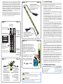
- Die Leiterplatte kann an der in Abb. 1 markierten
Stelle abgesägt und so an die Waggonlänge ange-
passt werden.
- Das kurze Stück kann nicht weiter verwendet wer-
den. Achten Sie beim Sägen darauf, die silbernen
Anschlusspunkte sowie Bauteile und Leiterbahnen
der Leiterplatte nicht zu beschädigen.
1. Important information
Please read this manual completely and attentively
before using the product for the first time. Keep this
manual. It is part of the product.
1.1 Safety instructions
Caution:
Electrical hazard!
Make sure that the power supply is switched
off when you mount the device and connect the
cables!
The power sources must be protected to avoid the
risk of burning cables.
1.2 Using the product for its correct
purpose
This product is intended:
- For mounting into a model train car. You must obey
the following instructions.
- For operation with a power supply up to 16 V
AC~ or 24 V DC=/Digital signal.
- For operating in a dry area.
Using the product for any other purpose is not ap-
proved and is considered inappropriate. The manu-
facturer is not responsible for any damage resulting
from the improper use of this product.
2. Mounting Instructions
- The printed circuit board (PCB) can be adapted
to the size of the car by sawing it through at the
spot shown in fig. 1. The small 32 mm strip is not
intended for further use. Be careful not to damage
the silver connection pads, the components and the
conductor paths on the PCB when sawing.
- Solder connecting wires to the connection points
shown in fig. 1. All left and right connection pads
are interconnected. Therefore, it is sufficient to
connect only one wire to each side. One side has
to be connected to the left wheel pick-up (resp.
the car ground for Märklin), the other side has to
be connected to the right wheel pick-up of the car
(resp. the current pick-up wiper for Märklin). See fig. 2.
Observe the soldering instructions. (paragraph 4.)
- Mount the PCB underneath the roof of the car with
double-sided adhesive tape. The tape must not be
attached to the part marked in fig. 1, as this may get
hot in operation.
3. Soldering Instructions
If you are not practiced at soldering, please first read
these soldering instructions before picking up the
soldering iron. Soldering is something that has to be
learned.
1. Never use soldering paste or fluid when soldering
electronic connections. These contain an acid that
destroys cables, components and conductor paths.
2. As soldering material, use only electronics solder
with a rosin core, which also acts as a fluxing agent.
3. Use a small soldering iron with max. 30 watt power
and a thin soldering tip (< 1 mm). The soldering tip
must be free of scaling so that the heat can be con-
ducted away well. This means that the heat from
the soldering iron must be conducted well to the
point to be soldered.
4. The soldering itself should be done quickly because
soldering for too long can destroy components. It
also leads to loosening of the soldering pads and
conductor paths from PCBs.
5. At first strip the insulation from the ends of the
cable, and twist the stripped ends between your
finger tips. Then presolder the wires. To solder, the
well-tinned soldering tip is placed at the soldering
point so that both components which you want to
connect are contacted. At the same time (not too
much) solder has to be added and heated. As
soon as the solder begins to flow, remove it from
the soldering point. Then wait a moment until the
remaining solder has run well, and then remove the
soldering iron from the soldering point.
6. Ensure that the cable just soldered is not moved
for approx. 5 seconds after you have removed the
soldering iron. Then only a shiny silver, perfect sol-
dering point remains.
7. A clean, unoxidized soldering tip is required for a
perfect soldering point. It is absolutely impossible
to solder cleanly using a dirty soldering tip. You
should therefore always remove excess solder and
dirt from the iron with a moist sponge or a silicon
wiper after making a soldering point.
8. Uninsulated ends of the wire which stand out are
cut off directly above the soldering point with a wire
cutter. We recommend a full-flush wire cutter (like
the hobby-cutter, item 7815 from Viessmann).
9. When welding electronic components, be sure not
to solder for more than 5 seconds, because other-
wise the components will be destroyed.
DE
EN
4. Technical data
Supply voltage: 6 – 16 V AC~
6 – 24 V DC=/Digital signal
Constant brightness: from 6 V DC= / AC~
Current consumption: 30 mA maximal
Dimensions: ca. W 9 x L 132 mm
Entsorgen Sie dieses Produkt nicht über den (unsortierten)
Hausmüll, sondern führen Sie es der Wiederverwertung zu.
Do not dispose of this product through (unsorted) domestic
waste, supply it to recycling instead.
Subject to change without prior notice. No liability for mistakes and printing
errors.
You will find the latest version of the manual on the Viessmann website using
the item number.
Änderungen vorbehalten. Keine Haftung für Druckfehler und Irrtümer.
Die aktuelle Version der Anleitung finden Sie auf der Viessmann Homepage
unter der Artikelnummer.
Points de collecte sur www.quefairedemesdechets.fr
À DÉPOSER
EN MAGASIN À DÉPOSER
EN DÉCHÈTERIE
OU
Cet modéle
se recycle
FR
FR

- Kabel an den in Abb. 1 markierten Anschluss-
punkten anlöten. Alle linken und alle rechten An-
schlusspunkte sind auf der Leiterplatte miteinander
verbunden. Daher ist es ausreichend, je Seite nur
ein Kabel anzuschließen. Eine Seite wird mit dem
linken Radschleifer (bzw. der Waggon-Masse bei
Märklin), die andere Seite mit dem rechten Rad-
schleifer des Waggons (bzw. dem Mittelschleifer
bei Märklin) verbunden (Abb. 2). Beachten Sie die
Lötanleitung unter Punkt 3.
- Die Platine wird mit doppelseitigem Klebeband unter
dem Waggondach fixiert. Das Klebeband muss an
dem in Abb. 1 markierten Bereich ausgespart wer-
den, da dieser warm werden kann.
~ 100 mm ~ 32 mm*
Anschlusspunkte
connection points
Variante
variant
Anschlusspunkte
connection points
Anschlusspunkte
connection points
Original
original
Stelle zum
Durchsägen
der Platine
spot for
sawing
through the
circuit board
Stelle zum
Durchsägen
der Platine
spot for
sawing
through the
circuit board
Bereich, der im
Betrieb warm
werden kann
area possibliy
getting hot during
operation
Achtung!
Leiterplatte
nicht biegen!
Attention!
Don't bend the
circuit board!
Fig. 1
Abb. 1
zum linken
Radschleifer
oder bei
Märklin zur
Waggon-Masse
to the left
wheel pick-up
or for Märklin
to the
car ground
zum rechten
Radschleifer
oder bei
Märklin zum
Mittelschleifer
to the right
wheel pick-up
or for Märklin
to the current
pick-up wiper
Fig. 2
Abb. 2
stromführende
Kupplung Art. 5048
electrical coupler
item 5048
stromführende
Kupplung Art. 5048
electrical coupler
item 5048
Fig. 3
Abb. 3
Anschluss für einen zu-
sätzlichen Stützelko zur
Überbrückung längerer
stromloser Abschnitte. Je
höher die Kapazität (in µF),
desto länger die überbrück-
te Zeit.
Connection for an ad-
ditional buffer capa-
citor to bridge longer
currentless sections.
20 V
µF time
Fig. 4
Abb. 4
3. Lötanleitung
Wenn Sie im Löten noch nicht geübt sind, lesen Sie bit-
te zuerst diese Lötanleitung, bevor Sie zum Lötkolben
greifen. Denn Löten will gelernt sein:
1.
Verwenden Sie beim Löten von elektronischen
Schaltungen grundsätzlich nie Lötwasser oder Löt-
fett. Diese enthalten eine Säure, die Bauteile und
Leiterbahnen zerstört.
2.
Als Lötmaterial darf nur Elektronikzinn mit einer
Kolophoniumseele verwendet werden, die zugleich
als Flussmittel dient.
3.
Verwenden Sie einen kleinen Lötkolben mit maximal
30 Watt Heizleistung und einer dünnen Lötspitze (<
1 mm). Die Lötspitze muss zunderfrei sein, damit
die Wärme gut abgeleitet werden kann (die Wärme
vom Lötkolben muss gut an die zu lötende Stelle
geleitet werden).
4. Die Lötung selbst soll zügig vorgenommen werden,
denn durch zu langes Löten werden Bauteile zer-
stört. Ebenso kann es zum Ablösen der Lötaugen
und Leiterbahnen von der Leiterplatte führen.
5.
Kabel werden zunächst am Ende abisoliert, verdrillt
und dann verzinnt. Zum Löten wird dann die gut
verzinnte Lötspitze so auf die Lötstelle gehalten,
dass zugleich beide zu verbindende Komponen-
ten berührt werden. Gleichzeitig wird (nicht zuviel)
Lötzinn zugeführt und mit aufgeheizt. Sobald das
Lötzinn zu fließen beginnt, nehmen Sie es von der
Lötstelle fort. Jetzt warten Sie noch einen Augen-
blick, bis das zurückgebliebene Lot gut verlaufen ist
und nehmen dann den Lötkolben von der Lötstelle
ab.
6.
Achten Sie darauf, dass das soeben angelötete
Kabel, nachdem Sie den Lötkolben abgenommen
haben, ca. 5 Sekunden lang nicht bewegt wird. Zu-
rück bleibt dann eine silbrig glänzende, einwandfreie
Lötstelle.
7.
Voraussetzung für eine einwandfreie Lötstelle und
gutes Löten ist eine saubere, nicht oxidierte Löt-
spitze. Denn mit einer schmutzigen Lötspitze ist es
absolut unmöglich, sauber zu löten. Nehmen Sie
daher nach jedem Löten überflüssiges Lötzinn und
Schmutz mit einem feuchten Schwamm oder einem
Silikonabstreifer vom Kolben ab.
8.
Nach dem Löten werden überstehende blanke En-
den der Kabel direkt über der Lötstelle mit einem
Seitenschneider ab-geschnitten, vorzugsweise mit
einem Seitenschneider ohne Wate (Schräge) - z. B.
dem Bastel-Schneider, Viessmann Art. 7815.
9.
Beim Löten an elektronischen Bauteilen ist beson-
ders darauf zu achten, dass eine Lötzeit von ca.
5 Sekunden nicht überschritten wird, da sonst die
Bauteile oder die Kupferbahnen zerstört werden
4. Technische Daten
Versorgungsspannung: 6 – 16 V AC~
6 – 24 V DC=/Digitalsignal
Konstante Helligkeit: ab 6 V DC= / AC~
Stromaufnahme: 30 mA maximal
Abmessungen: ca. B 9 x L 132 mm
Achtung!
Die Nennspannung des Kondensators muss
mindestens 20 V betragen! Polung beachten!
Attention!
The rated voltage of the capacitor has to be 20 V
minimum. Take care of the polarity!
-
 1
1
-
 2
2


Viessmann 5090 Bedienungsanleitung
- Typ
- Bedienungsanleitung
in anderen Sprachen
- English: Viessmann 5090 Owner's manual
- italiano: Viessmann 5090 Manuale del proprietario
Verwandte Artikel
Andere Dokumente
-
Parkside PLPD 60 A1 Translation Of The Original Instructions
-
-
Wentronic 51091 Spezifikation
-
Parkside PLLL 16 A2 Original Instructions Manual
-
Parkside PLS 48 C1 Original Instruction
-
-
-
Conrad Relay card equipped 1 pc(s) 5 V DC REL-PCB4 1 1 change-over 5 V DC Bedienungsanleitung
-
VARDAFLEX 86478 Bedienungsanleitung