WAGO EPSITRON COMPACT Power 787-1212 Operating And Assembly Instructions
- Typ
- Operating And Assembly Instructions

9970-0966
s07870000_00000005 V1.0.0 © 2016
WAGO Kontakttechnik GmbH & Co. KG
Hansastr. 27
D-32423 Minden
www.wago.com
D
Gebrauchs- und Montageanleitung
Bitte aufbewahren!
Technische Änderungen vorbehalten
Support: Telefon: +49 (0) 571/8 87 - 5 55 / Fax: +49 (0) 571/8 87 - 85 55
E-Mail: [email protected]
EPSITRON
®
COMPACT Power
PE
L
N
DC+
DC+
DC -
DC -
Gleichstromversorgung
787-1202 / 787-1212 /
787-1216 / 787-1226
1 Sicherheitshinweise
1.1 Allgemeine Sicherheitshinweise
GEFAHR
Nicht an Geräten unter Spannung arbeiten!
Gefährliche elektrische Spannung kann zu elektrischem Schlag und Verbrennungen
führen.
Schalten Sie immer alle verwendeten Spannungsversorgungen für das Gerät ab, bevor
Sie das Gerät montieren, installieren, Störungen beheben oder Wartungsarbeiten
vornehmen.
GEFAHR
Berührbare spannungsführende Teile!
Die Sicherstellung eines notwendigen Berührungsschutzes liegt in der Verantwor-
tung des Anlagenerrichters. Die für den jeweiligen Anwendungsfall zu beachtenden
Errichtungs bestimmungen sind einzuhalten.
i
Hinweis
Nur gültig in Zusammenhang mit dem Gerätehandbuch!
Dieser Beipackzettel ist nur gültig in Zusammenhang mit dem Gerätehandbuch!
Dieses Handbuch nden Sie im Internet unter www.wago.com.
Beachten Sie außerdem die Angaben auf dem Gerätegehäuse!
Befolgen Sie besonders die folgenden Punkte:
• Das beschriebene Gerät darf ausschließlich durch qualizierte Elektrofachkräfte gemäß
DIN EN 50110-1/-2 sowie IEC 60364 installiert werden.
• Prüfen Sie vor Inbetriebnahme das Gerät auf eventuelle Transportschäden. Bei mechanischen
Beschädigungen darf das Gerät nicht in Betrieb genommen werden.
• Schützen Sie das Gerät vor unzulässiger Beanspruchung. Insbesondere beim Transport und
bei der Handhabung dürfen keine Bauelemente verbogen und/oder Isolationsabstände
verändert werden.
• Installieren Sie das Gerät nur in abgeschlossenen elektrischen Betriebsstätten gemäß
DIN EN 50178.
• Montieren Sie das Gerät nur in trockenen Innenräumen.
• Die Montage des Gerätes darf nicht auf oder an leicht entzündlichen Materialien erfolgen.
• Halten Sie den geforderten Mindestabstand zu benachbarten Teilen unbedingt ein, um die
Kühlung nicht zu behindern!
• Beim Einsatz gemäß EN 60335 muss der Betreiber eine entsprechende Vorrichtung in der
Gerätezuleitung zur Abschaltung der Netzspannung vorsehen.
1.2 Besondere Hinweise beim Einsatz als Installationseinbaugerät
GEFAHR
Berührungsschutz beim Einsatz als Installationseinbaugerät einhalten!
Beim Einsatz als Installationseinbaugerät gemäß DIN 43880 (Hausinstallation) hat der
Elektro installateur für einen entsprechenden Berührungsschutz zu sorgen.
Verwenden Sie das Gerät 787-1202 bzw. 787-1212 beim Einsatz als Installationsein-
baugerät nur mit aufgesetzter Frontplatte!
2 Technische Daten
Tabelle 1: Gerät
787-1202 787-1212 787-1216 787-1226
Abmessungen (mm) B × H × T
Tiefe inklusive Befestigungsclips (mm)
54 × 56 × 90
120
72 × 56 × 90
120
108 × 56 × 90
120
144 × 56 × 90
120
Gewicht 210 g 270 g 415 g 510 g
Tabelle 2: Verdrahtung
Querschnitt 0,2 mm² … 2,5 mm² / AWG 24 … 12
Abisolierlänge 9 mm … 10 mm / 0,35 in … 0,39 in
ACHTUNG
Leiterquerschnitte entsprechend der Strombelastung wählen!
Der Ausgangsstrom eines Netzteiles kann im Fehlerfall bis zu 2 × I
OUT
betragen.
Verwenden Sie nur Leiterquerschnitte, die der Strombelastung genügen!
Tabelle 3: Montage
Einbaulage
(weitere Einbaulagen auf Anfrage)
Abstände
Oben Unten Vorn Hinten Links Rechts
Vertikale Montage (Frontplatte vorn) 70 mm 70 mm 70 mm --- 0 mm 0 mm
Horizontale Montage (Frontplatte oben) 70 mm --- 70 mm 70 mm 20 mm 20 mm
Horizontale Montage (Frontplatte unten) --- 70 mm 70 mm 70 mm 20 mm 20 mm
3 Ansicht
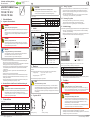
Tabelle 4: Ansicht (Beispiel: 787-1226)
g
h
j
i
f
e
d
c
b
a
Pos. Belegung
a Befestigungsclips für Schraubmontage
(im Lieferumfang enthalten)
b
Eingang picoMAX
®
5 (N L PE)
c
Ausgang picoMAX
®
5 (+ + - -)
d Potentiometer zum Einstellen der
Ausgangsspannung im Bereich
DC 22 V … 26 V
e LED-Anzeige
LED grün: Ausgangsspannung liegt an
f Frontplatte
787-1202 / 787-1212: abnehmbar
787-1216 / 787-1226: nicht abnehmbar
g Typenschild
h Belüftungsschlitze
i Lasche zur Montage/Demontage auf einer
Tragschiene
j Schiebeschalter zum Einstellen des Ein-
gangsspannungsbereiches (nur 787-1226):
110 V AC 100 V … 120 V
230 V AC 200 V … 240 V
4 Montieren
Montieren Sie das Gerät zwecks ordnungsgemäßer Entwärmung vertikal (Belüftungsschlitze oben
und unten).
Bei der Montage mit Frontplatte oben oder unten sind folgende Werte nicht zu überschreiten:
• Ausgangsleistung: 50 % (787-1202 / 787-1212 / 787-1216)
40 % (787-1226)
• Umgebungstemperatur: 55 °C
Abweichende Einbaulagen erfolgen auf eigene Gefahr.
ESD
Elektrostatische Entladung vermeiden!
In den Geräten sind elektronische Komponenten integriert, die Sie durch elektrosta-
tische Entladung bei Berührung zerstören können. Beachten Sie die Sicherheitsmaß-
nahmen gegen elektrostatische Entladung gemäß DIN EN 61340-5-1/-3. Achten Sie
beim Umgang mit den Geräten auf gute Erdung der Umgebung (Personen, Arbeitsplatz
und Verpackung).
4.1 Tragschiene DIN 35
1.
2.
2.
1.
Abbildung 1: Montage Abbildung 2: Demontage
4.1.1 Montage Tragschiene
Montieren Sie das Gerät gemäß EN 60715 durch Aufrasten auf die Tragschiene (siehe Abbildung 1):
1. Setzen Sie das Gerät mit der Tragschienenführung an die Oberkante der Tragschiene ein.
2. Drücken Sie das Gerät in Richtung Tragschiene [1] und rasten Sie das Gerät bei gleichzei-
tigem Zug an der Lasche (i) auf [2].
3. Zur sicheren Fixierung auf der Tragschiene setzen Sie vor und nach dem Gerät (bei block-
weiser Anordnung: vor und nach den Geräten) je eine Endklammer.
4.1.2 Demontage Tragschiene
1. Zur Demontage (siehe Abbildung 2) ziehen Sie die Lasche (i) nach unten [1].
Benutzen Sie dafür einen Schraubendreher oder ein Betätigungswerkzeug.
2. Kippen Sie das Gerät nach vorn [2] und hängen Sie es aus der Tragschiene aus.
4.2 Schraubbefestigung
Lage und Abmessungen der Befestigungsclips entnehmen Sie der dem Gerät beiliegenden Bohrschablone.
1. Führen Sie je einen Befestigungsclip in die entsprechende obere und untere Einrastöffnung
am Gehäuse ein (siehe Abbildung 3).
2. Drücken Sie den Befestigungsclip so weit herunter, bis er mit einem hörbaren Klick einrastet.
3. Überprüfen Sie den festen Sitz durch leichtes Rütteln am Befestigungsclip.
1.1
1.2
2.1
2.2
1.1
2.1
Abbildung 3: Einrastöffnungen für Befestigungsclips – Ansicht von oben/Ansicht von unten
Tabelle 5: Legende zur Abbildung „Einrastöffnungen für Befestigungsclips“
Pos. Beschreibung
1.1 Einrastöffnung oben; rückseitige Befestigung (787-1226: 2 ×)
1.2 Einrastöffnung oben; seitliche Befestigung (nur 787-1202 / 787-1212)
2.1 Einrastöffnung unten; rückseitige Befestigung (787-1226: 2 ×)
2.2 Einrastöffnung unten; seitliche Befestigung (nur 787-1202 / 787-1212)
4.
Befestigen Sie das Gerät mit entsprechenden Schrauben M4 (nicht im Lieferumfang enthalten).
Beachten Sie dabei das maximale Drehmoment von 2,9 Nm.
5 Verdrahten
GEFAHR
Korrekten Steckplatz der picoMAX
®
-Federleisten beachten!
Beim falschen Stecken der Eingangsfederleiste (b) in den Anschluss für den Ausgang (c)
kann es zu einer gefährlichen Spannungsabgabe von 230 V auf der Ausgangsseite kommen.
Achten Sie beim Stecken auf den korrekten Steckplatz der jeweiligen Federleiste!
WARNUNG
Werkzeug nicht in die Belüftungsschlitze stecken!
Gelangt die Klinge des benutzten Werkzeugs durch die Belüftungsschlitze, können
Komponenten im Inneren des Gerätes beschädigt werden. Dadurch kann es zu schwer-
wiegenden Folgeschäden mit Verletzungsgefahr durch Fehlfunktionen, zu hohe
Wärmeentwicklung oder elektrischen Strom führen!
Beachten Sie beim Einsatz eines Schraubendrehers oder eines Betätigungswerkzeuges
die korrekte Positionierung zwischen Rastlasche und Federleiste!
Folgende Leiter können direkt, ohne Verwendung eines Werkzeugs gesteckt werden:
• feindrähtige Leiter mit Aderendhülse mit Kunststoffkragen; alle Querschnitte
• feindrähtige Leiter mit Aderendhülse ohne Kunststoffkragen; Querschnitt > 0,5 mm²/AWG 22
• eindrähtige Leiter; Querschnitt > 0,25 mm²/AWG 24

9970-0966
s07870000_00000005 V1.0.0 © 2016
WAGO Kontakttechnik GmbH & Co. KG
Hansastr. 27
D-32423 Minden
www.wago.com
En
Operating and Assembly instructions
Please keep!
Subject to design changes
Support: Phone: +49 (0) 571/8 87 - 5 55 / Fax: +49 (0) 571/8 87 - 85 55
Mail: [email protected]
EPSITRON
®
COMPACT Power
PE
L
N
DC+
DC+
DC -
DC -
DC power supply
787-1202 / 787-1212 /
787-1216 / 787-1226
1 Safety Information
1.1 General
Do not work when devices are energized!
High voltage can cause electric shock or burns.
Switch off all power to the device prior to performing any installation, repair or main-
tenance work.
Live parts are likely to be touched!
The party setting up the device is responsible for providing appropriate touch guards.
The installation regulations must be observed for each individual application.
i
Only valid in conjunction with the device‘s manual!
These instructions are only applicable in conjunction with the device‘s manual!
This manual is available on the Internet at www.wago.com.
In addition, please observe the information provided on the device’s housing.
Please especially observe the following:
• The device described in these instructions shall only be installed by a qualied electrician
according to both DIN EN 50110-1/-2 and IEC 60364.
• Before startup, check the device for any damage that may have occurred during shipping. The
device shall not be put into operation in the event of mechanical damage.
• Ensure proper handling to protect device during shipping and handling. Parts must not be bent
and electrical spacing must remain constant.
• Only install this device in closed electrical service locations in accordance with
DIN EN 50178.
• Only install this device in dry indoor rooms.
• Do not install the devices on or in the vicinity of easily ammable materials.
• Keep sufcient distance from adjacent components to avoid interfering with the cooling!
• When used in accordance with EN 60335, the operator must provide a suitable mains isolator
in the device supply line
Improper use and failure to follow these instructions for use will render the warranty or guarantee null
and void.
1.2 Special Notes on Use as a DIN-Rail Built-in Installation Device
Ensure contact protection when used as a DIN-rail built-in installation device!
When used as a DIN-rail built-in installation device according to DIN 43880 (domestic
installation), the electrical installer must provide appropriate contact protection.
Only use the device 787-1202 or 787-1212 as a DIN-rail built-in installation device
with the front panel tted.
2 Technical Data
Table 1: Device
787-1202 787-1212 787-1216 787-1226
Dimensions (mm) W × H × D
Depth including fastening clips (mm)
54 × 56 × 90
120
72 × 56 × 90
120
108 × 56 × 90
120
144 × 56 × 90
120
Weight 210 g 270 g 415 g 510 g
Table 2: Wiring
Cross section 0.2 mm² … 2.5 mm² / AWG 24 … 12
Strip length 9 mm … 10 mm / 0.35 in … 0.39 in
Select conductor cross sections as required for current load!
In the event of a fault, the output current of a power supply can be up to 2 × I
OUT
.
Only use conductor cross sections designed for this current load.
Table 3: Mounting
Mounting position
(Other mounting positions on request)
Distances
Top Bottom Front Rear Left Right
Vertical mounting (front panel front) 70 mm 70 mm 70 mm --- 0 mm 0 mm
Horizontal mounting (front panel top) 70 mm --- 70 mm 70 mm 20 mm 20 mm
Horizontal mounting (front panel bottom) --- 70 mm 70 mm 70 mm 20 mm 20 mm
3 View
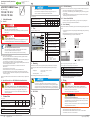
Table 4: View (Example: 787-1226)
g
h
j
i
f
e
d
c
b
a
Pos. Assignment
a Fastening clips for screw mounting
(included)
b
picoMAX
®
5 input (N L PE)
c
picoMAX
®
5 output (+ + - -)
d Potentiometer for setting the output
voltage between 22 VDC … 26 VDC
e LED indicator
LED green: Output voltage present
f Front panel
787-1202 / 787-1212: removable
787-1216 / 787-1226: not removable
g Type plate
h Ventilation slots
i Mount/removal latch on a DIN-rail
j Slide switch for setting the input voltage
range (only 787-1226):
110 V 100 VAC … 120 VAC
230 V 200 VAC … 240 VAC
4 Mounting
Install the device vertically to ensure proper heat dissipation (ventilation slots above and below).
The following values should not be exceeded when installing with the front panel at the top or
bottom:
• Output power: 50 % (787-1202 / 787-1212 / 787-1216)
40 % (787-1226)
• Ambient temperature: 55 °C
Other mounting positions should only be used at one‘s own risk!
Avoid electrostatic discharge!
The devices are equipped with electronic components that you may destroy by
electrostatic discharge when you touch. Please observe the safety precautions against
electrostatic discharge in accordance with DIN EN 61340-5-1/-3. Pay attention while
handling the devices to good grounding of the environment (persons, job and packing).
4.1 DIN 35 Rail
1.
2.
2.
1.
Figure 1: Mounting Figure 2: Removal
4.1.1 DIN-Rail Mounting
Install the device in accordance to EN 60715 by snapping it onto DIN-rail without tools (see gure 1):
1. Place the device with its DIN-rail guide on the top edge of the DIN-rail.
2. Press the device onto the DIN-rail [1] while simultaneously pulling on the latch (i) [2] until it
locks into place.
3. To ensure secure fastening on the DIN-rail, t end clips on either side of the device (with a
block arrangement: on either side of the devices).
4.1.2 Removal from DIN-Rail
1. To remove (see gure 2) pull down the latch (i) [1] using a screwdriver or operating tool.
2. Tilt the device forward [2] and unhook it from the DIN rail.
4.2 Screw Mounting
The position and dimensions for the fastening clips are listed in the drilling template supplied with the
device.
1. Fit one fastening clip into each corresponding top and bottom snap-t opening on the housing
(see gure 3).
2. Push down the fastening clip until it locks into place with an audible click.
3. Gently shake the fastening clip to verify that it is tted securely.
1.1
1.2
2.1
2.2
1.1
2.1
Figure 3: Snap-t openings for fastening clips – top/bottom view
Table 5: Legend for the “Snap-t openings for fastening clips” gure
Pos. Description
1.1 Snap-t opening top; rear fastening (787-1226: 2 ×)
1.2 Snap-t opening top; side fastening (only 787-1202 / 787-1212)
2.1 Snap-t opening bottom; rear fastening (787-1226: 2 ×)
2.2 Snap-t opening bottom; side fastening (only 787-1202 / 787-1212)
4. Fasten the device with the appropriate M4 screws (not included).
Observe the maximum torque of 2.9 Nm.
5 Wiring
Make sure that the picoMAX
®
Female Connectors are mated properly!
Mismating the input female connector (b) into the output connector (c) may lead to a
hazardous voltage of 230 V on the output side.
Make sure that the female connector is properly mated!
Do not insert a tool into the ventilation slots!
Components inside the device may be damaged if the blade of an operating tool enters
the ventilation slots. This may lead to serious damage with a risk of injury caused by
malfunction, overheating or electric shock!
When using a screwdriver or an actuation tool, ensure correct positioning between the
locking latch and the female connector!
The following conductors can be inserted directly without tools:
• ne-stranded conductors with insulated ferrule, all cross sections
• ne-stranded conductors with uninsulated ferrule, cross section > 0.5 mm²/AWG 22
• solid conductors, cross section > 0.25 mm²/AWG 24
-
 1
1
-
 2
2


WAGO EPSITRON COMPACT Power 787-1212 Operating And Assembly Instructions
- Typ
- Operating And Assembly Instructions
in anderen Sprachen
- English: WAGO EPSITRON COMPACT Power 787-1212
Verwandte Artikel
-
WAGO COMPACT POWER Benutzerhandbuch
-
-
-
-
-
-
-
-
-