
D
Bedienungsanleitung Steckkarte ZM-SKS B
D
Steckkarte ZM-SKS B / Rev. 1.3 – 1

2 – Steckkarte ZM-SKS B / Rev. 1.3
1. Inhaltsangabe 3. Allgemeine Sicherheitshinweise
2. Symbolerklärung
Gewährleistung
Eine Gewährleistung in Bezug auf Funktion und Sicherheit
erfolgt nur, wenn die Warn- und Sicherheitshinweise in dieser
Betriebsanleitung beachtet werden.
Für Personen- oder Sachschäden, die durch Nichtbeachtung
der Warn- und Sicherheitshinweise eintreten, haftet die
Marantec GmbH + Co.KG nicht.
Bestimmungsgemäße Verwendung
Die ZM-SKS B ist eine Erweiterung für die Steuerung
AS 210 B. Sie ist ausschließlich für die Steuerung von
Toranlagen bestimmt.
Der Betrieb ist nur in trockenen Räumen zulässig.
Zielgruppe
Nur qualizierte und geschulte Elektrofachkräfte dürfen die
Steckkarte anschließen, programmieren und warten.
Qualizierte und geschulte Elektrofachkräfte erfüllen folgende
Anforderungen:
- Kenntnis der allgemeinen und speziellen Sicherheits- und
Unfallverhütungsvorschriften,
- Kenntnis der einschlägigen elektrotechnischen Vorschriften,
- Ausbildung in Gebrauch und Pege angemessener Sicher-
heitsausrüstung,
- Fähigkeit, Gefahren in Zusammenhang mit Elektrizität zu
erkennen.
Hinweise zu Montage und Anschluss
- Vor elektrischen Arbeiten muss die Anlage von der Strom-
versorgung getrennt werden. Während der Arbeiten muss
sichergestellt werden, dass die Stromversorgung unterbro-
chen bleibt.
- Die örtlichen Schutzbestimmungen sind zu beachten.
- Netz- und Steuerleitungen müssen getrennt verlegt werden.
Gefahr vor Personenschäden!
Die Sicherheitshinweise sind unbedingt zu
beachten!
Warnung vor Sachschäden!
Die Sicherheitshinweise sind unbedingt zu
beachten!
Information
Besondere Hinweise
ODER
Verweis auf andere Informationsquellen
1. Inhaltsangabe 2
2. Symbolerklärung 2
3. Allgemeine Sicherheitshinweise 2
4. Produktübersicht 3
5. Inbetriebnahme 4
6. EU-Konformitätserklärung 7

D
Steckkarte ZM-SKS B / Rev. 1.3 – 3
Prüfgrundlagen und Vorschriften
Bei Anschluss, Programmierung und Wartung müssen
folgende Vorschriften beachtet werden (ohne Anspruch auf
Vollständigkeit).
Bauproduktnormen
- EN 13241-1 (Produkte ohne Feuer und Rauchschutzeigen-
schaften)
- EN 12445 (Nutzungssicherheit kraftbetätigter Tore -
Prüfverfahren)
- EN 12453 (Nutzungssicherheit kraftbetätigter Tore -
Anforderungen)
- EN 12978 (Schutzeinrichtungen für kraftbetätigte Tore
- Anforderungen und Prüfverfahren)
EMV
- EN 55014-1 (Störaussendung Haushaltsgeräte)
- EN 61000-3-2 (Rückwirkungen in Strom versorgungsnetzen –
Oberschwingungen)
- EN 61000-3-3 (Rückwirkungen in Strom versorgungsnetzen –
Spannungsschwankungen)
- EN 61000-6-2 (Elektromagnetische Verträglichkeit (EMV) -
Teil 6-2: Fachgrundnormen – Störfestigkeit - Industriebereich)
- EN 61000-6-3 (Elektromagnetische Verträglichkeit (EMV) -
Teil 6-3: Fachgrundnormen – Störaus sendung - Wohnbereich,
Geschäfts- und Gewerbebereiche sowie Kleinbetriebe)
Maschinenrichtlinie
- EN 60204-1 (Sicherheit von Maschinen, elektrische Ausrüs-
tung von Maschinen; Teil 1: Allgemeine Anforderungen)
- EN 12100-1 (Sicherheit von Maschinen - Grundbegriffe,
allgemeine Gestaltungsleitsätze; Teil 1: Grundsätzliche
Terminologie, Methodologie)
Niederspannung
- EN 60335-1 (Sicherheit elektrischer Geräte für den Haus-
gebrauch und ähnliche Zwecke)
- EN 60335-2-103 (Besondere Anforderungen für Antriebe für
Tore, Türen und Fenster)
Berufsgenossenschaft D
- BGR 232 (Richtlinien für kraftbetätigte Fenster, Türen und
Tore)
4.1 Funktionen
Die Steckkarte ZM SKS B bietet folgende Funktionen, die über
Dippschalter eingestellt werden:
- Auswertung OPTO- elektronische SKS
- Auswertung 8,2 kOhm SKS
- Testung für pneumatische SKS
- Automatische Zufahrt
- Hoicht oder Rotampel Funktion
- Laufzeitüberwachung 120 sek
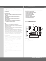
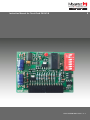
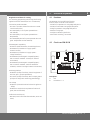
4.2 Steckkarte ZM SKS B
Erklärung:
A: LED
B: Dippschalter 1 - 7
4. Produktübersicht
A
B

4 – Steckkarte ZM-SKS B / Rev. 1.3
5. Inbetriebnahme
5.1 Allgemeines
Warnung!
Um eine einwandfreie Funktion zu
gewährleisten müssen die folgenden Punkte
zutreffen:
- Das Tor ist montiert und funktions fähig.
- Der Getriebemotor ist montiert und funkti-
onsbereit.
- Die Befehls- und Sicherheitsgeräte sind
montiert und funktionsbereit.
- Die Steuerung AS 210 B ist ordnungsgemäß
montiert und verkabelt.
- Alle Motoranschlüsse sind steuerungs- und
motorseitig festgezogen.
- Alle an der Steuerung anzuschließenden
Komponenten benötigen mindestens eine
zusätzliche Isolierung mit einer Bemessungs-
spannung von > 230 V.
Information:
Für die Montage der Torsteuerung
AS 210 B ist die entsprechende Anleitung zu
berücksichtigen.
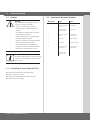
5.2 Einbau in Platine AS 210 B
* Anlage spannungsfrei schalten.
* Jumper 1, 2 und 5 entfernen.
* Platine ZM-SKS B B in Steckleiste X7 stecken.
* Spannung einschalten.
5.3 Übersicht Dippschalterfunktionen
Dippschalter ON OFF
1 8,2 kOhm SKS OPTO SKS
2 DW Testung
aktiviert
Keine Testung
3 Automatischer
Zulauf
Kein Automa-
tischer Zulauf
4 Hoicht Rotampel
5 Verzögerung Ohne Verzögerung
6 Dauersignal
(Ampel)
Blinksignal
(Ampel)
7 Lernen
Offenhaltezeit
-

D
Steckkarte ZM-SKS B / Rev. 1.3 – 5
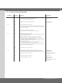
5.4 Übersicht Dippschalterfunktionen
Dippschalter Stellung Funktion Anschluss
Dipp 1 ON - Auswertung für 8,2 KOhm Schließkantensystem
- Auswertung für pneumatische Schließkantensysteme,
in Verbindung mit einem 8,2 KOhm Widerstand
Klemmleiste X3,
Klemme 7 + 8
OFF Auswertung für OPTO Schließkantensystem. Klemmleiste X3,
Klemme 7 + 8 + 9
Dipp 2 ON - DW Testung ist eingeschaltet.
- Die Testung des DW-Schalters erfolgt in der Endlage ZU.
Dabei muss der DW-Kontakt beim Aufsetzen des Tores kurz unterbrochen
werden.
-
OFF - DW Testung ist nicht eingeschaltet.
- Es erfolgt keine Testung des DW-Schalters in der Endlage ZU.
-
Dipp 3 ON - Automatischer Zulauf ist eingeschaltet.
- Aus der Torendlage AUF erfolgt eine automatische Zufahrt nach Ablauf der
eingestellten Offenhaltezeit.
Grundsätzliche Funktionen bei eingeschaltetem automatischem
Zulauf
- Nach Unterbrechung der Durchfahrtlichtschranke in der Abfahrt, erfolgt ein
Stopp und eine Wiederauffahrt, die Offenhaltezeit wird neu gestartet.
- Nach Unterbrechung der Durchfahtlichtschranke während der Offenhaltezeit,
wird die Offenhaltezeit neu gestartet.
- Nach Betätigung der SKS während der Abfahrt, erfolgt ein Stopp und eine
Wiederauffahrt, die Offenzeit wird neu gestartet.
Wird die SKS 3mal während eines Zyklus betätigt erfolgt keine autom. Abfahrt
mehr.
-
OFF - Automatischer Zulauf ist ausgeschaltet. -
Dipp 4 ON - Hoichtfunktion wird durch den AUF-Befehl eingeschaltet.
- Bei der Einstellung auf Hoicht hat das Licht eine Nachleucht dauer von 2 Min.
Es kann über den Dippschalter 5 auf Verzögerung gestellt werden, dass heißt,
der Antrieb läuft erst an, nachdem das Licht 3 Sek. an ist.
Potentialfreier Schaltkontakt K3,
Klemmreihe X9,
Klemme 1 + 2 zum schalten
einer ext. Lichtquelle.
OFF - Rotampel Funktion ist eingeschaltet.
- Über den Dipp 5 kann zwischen 2 Varianten gewählt werden.
Potentialfreier Schaltkontakt K3,
Klemmreihe X9,
Klemme 1 + 2 zum schalten
einer Rotampel.
Dipp 5 ON Rotampel mit Verzögerung
(bezogen auf die Funktionen von Dipp 4, OFF)
- Vorwarnung bei autom. Zulaufen 3 Sek. Leuchten oder Blinken (Dipp 6).
- Vorwarnung bei jeder Fahrt, 3 Sek. Leuchten oder Blinken (Dipp 6).
- Leuchten oder Blinken während der Fahrt (Dipp 6).
- 5 Sek. Nachleuchtdauer bei geschlossenem Tor
(Leuchten oder Blinken / Dipp 6).
-
OFF Rotampel ohne Verzögerung
(bezogen auf die Funktionen von Dipp 4, OFF)
- Vorwarnung bei autom. Zulauf 3 Sek. Leuchten oder Blinken
(Dipp 6).
- Leuchten oder Blinken während der Fahrt (Dipp 6).
-

6 – Steckkarte ZM-SKS B / Rev. 1.3
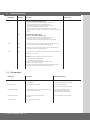
5. Inbetriebnahme
Dippschalter Stellung Funktion Anschluss
Dipp 6 ON - Dauersignal – Bei Rotampelfunktion leuchtet die Ampel dauerhaft bei Torlauf
und bei Vorwarnung.
-
OFF - Blinksignal – Bei Rotampelfunktion, blinkt die Ampel bei Torlauf und bei
Vorwarnung.
-
Dipp 7 ON Einlernen der Offenhaltezeit. Die Offenhaltezeit beinhaltet immer eine Vorwarn-
zeit von 3 Sek.
Beispiel: Es soll eine Offenhaltezeit von 20 Sek. erfolgen.
1. Tor in die Position AUF fahren.
2. Netzspannung ausschalten.
3. Automatische Zufahrt mit Dippschalter 3 einschalten.
4. Netzspannung einschalten.
5. Dippschalter 7 einschalten (LED blinkt), nach 20 Sek. wieder ausschalten.
6. Offenhaltezeit ist auf 20 Sek. programmiert.
-
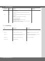
5.5 LED-Meldungen
LED Bedeutung Behebung
LED blinkt 1x SKS betätigt / gestört SKS überprüfen, ggf. Hindernis aus Torweg entfernen
LED blinkt 2x Durchfahrt-Lichtschranke ist unterbrochen Lichtschranke überprüfen, ggf. Hindernis aus Torweg
entfernen
LED blinkt 3x Testung der DW ist negativ, Tor kann in Richtung Zu nur
noch in Totmann-Funktion bewegt werden
Tor in Totmann-Funktion schließen. Nach einer positiven
DW-Testung ist die Störung beseitigt
LED blinkt 4x Laufzeit von 120 Sekunden ist überschritten Erneuter AUF- oder ZU-Befehl
LED blinkt schnell Offenhaltezeit läuft ab

D
Steckkarte ZM-SKS B / Rev. 1.3 – 7
Hersteller:
Marantec GmbH & Co. Kg, Remser Brook 11,
D-33428 Marienfeld
Hiermit erklären wir, dass die nachfolgend bezeichneten
Produkte:
Steckkarte ZM-SKS B
aufgrund ihrer Konzipierung und Bauart sowie in der von
uns in Verkehr gebrachten Ausführung, den einschlägigen
grundlegenden Sicherheits- und Gesundheitsanforderungen
der nachfolgenden EG-Richtlinien und Normen entspricht:
EG - Bauprodukten-Richtlinie 89/106/EG
DIN EN 13241-1
DIN EN 12453
DIN EN 12445
DIN EN 12978
EG - Elektromagnetische Verträglichkeit Richtlinie
2004/108/EG
EN 55014-1
EN 61000-3-2
EN 61000-3-3
EN 61000-6-2
EN 61000-6-3
EG - Maschine-Richtlinie 2006/42/EG
EN 60204-1
EN ISO 12100-1
EG - Niederspannung Richtlinie 2006/95/EG
EN 60335-1
EN 60335-2-103
BGR 232 - Richtlinie für kraftbetätigte Fenster, Türen
und Tore
Marienfeld, den 29.12.2009
Herstellerunterschrift:
Klaus Goldstein
Funktion des Unterzeichners:
Geschäftsleitung
6. EU-Konformitätserklärung

Art.-Nr. #97350

GB
Instruction Manual for Circuit Card ZM-SKS B
Circuit Card ZM-SKS B / Rev. 1.3 – 1

2 – Circuit Card ZM-SKS B / Rev. 1.3
1. Contents 3. General safety instructions
2. Key to symbols
Guarantee
The function and safety of the equipment is only
guaranteed if the warning and safety instructions included in
these operating instructions are adhered to.
Marantec GmbH + Co.KG is not liable for any personal injury
or damage to property that occurs as a result of the warning
and safety instructions being disregarded.
Using the equipment for its intended purpose
The ZM-SKS B is an add-on module for the AS 210 B controls.
It is intended exclusively for controlling door systems.
Its use is only permitted in dry rooms.
Target group
Only qualied and trained electricians may connect,
programme and service the circuit card.
Qualied and trained electricians full the following
requirements:
- they have knowledge of the general and specic safety and
accident prevention regulations,
- they have knowledge of the relevant electrical regulations
- they are trained in the use and care of appropriate safety
equipment,
- they are capable of recognising the dangers associated with
electricity.
Instructions for installation and connection
- The controls must be disconnected from the electricity supply
before carrying out electrical works. It must be ensured that
the electricity supply remains disconnected during the works.
- Local protective regulations must be complied with.
- Mains cables and control cables must be laid separately.
Danger of personal injury!
The safety instructions must be observed!
Warning! Danger to property!
The safety instructions must be observed!
Information
Special information
OR
Reference to other sources of
information
1. Contents 2
2. Key to symbols 2
3. General safety instructions 2
4. Overview of product 3
5. Initial operation 4
6. EU Declaration of Conformity 7

GB
Circuit Card ZM-SKS B / Rev. 1.3 – 3
Regulations and bases for testing
For connecting, programming and servicing, the following
regulations must be observed (the list is not exhaustive).
Construction product standards
- EN 13241-1 (Products without re resistance or smoke
control characteristics)
- EN 12445 (Safety in use of power operated doors -
Test methods)
- EN 12453 (Safety in use of power operated doors -
Requirements)
- EN 12978 (Safety devices for power operated doors and
gates - Requirements and test methods)
Electromagnetic compatibility
- EN 55014-1 (Radio disturbance, household appliances)
- EN 61000-3-2 (Disturbances in supply systems -
harmonic currents)
- EN 61000-3-3 (Disturbances in supply systems -
voltage uctuations)
- EN 61000-6-2 (Electromagnetic compatibility (EMC) -
Part 6-2: Generic standards - Immunity for industrial
environments)
- EN 61000-6-3 (Electromagnetic compatibility (EMC) -
Part 6-3: Generic standards - Emission standard for
residential, commercial and light- industrial environments)
Machinery guidelines
- EN 60204-1 (Safety of machinery, electrical equipment of
machines, part 1: general requirements)
- EN 12100-1 (Safety of machinery. Basic concepts, general
principles for design. Basic terminology, methodology)
Low voltage
- EN 60335-1 (Household and similar electrical appliances
- Safety)
- EN 60335-2-103 (Particular requirements for drives for
gates, doors and windows)
Professional association (D)
- BGR 232 (Directive for Power-driven Windows, Doors and
Gates)
4.1 Functions
The ZM SKS B circuit card offers the following
functions, which can be set via DIP switches:
- Evaluation for optoelectronic closing edge safety device
- Evaluation for 8.2 kOhm closing edge safety device
- Testing for pneumatic closing edge safety device
- Automatic closing timer
- Yard light or red trafc light function
- Excess travel monitoring, 120 seconds
4.2 Circuit card ZM SKS B
Description:
A: LED
B: DIP switches 1 – 7
4. Overview of product
A
B

4 – Circuit Card ZM-SKS B / Rev. 1.3
5. Initial operation
5.1 General
Warning!
To guarantee that the equipment functions
properly, it must be ensured that:
- the door is installed and operational.
- the drive motor is installed and ready for
operation.
- the command and safety devices are instal-
led and ready for operation.
- the AS 210 B controls are properly installed
and with all cables connected.
- all motor connections are securely tightened
both at the motor and the controls.
- each component to be connected to the
controls has at least one additional isolation
device with a rated voltage of > 230 V.
Information:
The relevant manufacturer’s instructions must be
adhered to for the installation of the AS 210 B
door controls.
5.2 Connecting to circuit board AS 210 B
* Disconnect the system from the power supply.
* Remove jumpers 1, 2 and 5.
* Plug circuit card ZM-SKS B into terminal block X7.
* Switch on the power supply.
5.3 Overview of DIP switch functions
DIP switch ON OFF
1 8,2 kOhm
closing edge safety
device
OPTO closing edge
safety device
2 Pressure switch
testing activated
No testing
3 Automatic closing
timer
No automatic
closing timer
4 Yard light Red trafc light
5 Time delay Without time delay
6 Continuous signal
(trafc light)
Flashing trafc
(light signal)
7 Learning - door
open duration
-

GB
Circuit Card ZM-SKS B / Rev. 1.3 – 5
5.4 Overview of DIP switch functions
DIP switch Setting Function Connection
DIP 1 ON - Evaluation for 8.2 KOhm closing edge safety device
- Evaluation for pneumatic closing edge safety devices,
in connection with an 8.2 KOhm resistance
Terminal block X3,
Terminals 7 + 8
OFF Evaluation for OPTO closing edge safety device. Terminal block X3,
Terminals 7 + 8 + 9
DIP 2 ON - Pressure switch testing is switched on.
- Pressure switch testing is carried out with the door at the CLOSED end positi-
on. For this, the pressure switch contact must be broken for a moment as the
door touches the ground.
-
OFF - Pressure switch testing is not switched on.
- The pressure switch is not tested at the CLOSED end position.
-
DIP 3 ON - Automatic closing timer is switched on.
- From the OPEN end position, the door closes automatically after the program-
med door-open duration expires.
Basic functions when automatic closing timer is switched on
- If the photocell barrier is interrupted during closing, the door stops and then
opens again. The door open duration starts anew.
- If the photocell barrier is interrupted during the door open duration, the door
open duration starts anew.
- If the closing edge safety system is activated during closing, the door stops
and then opens again. The door open duration starts anew.
If the closing edge safety device is activated three times during one cycle, the
door does not close automatically again.
-
OFF - Automatic closing timer is switched off. -
DIP 4 ON - Yard light function is switched on when the OPEN command is given.
- With the yard light setting, the light then stays on for 2 minutes. Via DIP
switch 5 it can be set to delay, which means that the drive does not start until
the light has been on for 3 seconds.
Potential-free
switching contact K3,
terminal block X9,
terminals 1 + 2 for connecting
an external light source.
OFF - Red trafc light function is switched on.
- 2 options are available using DIP 5.
Potential-free
switching contact K3,
terminal block X9,
terminals 1 + 2 for connecting a
red trafc light.

6 – Circuit Card ZM-SKS B / Rev. 1.3
5. Initial operation
DIP switch Setting Function Connection
DIP 5 ON Red trafc light with delay
(relates to the functions of DIP 4, OFF)
- Light shines continuously or ashes (DIP 6) to give advance
warning of automatic closing 3 seconds beforehand.
- Light shines continuously or ashes (DIP 6) to give advance
warning 3 seconds before every door movement.
- Light shines continuously or ashes during door movement (DIP 6).
- Signal (continuous or ashing / DIP 6) continues for 5 seconds after door has
closed.
-
OFF Red trafc light without delay
(relates to the functions of DIP 4, OFF)
- Light shines continuously or ashes (DIP 6) to give advance
warning of automatic closing 3 seconds beforehand.
- Light shines continuously or ashes during door movement (DIP 6).
-
DIP 6 ON - Continuous signal – for the red trafc light function the light remains on
continuously during door movements and warning periods.
-
OFF - Flashing signal – for the red trafc light function, the trafc light ashes
during door movements and warning periods.
-
DIP 7 ON „Learning“ the door open duration. The door open duration always includes a
warning time of 3 seconds.
Example: The door is required to stay open for 20 seconds:
1. Drive the door to the OPEN position.
2. Switch off the mains power supply.
3. Switch on the automatic closing timer using DIP switch 3.
4. Switch on the mains power supply.
5. Switch on DIP switch 7 (LED ashes); switch off again after 20 seconds.
6. The open door duration is now programmed to 20 seconds.
-
5.5 LED messages
LED signal Meaning Remedial measures
LED ashes once Closing edge safety device activated /
malfunctioning
Check the closing edge safety device,
remove any obstacles from path of door
LED ashes twice Photocell barrier is interrupted Check the photocell barrier,
remove any obstacles from path of door
LED ashes three times Pressure switch testing is negative, now the door can be
closed in deadman mode only
Close the door in deadman mode.
After a positive pressure switch test,
the malfunction has been remedied
LED ashes four times A running time of 120 seconds has been
exceeded
Give a new OPEN or CLOSE command
LED ashes quickly Door open duration is expiring

GB
Circuit Card ZM-SKS B / Rev. 1.3 – 7
Manufacturer:
Marantec GmbH & Co. KG, Remser Brook 11,
D-33428 Marienfeld, Germany
We hereby declare that, by virtue of their conceptual deve-
lopment and design, as well as their manufacture as we have
brought them onto the market, the products cited below:
Circuit Card ZM-SKS B
conform to the relevant basic health and safety
regulations of the following EU guidelines and standards:
EU Construction Products Directive 89/106/EU
DIN EN 13241-1
DIN EN 12453
DIN EN 12445
DIN EN 12978
EU Electromagnetic Compatibility Directive
2004/108/EU
EN 55014-1
EN 61000-3-2
EN 61000-3-3
EN 61000-6-2
EN 61000-6-3
EU Machinery Directive 2006/42/EU
EN 60204-1
EN ISO 12100-1
EU Low Voltage Directive 2006/95/EU
EN 60335-1
EN 60335-2-103
BGR 232 - Directive for Power-driven Windows, Doors
and Gates
Marienfeld, 29. December 2009
Manufacturer’s signature:
Klaus Goldstein
Position of signatory:
Manager
6. EU Declaration of Conformity

Art.-Nr. #97350
-
 1
1
-
 2
2
-
 3
3
-
 4
4
-
 5
5
-
 6
6
-
 7
7
-
 8
8
-
 9
9
-
 10
10
-
 11
11
-
 12
12
-
 13
13
-
 14
14
-
 15
15
-
 16
16


Marantec AS 210B Bedienungsanleitung
- Typ
- Bedienungsanleitung
- Dieses Handbuch eignet sich auch für
in anderen Sprachen
- English: Marantec AS 210B Owner's manual
Verwandte Artikel
-
Marantec AS 210B Erweiterung Bedienungsanleitung
-
-
Marantec CS 310 Bedienungsanleitung
-
-
Marantec CS 310 FU Bedienungsanleitung
-
-
-
-
