
D
Betriebsanleitung Torsteuerung AS 210 B
Torsteuerung AS 210 B / Rev.A 1.2 – 1

2 – Torsteuerung AS 210 B / Rev.A 1.2
1. Inhaltsangabe 3. Allgemeine Sicherheitshinweise
2. Symbolerklärung
Originalbetriebsanleitung
− Urheberrechtlich geschützt.
− Nachdruck, auch auszugsweise, nur mit unserer
Genehmigung.
− Änderungen, die dem technischen Fortschritt dienen,
vorbehalten.
− Alle Maßangaben in Millimeter.
− Darstellungen sind nicht maßstabsgetreu.
Gewährleistung
Eine Gewährleistung in Bezug auf Funktion und Sicherheit
erfolgt nur, wenn die Warn- und Sicherheitshinweise in dieser
Betriebsanleitung beachtet werden.
Für Personen- oder Sachschäden, die durch Nichtbeachtung
der Warn- und Sicherheitshinweise eintreten, haftet die
Marantec GmbH + Co.KG nicht.
Bestimmungsgemäße Verwendung
Die Steuerung AS 210 B ist ausschließlich für die Steuerung
von Toranlagen bestimmt.
Der Betrieb ist nur in trockenen Räumen zulässig.
Zielgruppe
Nur qualizierte und geschulte Elektrofachkräfte dürfen die
Steuerung anschließen, programmieren und warten.
Qualizierte und geschulte Elektrofachkräfte erfüllen folgende
Anforderungen:
− Kenntnis der allgemeinen und speziellen Sicherheits- und
Unfallverhütungsvorschriften,
− Kenntnis der einschlägigen elektrotechnischen Vorschriften,
− Ausbildung in Gebrauch und Pege angemessener Sicher-
heitsausrüstung,
− Fähigkeit, Gefahren in Zusammenhang mit Elektrizität zu
erkennen.
Hinweise zu Montage und Anschluss
− Vor elektrischen Arbeiten muss die Anlage von der Strom-
versorgung getrennt werden. Während der Arbeiten muss
sichergestellt werden, dass die Stromversorgung unterbro-
chen bleibt.
− Die örtlichen Schutzbestimmungen sind zu beachten.
− Netz- und Steuerleitungen müssen getrennt verlegt werden.
Gefahr vor Personenschäden!
Die Sicherheitshinweise sind unbedingt zu
beachten!
Warnung vor Sachschäden!
Die Sicherheitshinweise sind unbedingt zu
beachten!
Information
Besondere Hinweise
ODER
Verweis auf andere Informationsquellen
1. Inhaltsangabe 2
2. Symbolerklärung 2
3. Allgemeine Sicherheitshinweise 2
4. Produktübersicht 3
5. Inbetriebnahme 5
6. Technische Daten 10
7. EG-Einbauerklärung 11

D
Torsteuerung AS 210 B / Rev.A 1.2 – 3
Prüfgrundlagen und Vorschriften
Bei Anschluss, Programmierung und Wartung müssen
folgende Vorschriften beachtet werden (ohne Anspruch auf
Vollständigkeit).
Bauproduktnormen
− EN 13241-1 (Produkte ohne Feuer und Rauchschutzeigen-
schaften)
− EN 12445 (Nutzungssicherheit kraftbetätigter Tore -
Prüfverfahren)
− EN 12453 (Nutzungssicherheit kraftbetätigter Tore -
Anforderungen)
− EN 12978 (Schutzeinrichtungen für kraftbetätigte Tore -
Anforderungen und Prüfverfahren)
EMV
− EN 55014-1 (Störaussendung Haushaltsgeräte)
− EN 61000-3-2 (Rückwirkungen in Strom versorgungsnetzen
– Oberschwingungen)
− EN 61000-3-3 (Rückwirkungen in Strom versorgungsnetzen
– Spannungsschwankungen)
− EN 61000-6-2 (Elektromagnetische Verträglichkeit (EMV) -
Teil 6-2: Fachgrundnormen – Störfestigkeit - Industrie-
bereich)
− EN 61000-6-3 (Elektromagnetische Verträglichkeit (EMV) -
Teil 6-3: Fachgrundnormen – Störaus sendung - Wohn-
bereich, Geschäfts- und Gewerbebereiche sowie Klein-
betriebe)
Maschinenrichtlinie
− EN 60204-1 (Sicherheit von Maschinen, elektrische Ausrü-
stung von Maschinen; Teil 1: Allgemeine Anforderungen)
− EN 12100-1 (Sicherheit von Maschinen - Grundbegriffe,
allgemeine Gestaltungsleitsätze; Teil 1: Grundsätzliche
Terminologie, Methodologie)
Niederspannung
− EN 60335-1 (Sicherheit elektrischer Geräte für den Haus-
gebrauch und ähnliche Zwecke)
− EN 60335-2-103 (Besondere Anforderungen für Antriebe
für Tore, Türen und Fenster)
Ausschuss für Arbeitsstätten (ASTA)
− ASR A1.7 (Technische Regeln für Arbeitsstätten „Türen und
Tore“)
4.1 Funktionen
Die Torsteuerung AS 210 B ist in der Grundversion nur für den
Totmann-Betrieb ausgelegt.
Die Torsteuerung AS 210 B ist durch das Steck modul ZM SKS B
erweiterbar. Mit Hilfe des Steck moduls kann eine SKS-Leiste
angeschlossen werden.
Folgende Funktionen sind dann einstellbar:
− Rot-Ampel
− Hoicht
− Automatische Abfahrt
− Laufzeitüberwachung
4. Produktübersicht

4 – Torsteuerung AS 210 B / Rev.A 1.2
4. Produktübersicht
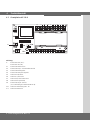
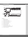
4.2 Grundplatine AS 210 B
Erklärung:
A: Einstelltaster AUF (S01) /
Einstelltaster ZU (S02)
X1: Klemmleiste Netzanschluss
X2: Klemmleiste Motor / Sicherheitskette Antrieb
X3: Klemmleiste Befehlsgeräte
X4: Klemmleiste Netzspannungswahl
X5: Steckleiste Endschalter
X6: Steckleiste 3-fach Taster
X7: Stecksockel für Platine ZM SKS B
X8: Stecksockel für Spiralkabel
X9: Klemmleiste Ampel / Hoicht
(nur in Verbindung mit Steckkarte ZM SKS B)
X10: Steckleiste Selbsthaltung AUF - ZU
X11: Steckleiste Bremsrelais
12345678910 11 12 13 14 15
123456
1 23
PE
L1 L2 L3 UVW45
X5
X3
X1 X2
X7
12
X9
AUF ZU
X4
X8
X6
J2 J1
X10
X11
J4
J5
J3
A

D
Torsteuerung AS 210 B / Rev.A 1.2 – 5
5. Inbetriebnahme
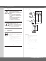
5.1 Allgemeines
Warnung!
Um eine einwandfreie Funktion zu
gewährleisten müssen die folgenden Punkte
zutreffen:
- Das Tor ist montiert und funktions fähig.
- Der Getriebemotor ist montiert und funkti-
onsbereit.
- Die Befehls- und Sicherheitsgeräte sind
montiert und funktionsbereit.
- Die Steuerung AS 210 B ist montiert.
Information:
Für die Montage des Tores, des
Getriebemotors und der Befehls- und Sicher-
heitsgeräte sind die Anleitungen der jewei-
ligen Hersteller zu berücksichtigen.
5.2 Netzanschluss
Gefahr!
Um die Funktion der Steuerung zu
gewährleisten, müssen die folgenden Punkte
zutreffen:
- Die Netzspannung muss der Angabe auf
dem Typenschild entsprechen.
- Bei Drehstrom muss ein rechts drehendes
Drehfeld vorliegen.
- Bei Festanschluss muss ein allpoliger Haupt-
schalter verwendet werden.
- Bei Drehstromanschluss dürfen nur 3er
Block sicherungsautomaten (10A) verwendet
werden.
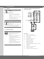
Detailschaltplan Netzanschluss und Motor
400 V / 3-phasig
Erklärung:
F1 Thermosicherung Steuerspannung
F2 Thermoschutz Motor
K1 Schütz AUF
K2 Schütz ZU
M Motor (400 V / 50 Hz / 3-Phasen)
S3 Sicherheitsendschalter AUF (Öffner)
S4 Sicherheitsendschalter ZU (Öffner)
S7 Sicherheitsschalter Nothandbedienung
(Öffner)
T1 Transformator
X1 Klemmleiste Netzanschluss
X2 Klemmleiste Motor
X4 Klemmleiste Netzspannungswahl
5
4WVU
L3 L2 L1 PE
12 3
400V
400 V / 50 Hz

6 – Torsteuerung AS 210 B / Rev.A 1.2
Detailschaltplan Netzanschluss und Motor
230 V / 3-phasig
Erklärung:
F1 Thermosicherung Steuerspannung
F2 Thermoschutz Motor
K1 Schütz AUF
K2 Schütz ZU
M Motor (230 V / 50 Hz / 3-Phasen)
S3 Sicherheitsendschalter AUF (Öffner)
S4 Sicherheitsendschalter ZU (Öffner)
S7 Sicherheitsschalter Nothandbedienung
(Öffner)
T1 Transformator
X1 Klemmleiste Netzanschluss
X2 Klemmleiste Motor
X4 Klemmleiste Netzspannungswahl
Detailschaltplan Netzanschluss und Motor
230 V / 1-phasig
Erklärung:
F1 Thermosicherung Steuerspannung
F2 Thermoschutz Motor
K1 Schütz AUF
K2 Schütz ZU
M Motor (230 V / 50 Hz)
S3 Sicherheitsendschalter AUF (Öffner)
S4 Sicherheitsendschalter ZU (Öffner)
S7 Sicherheitsschalter Nothandbedienung
(Öffner)
T1 Transformator
X1 Klemmleiste Netzanschluss
X2 Klemmleiste Motor
X4 Klemmleiste Netzspannungswahl
Anschluss:
* Steuerung an das Stromnetz anschließen.
* Steuerung an den Motor anschließen.
* Kabelgruppen sind unmittelbar vor der jeweiligen Klemme
mit einem Kabelbinder zu sichern.
5. Inbetriebnahme
5
4WVU
L3 L2 L1 PE
12 3
230V
230 V / 50 Hz
5
4NAUF ZU
LN PE
12 3
230V
230 V / 50 Hz

D
Torsteuerung AS 210 B / Rev.A 1.2 – 7
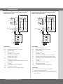
5.4 Anschlussbelegung Befehls- und
Sicherheitsgeräte
Über die Klemmen X3 und X9 können vorhandene Befehls-
und Sicherheitsgeräte angeschlossen werden.
Klemmleiste X3
- Taster STOP
- Taster AUF
- Taster ZU
- Schließkantensicherung
(SKS)
9
24 V DC max. 150 mA
- Impulseingang / Funk
9
- Durchfahrts-Lichtschranke
9
Klemmleiste X9
- Potentialfreier Anschluss für Rot-
Ampel oder Hoicht
9
9
Nur in Verbindung mit ZM SKS B Steckkarte
1
2
3
4
5
6
7
8
9
10
11
12
13
14
15
1
2
5
6
7
8
U
V
W
4
5
6
5
4
3
2
1
4
1
2
5.3 Anschlussbelegung Endschalter
(Klemme X5 und X2)
Klemmleiste X5
Klemmleiste X2
1
Endschalter AUF
2
Endschalter ZU
4
Vorendschalter ZU
(Nach Ansprechen erfolgt kein reversieren des Tores)
5
Thermoschutz Motor
6
Notbedienung (Öffner)
7
Sicherheitsendschalter ZU
8
Sicherheitsendschalter AUF

8 – Torsteuerung AS 210 B / Rev.A 1.2
5. Inbetriebnahme
8,2
8,2
1
2
3
4
5
6
7
8
9
10
11
12
13
14
15
+12 V
Sig
GND
br
gr
wt
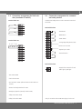
5.5 Anschlussbeispiele Befehls- und
Sicherheitsgeräte (Klemme X3)
Taster AUF / STOP / ZU
(4-Ader Lösung)
- Taster STOP
- Taster AUF
- Taster ZU
Schlüsselschalter AUF / ZU
- Taste AUF
- Taste ZU
1
2
3
4
5
6
7
8
9
10
11
12
13
14
15
5.6 Anschlussbeispiele in Verbindung mit der
Steckkarte ZM-SKS B (Klemme X3)
Für opto-elektrische Schließkantensicherung
- Der Dippschalter 1 muss auf OFF stehen.
Für 8,2 kOhm Schließkantensicherung
- Der Dippschalter 1 muss auf ON stehen.
Für pneumatische Schließkantensicherung
- Ein 8,2 kOhm Widerstand muss zum DW-Schalter in Reihe
geschaltet werden.
- Der Dippschalter 1 muss auf ON stehen.
- Der Dippschalter 2 muss auf ON stehen.
wt: weiß
gr: grün
br: braun

D
Torsteuerung AS 210 B / Rev.A 1.2 – 9
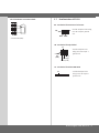
Für Lichtschranke in 3-Draht-Technik
3
Lichtschranke (NPN)
3
1
2
3
4
5
6
7
8
9
10
GND
+24V
5.7 Detailansichten AS 210 B
X6 - Stecksockel für Externen 3-fach Taster
- wird der Steckplatz nicht belegt,
muss der Jumper 4 gesteckt
sein.
X8 - Stecksockel für Spiralkabel
- wird der Steckplatz nicht
belegt, muss der Jumper 3
gesteckt sein.
X7 - Stecksockel für Platine ZM SKS B
- wird der Steckplatz nicht
belegt, muss der Jumper 5
gesteckt sein.
ZU
AUF STOP
J4
schwarz/
gelb
(STOP)
weiß (-)
J3
grün (Sig)
braun (+12V)
J5

10 – Torsteuerung AS 210 B / Rev.A 1.2
5. Inbetriebnahme
Abmessungen
Platine:
167 x 85 x 190 mm
Versorgung über L1,
L2, L3, PE:
230 V oder 400 V, 50 / 60 Hz; Aufnahmeleistung
max. 2200 W - 3,2 A; Einschaltdauer 60% bei
einer Laufzeit von max. 120 s
Absicherung: 10A K-Charakteristik
Eigenverbrauch der
Steuerung:
max. 100 mA
Steuerspannung:
24 V DC, max. 250 mA; abgesichert durch
selbstrückstellende Sicherung für externe
Sensorik; alle Steuerspannungseingänge sind
galvanisch gegenüber der Versorgung getrennt
Steuereingänge: 24V
DC, alle Eingänge sind potentialfrei anzu-
schließen. min. Signaldauer für Eingangssteuer-
befehl >100ms
Steuerausgänge: 24 V DC, max. 150 mA
Sicherheitskette /
Notaus:
alle Eingänge unbedingt potentialfrei anschlie-
ßen; bei Unterbrechung der Sicherheitskette ist
keine elektrische Bewegung des Antriebes mehr
möglich, auch nicht in Totmann.
Eingang
Sicherheitsleiste:*
für elektrische Sicherheitsleisten mit 8,2 kΩ,
Abschlusswiderstand und für dynamische
optische Systeme
Relaisausgänge:* werden induktive Lasten geschaltet (z.B. weitere
Relais oder Bremsen), so müssen diese mit ent-
sprechenden Entströmmaßnahmen (Freilaufdiode,
Varistoren, RC-Glieder) ausgerüstet werden.
Arbeitskontakt potentialfrei; min. 10 mA ;
max. 230 V
AC / 4A.
Einmal für Leistungsschaltung benutzte
Kontakte können keine Kleinströme mehr
schalten.
Temperaturbereich: Betrieb: -10 °C ... +45 °C
Lagerung: -25 °C ... +70 °C
Luftfeuchte: bis 80% nicht kondensierend
Gewicht: ca. 1,8 kg
Richtlinien: Normen
* Nur in Verbindung mit der Erweiterungskarte ZM-SKS B
6. Technische Daten
X10 - Steckleiste für Selbsthaltung (AUF + ZU)
J1 (AUF)
J2 (ZU)
J1 und J2 müssen in Verbindung mit der Erweiterungskarte
ZM SKS B offen sein.
Warnung!
Ist J2 gesteckt, erfolgt kein Stopp- Befehl der
SKS in Ab-Richtung.
X11 - Steckleiste für Bremsrelais
Warnung!
Um Schäden an der Steuerung zu vermeiden,
darf X11 auf keinen Fall mit einem Jumper
versehen werden.
An der Steckleiste X11 kann werkseitige ein Bremsrelais
angeschlossen werden.
gesteckt = Selbsthaltung
nicht gesteckt = Totmann

D
Torsteuerung AS 210 B / Rev.A 1.2 – 11
7. EG-Einbauerklärung
Hiermit erklären wir, dass das nachfolgend bezeichnete
Produkt:
Torsteuerung AS 210 B
den grundlegenden Anforderungen der Maschinenrichtlinien
(2006/42/EG) entspricht:
Die unvollständige Maschine entspricht weiterhin allen
Bestimmungen der EG -Bauprodukten-Richtlinie (89/106/
EWG), der EG -Elektromagnetische Verträglichkeit Richtli-
nie (2004/108/EG) und der EG -Niederspannung Richtlinie
(2006/95/EG).
Folgende Normen wurden angewandt:
EN 60204-1
Sicherheit von Maschinen, elektrische Ausrüstung von
Maschinen; Teil 1: Allgemeine Anforderungen
EN 12100-1
Sicherheit von Maschinen -Grundbegriffe, allgemeine Gestal-
tungsleitsätze -Teil 1: Grundsätzliche Terminologie, Methodo-
logie
DIN EN 12453
Nutzungssicherheit kraftbetätigter Tore – Anforderungen
DIN EN 12604
Tore – mechanische Aspekte – Anforderungen
EN 61000-6-2
Elektromagnetische Verträglichkeit (EMV) - Teil 6-2:
Fachgrundnormen – Störfestigkeit – Industriebereich
EN 61000-6-3
Elektromagnetische Verträglichkeit (EMV) - Teil 6-3:
Fachgrundnormen – Störaussendung - Wohnbereich,
Geschäfts- und Gewerbebereiche sowie Kleinbetriebe
EN 60335-1
Sicherheit elektrischer Geräte für den Hausgebrauch und
ähnliche Zwecke
EN 60335-2-103
Besondere Anforderungen für Antriebe für Tore, Türen und
Fenster
Hersteller und Dokumentverwaltung
Marantec GmbH & Co. KG, Remser Brook 11,
D-33428 Marienfeld
Die speziellen technischen Unterlagen wurden gemäß
AnhangVII Teil B der EG-Maschinenrichtlinie 2006/42/EG
erstellt. Wir verpichten uns, diese den Marktüberwachungs-
behörden auf begründetes Verlangen innerhalb einer ange-
messenen Zeit in elektronischer Form zu übermitteln.
Die unvollständige Maschine darf erst dann in Betrieb ge-
nommen werden, wenn festgestellt wurde, dass die Maschine,
in die die unvollständige Maschine eingebaut werden soll,
den Bestimmungen der Richtlinie Maschinen (2006/42/EG)
entspricht.
Ort, Datum
Marienfeld, den 10.10.2011
Herstellerunterschrift
Klaus Goldstein
Funktion des Unterzeichners
Geschäftsleitung


GB
Operating Instructions for Door Controls AS 210 B
Door Control AS 210 B / Rev.A 1.2 – 1

2 – Door Control AS 210 B / Rev.A 1.2
1. Contents 3. General safety instructions
2. Key to symbols
Original operating instructions
− Copyright.
− No part of these instructions may be reproduced without
our prior approval.
− Subject to alterations in the interest of technical progress.
− All dimensions given in mm.
− The diagrams in this manual are not to scale.
Guarantee
The function and safety of the equipment is only guaranteed if
the warning and safety instructions included in these operat-
ing instructions are adhered to.
Marantec GmbH + Co.KG is not liable for any personal injury
or damage to property that occurs as a result of the warning
and safety instructions being disregarded.
Using the equipment for its intended purpose
The AS 210 B controls are intended exclusively for controlling
door systems.
The controls may only be used in dry rooms.
Target group
Only qualied and trained electricians may connect,
programme and service the controls.
Qualied and trained electricians meet the following
requirements:
− have knowledge of the general and specic safety and
accident prevention regulations,
− have knowledge of the relevant electrical regulations,
− are trained in the use and care of appropriate safety
equipment,
− are capable of recognising the dangers associated with
electricity.
Instructions for installation and connection
− The controls must be disconnected from the electricity sup-
ply before carrying out electrical works. It must be ensured
that the electricity supply remains disconnected during the
works.
− Local protective regulations must be complied with.
− Mains cables and control cables must be laid separately.
Danger of personal injury!
The safety instructions must be observed!
Warning! Danger to property!
The safety instructions must be observed!
Information
Special information
OR
Reference to other sources of
information
1. Contents 2
2. Key to symbols 2
3. General safety instructions 2
4. Overview of product 3
5. Initial operation 5
6. Technical data 10
7. EC Declaration of Incorporation 11

GB
Door Control AS 210 B / Rev.A 1.2 – 3
Regulations and bases for testing
For connecting, programming and servicing, the following
regulations must be observed (the list is not exhaustive).
Construction product standards
− EN 13241-1 (Products without re resistance or smoke
control characteristics)
− EN 12445 (Safety in use of power operated doors -
Test methods)
− EN 12453 (Safety in use of power operated doors -
Requirements)
− EN 12978 (Safety devices for power operated doors and
gates - Requirements and test methods)
Electromagnetic compatibility
− EN 55014-1 (Radio disturbance, household appliances)
− EN 61000-3-2 (Disturbances in supply systems -
harmonic currents)
− EN 61000-3-3 (Disturbances in supply systems -
voltage uctuations)
− EN 61000-6-2 (Electromagnetic compatibility (EMC) -
Part 6-2: Generic standards - Immunity for industrial
environments)
− EN 61000-6-3 (Electromagnetic compatibility (EMC) -
Part 6-3: Generic standards - Emission standard for
residential, commercial and light- industrial environments)
Machinery guidelines
− EN 60204-1 (Safety of machinery, electrical equipment of
machines, part 1: general requirements)
− EN 12100-1 (Safety of machinery. Basic concepts, general
principles for design. Basic terminology, methodology)
Low voltage
− EN 60335-1 (Household and similar electrical appliances -
Safety)
− EN 60335-2-103 (Particular requirements for drives for
gates, doors and windows)
Committee for Workplaces (ASTA)
− Workplace regulation ASR A1.7 (“Doors and gates“)
4.1 Functions
The basic model of the AS 210 B controls is designed only for
deadman operation.
The AS 210 B controls can be upgraded with the ZM SKS B
plug-in circuit card. With the help of this plug-in card, a clos-
ing edge safety device strip can be connected.
The following functions can then be set:
− red trafc light
− yard light
− automatic closing
− excess travel monitoring
4. Overview of product

4 – Door Control AS 210 B / Rev.A 1.2
4. Overview of product
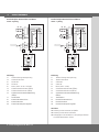
4.2 Motherboard, AS 210 B
Description:
A: Setting button OPEN (S01) /
Setting button CLOSE (S02)
X1: Terminal block for mains connection
X2: Terminal block for motor / safety circuit for drive
X3: Terminal block for command devices
X4: Terminal block for mains voltage selection
X5: Terminal block for limit switches
X6: Terminal block for 3-way switch
X7: Plug-in base for ZM SKS B circuit card
X8: Plug-in base for spiral cable
X9: Terminal block for trafc light / yard light
(only in connection with a ZM SKS B plug-in circuit card)
X10: Terminal block for press-and-release CLOSE- OPEN
X11: Terminal block for braking relay
12345678910 11 12 13 14 15
123456
1 23
PE
L1 L2 L3 UVW45
X5
X3
X1 X2
X7
12
X9
AUF ZU
X4
X8
X6
J2 J1
X10
X11
J4
J5
J3
A

GB
Door Control AS 210 B / Rev.A 1.2 – 5
5. Initial operation
5.1 General
Warning!
To guarantee that the equipment functions
properly, it must be
ensured that:
- the door is installed and operational.
- the drive motor is installed and ready for
operation.
- the command and safety devices are instal-
led and ready for operation.
- the AS 210 B controls are installed.
Information:
The relevant manufacturers’ instructions must
be adhered to for
the installation of the door, the drive motor,
and the command and safety devices.
5.2 Mains connection
Danger!
To guarantee that the controls function pro-
perly, the following points must be
ensured:
- The mains voltage must correspond to the
voltage stated on the type plate.
- For a three-phase current, a clockwise rota-
ting eld is required.
- For a permanent connection, an all-pole
main switch must be used.
- For a three-phase connection, only 3-way
automatic circuit breakers (10A) may be
used.
Detailed circuit diagram for mains connection and
motor 400 V / 3-phase
Description:
F1 Thermal fuse, control voltage
F2 Thermal overload protection for motor
K1 Protection OPEN
K2 Protection CLOSE
M Motor (400 V / 50 Hz / 3-phase)
S3 Safety limit switch OPEN
(normally closed contact)
S4 Safety limit switch CLOSE
(normally closed contact)
S7 Safety switch, emergency manual operation (normally
closed contact)
T1 Transformer
X1 Terminal block for mains connection
X2 Terminal block for motor
X4 Terminal block for mains voltage selection
5
4WVU
L3 L2 L1 PE
12 3
400V
400 V / 50 Hz

6 – Door Control AS 210 B / Rev.A 1.2
Detailed circuit diagram for mains connection and
motor 230 V / 3-phase
Description:
F1 Thermal fuse, control voltage
F2 Thermal overload protection for motor
K1 Protection OPEN
K2 Protection CLOSE
M Motor (230 V / 50 Hz / 3-phase)
S3 Safety limit switch OPEN
(normally closed contact)
S4 Safety limit switch CLOSE
(normally closed contact)
S7 Safety switch, emergency manual operation (normally
closed contact)
T1 Transformer
X1 Terminal block for mains connection
X2 Terminal block for motor
X4 Terminal block for mains voltage selection
Detailed circuit diagram for mains connection and
motor 230 V / single phase
Description:
F1 Thermal fuse, control voltage
F2 Thermal overload protection for motor
K1 Protection OPEN
K2 Protection CLOSE
M Motor (230 V / 50 Hz)
S3 Safety limit switch OPEN (normally closed contact)
S4 Safety limit switch CLOSE (normally closed contact)
S7 Safety switch, emergency manual operation (normally
closed contact)
T1 Transformer
X1 Terminal block for mains connection
X2 Terminal block for motor
X4 Terminal block for mains voltage selection
Connection:
Connect the controls to the mains power supply.
Connect the controls to the motor.
Cable groups must be xed close to their relevant terminals
using a cable tie.
5. Initial operation
5
4WVU
L3 L2 L1 PE
12 3
230V
230 V / 50 Hz
5
4NAUF ZU
LN PE
12 3
230V
230 V / 50 Hz

GB
Door Control AS 210 B / Rev.A 1.2 – 7
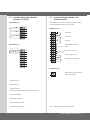
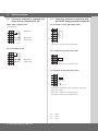
5.4 Connection arrangement for command
and safety devices
Command and safety devices can be connected via terminals
X3 and X9.
Terminal block X3
- STOP button
- OPEN button
- CLOSE button
- Closing edge safety device (CES)
9
24 V DC max. 150 mA
- Impulse input / radio
9
- Photocell barrier
9
Terminal block X9
- Potential-free connection for red
trafc light or yard light
9
9
Only in connection with an ZM SKS B plug-in circuit card
1
2
3
4
5
6
7
8
9
10
11
12
13
14
15
1
2
5
6
7
8
U
V
W
4
5
6
5
4
3
2
1
4
1
2
5.3 Connection arrangement for limit swit-
ches (terminals X5 and X2)
Terminal block X5
Terminal block X2
1
Limit switch OPEN
2
Limit switch CLOSE
4
Pre-limit switch CLOSE (after activation the door does not
reverse)
5
Thermal overload protection for motor
6
Emergency operation (normally closed contact)
7
Safety limit switch CLOSE
8
Safety limit switch OPEN

8 – Door Control AS 210 B / Rev.A 1.2
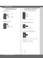
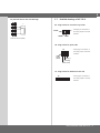
5.6 Connection examples in connection with
the ZM-SKS B plug-in module (terminal X3)
For optoelectric closing edge safety device
- DIP switch 1 must be set to the OFF position.
For 8.2 kOhm closing edge safety device
- DIP switch 1 must be set to the ON position.
For pneumatic closing edge safety device
- An 8.2 kOhm resistance must be connected in series with
the pressure switch.
- DIP switch 1 must be set to the ON position.
- DIP switch 2 must be set to the ON position.
wt: white
gr: green
br: brown
5. Initial operation
8,2
8,2
1
2
3
4
5
6
7
8
9
10
11
12
13
14
15
+12 V
Sig
GND
br
gr
wt
5.5 Connection examples for command and
safety devices (terminal block X3)
OPEN / STOP / CLOSE buttons
(4-lead solution)
- STOP button
- OPEN button
- CLOSE button
Key switch OPEN / CLOSE
- OPEN button
- CLOSE button
1
2
3
4
5
6
7
8
9
10
11
12
13
14
15
Seite laden ...
Seite laden ...
Seite laden ...
Seite laden ...
-
 1
1
-
 2
2
-
 3
3
-
 4
4
-
 5
5
-
 6
6
-
 7
7
-
 8
8
-
 9
9
-
 10
10
-
 11
11
-
 12
12
-
 13
13
-
 14
14
-
 15
15
-
 16
16
-
 17
17
-
 18
18
-
 19
19
-
 20
20
-
 21
21
-
 22
22
-
 23
23
-
 24
24


in anderen Sprachen
- English: Marantec AS 210B Owner's manual
Verwandte Papiere
-
Marantec AS 210B Bedienungsanleitung
-
Marantec CS 300 ME Bedienungsanleitung
-
-
Marantec CS 310 Bedienungsanleitung
-
-
Marantec CS 310 FU Bedienungsanleitung
-
-
-
-