Grundfos MCB 114 Installation And Operating Instructions Manual
- Typ
- Installation And Operating Instructions Manual

MCB 114 sensor input module
GRUNDFOS INSTRUCTIONS
Installation and operating instructions

2

3
MCB 114 sensor input
module
Installation and operating instructions 4
Montage- und Betriebsanleitung 6
Monterings- og driftsinstruktion 8

4
CONTENTS
Page
1. Symbols used in this document 4
2. Introduction 4
2.1 General description 4
2.2 Applications 4
2.3 References 4
3. Scope of delivery 4
4. Installation 4
4.1 Wiring diagram 4
4.2 Fitting the MCB 114 in the CUE 5
4.3 CUE displays 5
5. Service 5
5.1 Service documentation 5
6. Technical data 5
6.1 Surroundings 5
6.2 Cable length 5
6.3 Analog inputs 5
7. Disposal 5
1. Symbols used in this document
2. Introduction
This manual introduces all aspects regarding installation of your
Grundfos MCB 114 sensor input module.
2.1 General description
The MCB 114 is an analog sensor input module for the CUE.
2.2 Applications
The MCB 114 offers three additional analog inputs for the CUE:
• one analog 0/4-20 mA input for an additional sensor
• two analog Pt100/Pt1000 inputs for temperature sensors.
2.3 References
Technical documentation for Grundfos CUE:
• This manual contains all information required for installation of
the MCB 114.
• The CUE installation and operating instructions contain all
information required for putting the CUE into operation.
• The CUE data booklet contains all technical information about
the construction and applications of the CUE.
• The service instructions contain all required instructions for
dismantling and repairing the frequency converter.
Technical documentation is available on www.grundfos.com >
International website > WebCAPS.
If you have any questions, please contact the nearest Grundfos
company or service workshop.
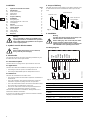
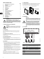
3. Scope of delivery
The MCB 114 sensor input module comes with a terminal cover,
an extended frame and an identification label to put onto the
CUE.
Fig. 1 Scope of delivery
4. Installation
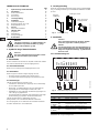
4.1 Wiring diagram
Fig. 2 Wiring diagram, MCB 114
Terminals 10, 11 and 12 are not used.
Warning
Prior to installation, read these installation and
operating instructions. Installation and operation
must comply with local regulations and accepted
codes of good practice.
Warning
If these safety instructions are not observed,
it may result in personal injury!
TM04 0026 4807
Warning
Touching the electrical parts may be fatal, even
after the CUE has been switched off.
Before making any work on the CUE, the mains
supply and other voltage inputs must be
switched off for at least as long as stated in the
CUE installation and operating instructions.
TM04 3273 3908
Terminal Type Function
1 (VDO) +24 V out Supply to sensor
2 (I IN) AI 3 Sensor 2, 0/4-20 mA
3 (GND) GND Common frame for analog input
4 (TEMP)
5 (WIRE)
AI 4 Temperature sensor 1, Pt100/Pt1000
6 (GND) GND Common frame for temperature sensor 1
7 (TEMP)
8 (WIRE)
AI 5 Temperature sensor 2, Pt100/Pt1000
9 (GND) GND Common frame for temperature sensor 2
Extended frame
Terminal cover
MCB 114 sensor
input module
1 98765432
1
2
1
1
1
0
VDO
I IN
GND
TEMP
WIRE
GND
TEMP
WIRE
GND
+
-
+

5
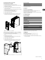
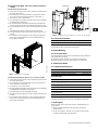
4.2 Fitting the MCB 114 in the CUE
4.2.1 Enclosures A2, A3 and B3
1. Turn off the power to the CUE. See section 4.
2. Remove the control panel, the terminal cover and the frame
from the CUE. See fig. 3.
3. Fit the MCB 114 into port B.
4. Connect the signal cables, and fasten the cables with the
enclosed cable strips.
5. Remove the knock-out plate in the extended frame so that the
MCB 114 fits under the extended frame.
6. Fit the extended frame and the terminal cover.
7. Fit the control panel in the extended frame.
8. Connect power to the CUE.
9. Set the input functions in the displays as shown in section
6.5.1 of the CUE installation and operating instructions.
Fig. 3 Enclosures A2, A3 and B3
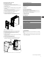
4.2.2 Enclosures A5, B1, B2, B4, C1, C2, C3, C4, D1 and D2
1. Turn off the power to the CUE. See section 4.
2. Remove the control panel and the cradle from the CUE. See
fig. 4.
3. Fit the MCB 114 into port B.
4. Connect the signal cables, and fasten the cables with the
enclosed cable strips. See fig. 4.
5. Fit the cradle and the control panel.
6. Connect power to the CUE.
7. Set the input functions in the displays as shown in section
6.5.1 of the CUE installation and operating instructions.
Fig. 4 Enclosures A5, B1, B2, B4, C1, C2, C3, C4, D1 and D2
4.3 CUE displays
For further information, see section 6.5.1 of the CUE installation
and operating instructions.
5. Service
5.1 Service documentation
Service documentation is available on www.grundfos.com >
International website > WebCAPS > Service.
If you have any questions, please contact the nearest Grundfos
company or service workshop.
6. Technical data
6.1 Surroundings
6.2 Cable length
6.3 Analog inputs
All analog inputs are galvanically separated from the supply
voltage (PELV) and other high-voltage terminals.
7. Disposal
This product or parts of it must be disposed of in an
environmentally sound way:
1. Use the public or private waste collection service.
2. If this is not possible, contact the nearest Grundfos company
or service workshop.
TM04 0025 4807TM04 0027 4807
Frame
Port B
CU
E
Cradle
Port B
Displays for reading (2.5), (2.12) and (2.13)
Displays for setting (3.16), (3.21) and (3.22)
Relative humidity 5-95 % RH
Ambient temperature during operation –10 to 55 °C
Temperature during storage and
transportation
–25 to 70 °C
Maximum length, signal cable 300 m
Analog input 3, terminal number 2
Current range 0/4-20 mA
Input resistance < 200 Ω
Analog inputs 4 and 5, terminal number 4, 5 and 7, 8
Signal type, 2- or 3-wire Pt100/Pt1000
Subject to alterations.

6
INHALTSVERZEICHNIS
Seite
1. Kennzeichnung von Hinweisen 6
2. Einleitung 6
2.1 Allgemeine Beschreibung 6
2.2 Verwendungszweck 6
2.3 Verweise 6
3. Lieferumfang 6
4. Installation 6
4.1 Schaltplan 6
4.2 Einbauen des MCB 114 in den
CUE-Frequenzumrichter 7
4.3 CUE-Bildschirmseiten 7
5. Instandhaltung 7
5.1 Serviceunterlagen 7
6. Technische Daten 7
6.1 Umgebungsbedingungen 7
6.2 Kabellänge 7
6.3 Analogeingänge 7
7. Entsorgung 7
1. Kennzeichnung von Hinweisen
2. Einleitung
Die vorliegende Betriebsanleitung beschreibt die Vorgehens-
weise zur Installation des Grundfos Sensoreingangsmoduls
MCB 114.
2.1 Allgemeine Beschreibung
Das MCB 114 ist ein Analogsensoreingangsmodul für den CUE-
Frequenzumrichter.
2.2 Verwendungszweck
Das MCB 114 bietet drei zusätzliche Analogeingänge für den
CUE-Frequenzumrichter:
• einen Analogeingang 0/4-20 mA für einen zusätzlichen Sensor
• zwei Analogeingänge Pt100/Pt1000 für Temperatursensoren.
2.3 Verweise
Technische Unterlagen für Grundfos CUE-Frequenzumrichter:
• Die vorliegende Betriebsanleitung enthält alle erforderlichen
Informationen zur Installation eines MCB 114.
• Die Betriebsanleitung vom CUE-Frequenzumrichter enthält
alle erforderlichen Informationen zur Inbetriebnahme des
CUE-Frequenzumrichters.
• Das Datenheft vom CUE-Frequenzumrichter enthält alle tech-
nischen Informationen zum Aufbau und Anwendungsbereich
des CUE-Frequenzumrichters.
• Die Serviceanleitungen enthalten alle erforderlichen Anwei-
sungen zum Zerlegen und Reparieren des CUE-Frequenzum-
richters.
Die technischen Unterlagen sind auf auf der Internetseite
www.grundfos.de unter WebCAPS verfügbar.
Bei weiteren Fragen wenden Sie sich bitte an die nächste
Grundfos Niederlassung oder autorisierte Servicewerkstatt.
3. Lieferumfang
Zum Lieferumfang des Sensoreingangsmoduls MCB 114 gehören
eine Klemmenabdeckung, ein Erweiterungsrahmen und ein
Typenaufkleber zum Anbringen am CUE-Frequenzumrichter.
Abb. 1 Lieferumfang
4. Installation
4.1 Schaltplan
Abb. 2 Schaltplan, MCB 114
Klemmen 10, 11 und 12 werden nicht verwendet.
Warnung
Vor der Installation ist diese Montage- und
Betriebsanleitung zu lesen. Die Montage und der
Betrieb müssen in Übereinstimmung mit den ört-
lichen Vorschriften und den anerkannten Regeln
der Technik erfolgen.
Warnung
Wenn diese Sicherheitshinweise nicht beachtet
werden, kann dies Personenschäden zur Folge
haben!
TM04 0026 4807
Warnung
Das Berühren der elektrischen Bauteile kann zum
Tod oder zu schweren Verletzungen führen, auch
wenn der CUE-Frequenzumrichter ausgeschaltet
ist.
Vor Arbeiten an dem CUE-Frequenzumrichter
sind die Netzspannung und andere Spannungs-
versorgungen abzuschalten. Bevor mit den
Arbeiten begonnen werden darf, ist unbedingt die
in der Betriebsanleitung des CUE-Frequenzum-
richters angegebene Mindestwartezeit abzuwar-
ten.
TM04 3273 3908
Klemme Typ Funktion
1 (VDO)
+24 V
Ausgang
Spannungsversorgung zum Sensor
2 (I IN) AI 3 Sensor 2, 0/4-20 mA
3 (GND) Masse Gehäusemasse für Analogeingang
4 (TEMP)
5 (WIRE)
AI 4 Temperatursensor 1, Pt100/Pt1000
6 (GND) Masse Gehäusemasse für Temperatursensor 1
7 (TEMP)
8 (WIRE)
AI 5 Temperatursensor 2, Pt100/Pt1000
9 (GND) Masse Gehäusemasse für Temperatursensor 2
Erweiterungsrahmen
Klemmenabdeckung
Sensoreingangs-
modul MCB 114
1 98765432
1
2
1
1
1
0
VDO
I IN
GND
TEMP
WIRE
GND
TEMP
WIRE
GND
+
-
+

7
4.2 Einbauen des MCB 114 in den CUE-Frequenzum-
richter
4.2.1 Gehäuse A2, A3 und B3
1. Spannungsversorgung zum CUE-Frequenzumrichter abschal-
ten. Siehe Abschnitt 4.
2. Das Bedienfeld, die Klemmenabdeckung und den Rahmen
vom CUE-Frequenzumrichter abnehmen. Siehe Abb. 3.
3. Das MCB 114 in Port B einsetzen.
4. Die Signalkabel anschließen und die Kabel mit den beigefüg-
ten Kabelbindern befestigen.
5. Die Ausbrechplatte im Erweiterungsrahmen herausbrechen,
so dass das MCB 114 unter den Erweiterungsrahmen passt.
6. Den Erweiterungsrahmen und die Klemmenabdeckung anbrin-
gen.
7. Das Bedienfeld in den Erweiterungsrahmen einsetzen.
8. Die Spannungsversorgung zum CUE-Frequenzumrichter ein-
schalten.
9. Die Funktion für die Eingänge in dem entsprechenden Bild-
schirm wie im Abschnitt 6.5.1 der CUE-Betriebsanleitung
beschrieben auswählen.
Abb. 3 Gehäuse A2, A3 und B3
4.2.2 Gehäuse A5, B1, B2, B4, C1, C2, C3, C4, D1 und D2
1. Spannungsversorgung zum CUE-Frequenzumrichter abschal-
ten. Siehe Abschnitt 4.
2. Die Frontplatte und das Bedienfeld vom CUE-Frequenzum-
richter abnehmen. Siehe Abb. 4.
3. Das MCB 114 in Port B einsetzen.
4. Die Signalkabel anschließen und die Kabel mit den beigefüg-
ten Kabelbindern befestigen. Siehe Abb. 2.
5. Das Bedienfeld und die Frontplatte einsetzen.
6. Die Spannungsversorgung zum CUE-Frequenzumrichter ein-
schalten.
7. Die Funktion für die Eingänge in dem entsprechenden Bild-
schirm wie im Abschnitt 6.5.1 der CUE-Betriebsanleitung
beschrieben auswählen.
Abb. 4 Gehäuse A5, B1, B2, B4, C1, C2, C3, C4, D1 und D2
4.3 CUE-Bildschirmseiten
Weitere Informationen finden Sie in der Montage- und Bedie-
nungsanleitung des CUE-Frequenzumrichters.
5. Instandhaltung
5.1 Serviceunterlagen
Serviceunterlagen sind auf auf der Internetseite www.grundfos.de
unter WebCAPS verfügbar.
Bei weiteren Fragen wenden Sie sich bitte an die nächste
Grundfos Niederlassung oder autorisierte Servicewerkstatt.
6. Technische Daten
6.1 Umgebungsbedingungen
6.2 Kabellänge
6.3 Analogeingänge
Alle Analogeingänge sind galvanisch von der Versorgungsspan-
nung (PELV) und anderen Hochspannungsklemmen getrennt.
7. Entsorgung
Dieses Produkt sowie Teile davon müssen umweltgerecht ent-
sorgt werden:
1. Nutzen Sie die öffentlichen oder privaten Entsorgungs-
gesellschaften.
2. Ist das nicht möglich, wenden Sie sich bitte an die nächste
Grundfos Gesellschaft oder Werkstatt.
TM04 0025 4807
Rahmen
Port B
TM04 0027 4807
Bildschirmseiten zum Auslesen (2.5), (2.12) und (2.13)
Bildschirmseiten zum Einstellen (3.16), (3.21) und (3.22)
Relative Luftfeuchtigkeit 5-95 %
Umgebungstemperatur im Betrieb –10 bis 55 °C
Temperatur für Lagerung und Transport –25 bis 70 °C
Max. zul. Kabellänge, Signalkabel 300 m
Analogeingang 3, Klemmennummer 2
Strombereich 0/4-20 mA
Eingangswiderstand < 200 Ω
Analogeingänge 4 und 5,
Klemmennummer
4, 5 und 7, 8
Signalart, 2- oder 3-adrig Pt100/Pt1000
CU
E
Bedienfeld
Port B
Technische Änderungen vorbehalten.

8
INDHOLDSFORTEGNELSE
Side
1. Symboler brugt i dette dokument 8
2. Introduktion 8
2.1 Generel beskrivelse 8
2.2 Anvendelse 8
2.3 Henvisninger 8
3. Leveringsomfang 8
4. Installation 8
4.1 Forbindelsesdiagram 8
4.2 Montering af MCB 114 i CUE 9
4.3 Displaybilleder til CUE 9
5. Service 9
5.1 Servicedokumentation 9
6. Tekniske data 9
6.1 Omgivelser 9
6.2 Kabellængde 9
6.3 Analoge indgange 9
7. Bortskaffelse 9
1. Symboler brugt i dette dokument
2. Introduktion
Denne instruktion introducerer alle aspekter vedrørende installa-
tion af dit Grundfos MCB 114-sensorindgangsmodul.
2.1 Generel beskrivelse
MCB 114 er et analogt sensorindgangsmodul til CUE.
2.2 Anvendelse
MCB 114 giver tre ekstra analoge indgange til CUE:
• ét analogt 0/4-20 mA-indgang til en ekstra sensor
• to analoge Pt100/Pt1000-indgange til temperatursensorer.
2.3 Henvisninger
Teknisk dokumentation til Grundfos CUE:
• Instruktionen indeholder alle oplysninger der er nødvendige
for at installere MCB 114.
• Monterings- og driftsinstruktionen til CUE indeholder alle
oplysninger der er nødvendige for sætte CUE i drift.
• Datahæftet for CUE indeholder alle tekniske oplysninger om
CUE’s design og applikationer.
• Serviceinstruktionen indeholder alle nødvendige anvisninger
på demontering og reparation af frekvensomformeren.
Teknisk dokumentation er tilgængelig online på
www.grundfos.com > International website > WebCAPS.
Har du spørgsmål, er du velkommen til at kontakte nærmeste
Grundfos-selskab eller -serviceværksted.
3. Leveringsomfang
MCB 114-sensorindgangsmodulet leveres med en klemmeafdæk-
ning, en forlænget ramme og en identifikationsmærkat til at sætte
på CUE.
Fig. 1 Leveringsomfang
4. Installation
4.1 Forbindelsesdiagram
Fig. 2 Forbindelsesdiagram, MCB 114
Klemmerne 10, 11 og 12 bruges ikke.
Advarsel
Læs denne monterings- og driftsinstruktion før
installation. Følg lokale forskrifter og gængs
praksis ved installation og drift.
Advarsel
Hvis disse sikkerhedsanvisninger ikke overhol-
des, kan det medføre personskade!
TM04 0026 4807
Advarsel
Det er forbundet med livsfare at berøre strømfø-
rende dele, også efter at netforsyningen er
afbrudt.
Før ethvert indgreb i CUE skal netspændingen og
andre spændingstilgange være afbrudt mindst så
længe som angivet i monterings- og driftsinstruk-
tionen for CUE.
TM04 3273 3908
Klemme Type Funktion
1 (VDO) +24 V ud Forsyning til sensor
2 (I IN) AI 3 Sensor 2, 0/4-20 mA
3 (GND) GND Fælles stel for analog indgang
4 (TEMP)
5 (WIRE)
AI 4 Temperatursensor 1, Pt100/Pt1000
6 (GND) GND Fælles stel for temperatursensor 1
7 (TEMP)
8 (WIRE)
AI 5 Temperatursensor 2, Pt100/Pt1000
9 (GND) GND Fælles stel for temperatursensor 2
Forlænget ramme
Klemme-
afdækning
MCB 114-sensor-
indgangsmodul
1 98765432
1
2
1
1
1
0
VDO
I IN
GND
TEMP
WIRE
GND
TEMP
WIRE
GND
+
-
+

9
4.2 Montering af MCB 114 i CUE
4.2.1 Kapsling A2, A3 og B3
1. Afbryd forsyningsspændingen til CUE. Se afsnit 4.
2. Fjern betjeningspanelet, klemmeafdækningen og rammen fra
CUE. Se fig. 3.
3. Sæt MCB 114 i port B.
4. Tilslut signalkablerne, og fastgør kablerne med den vedlagte
kabelstrips.
5. Fjern udslagspladen i den forlængede ramme så MCB 114
passer under den forlængede ramme.
6. Montér den forlængede ramme og klemmeafdækningen.
7. Sæt betjeningspanelet i den forlængede ramme.
8. Tilslut forsyningsspændingen til CUE.
9. Indstil indgangsfunktionerne i displaybillederne som vist i
afsnit 6.5.1 i monterings- og driftsinstruktionen til CUE.
Fig. 3 Kapsling A2, A3 og B3
4.2.2 Kapsling A5, B1, B2, B4, C1, C2, C3, C4, D1 og D2
1. Afbryd forsyningsspændingen til CUE. Se afsnit 4.
2. Fjern betjeningspanelet og holderen fra CUE. Se fig. 4.
3. Sæt MCB 114 i port B.
4. Tilslut signalkablerne, og fastgør kablerne med den vedlagte
kabelstrips. Se fig. 2.
5. Montér holderen og betjeningspanelet.
6. Tilslut forsyningsspændingen til CUE.
7. Indstil indgangsfunktionerne i displaybillederne som vist i
afsnit 6.5.1 i monterings- og driftsinstruktionen til CUE.
Fig. 4 Kapsling A5, B1, B2, B4, C1, C2, C3, C4, D1 og D2
4.3 Displaybilleder til CUE
Yderligere oplysninger, se afsnit 6.5.1 i monterings- og driftsin-
struktionen til CUE.
5. Service
5.1 Servicedokumentation
Servicedokumentation er tilgængelig på www.grundfos.com >
International website > WebCAPS > Service.
Har du spørgsmål, er du velkommen til at kontakte nærmeste
Grundfos-selskab eller -serviceværksted.
6. Tekniske data
6.1 Omgivelser
6.2 Kabellængde
6.3 Analoge indgange
Alle analoge indgange er galvanisk adskilt fra forsyningsspæn-
dingen (PELV) og andre højspændingsklemmer.
7. Bortskaffelse
Dette produkt eller dele deraf skal bortskaffes på en miljørigtig
måde:
1. Brug de offentlige eller godkendte, private renovationsordnin-
ger.
2. Hvis det ikke er muligt, kontakt nærmeste Grundfos-selskab
eller -serviceværksted.
TM04 0025 4807TM04 0027 4807
Ramme
Port B
CU
E
Holder
Port B
Displaybilleder til aflæsning (2.5), (2.12) og (2.13)
Displaybilleder til indstilling (3.16), (3.21) og (3.22)
Relativ luftfugtighed 5-95 % RH
Omgivelsestemperatur under drift –10 til 55 °C
Temperatur ved opbevaring og transport –25 til 70 °C
Maks. længde, signalkabel 300 m
Analog indgang 3, klemmenummer 2
Strømområde 0/4-20 mA
Indgangsmodstand < 200 Ω
Analoge indgange 4 og 5, klemmenummer 4, 5 og 7, 8
Signaltype, 2 eller 3 ledere Pt100/Pt1000
Ret til ændringer forbeholdes.

Argentina
Bombas GRUNDFOS de Argentina S.A.
Ruta Panamericana km. 37.500 Lote
34A
1619 - Garin
Pcia. de Buenos Aires
Phone: +54-3327 414 444
Telefax: +54-3327 411 111
Australia
GRUNDFOS Pumps Pty. Ltd.
P.O. Box 2040
Regency Park
South Australia 5942
Phone: +61-8-8461-4611
Telefax: +61-8-8340 0155
Austria
GRUNDFOS Pumpen Vertrieb
Ges.m.b.H.
Grundfosstraße 2
A-5082 Grödig/Salzburg
Tel.: +43-6246-883-0
Telefax: +43-6246-883-30
Belgium
N.V. GRUNDFOS Bellux S.A.
Boomsesteenweg 81-83
B-2630 Aartselaar
Tél.: +32-3-870 7300
Télécopie: +32-3-870 7301
Belorussia
Представительство ГРУНДФОС в
Минске
220123, Минск,
ул. В. Хоружей, 22, оф. 1105
Тел.: +(37517) 233 97 65,
Факс: +(37517) 233 97 69
E-mail: grund[email protected]
Bosnia/Herzegovina
GRUNDFOS Sarajevo
Trg Heroja 16,
BiH-71000 Sarajevo
Phone: +387 33 713 290
Telefax: +387 33 659 079
e-mail: grundfos@bih.net.ba
Brazil
Mark GRUNDFOS Ltda.
Av. Humberto de Alencar Castelo
Branco, 630
CEP 09850 - 300
São Bernardo do Campo - SP
Phone: +55-11 4393 5533
Telefax: +55-11 4343 5015
Bulgaria
GRUNDFOS Pumpen Vertrieb
Representative Office - Bulgaria
Bulgaria, 1421 Sofia
Lozenetz District
105-107 Arsenalski blvd.
Phone: +359 2963 3820, 2963 5653
Telefax: +359 2963 1305
Canada
GRUNDFOS Canada Inc.
2941 Brighton Road
Oakville, Ontario
L6H 6C9
Phone: +1-905 829 9533
Telefax: +1-905 829 9512
China
GRUNDFOS Pumps (Shanghai) Co. Ltd.
51 Floor, Raffles City
No. 268 Xi Zang Road. (M)
Shanghai 200001
PRC
Phone: +86-021-612 252 22
Telefax: +86-021-612 253 33
Croatia
GRUNDFOS predstavništvo Zagreb
Cebini 37, Buzin
HR-10010 Zagreb
Phone: +385 1 6595 400
Telefax: +385 1 6595 499
Czech Republic
GRUNDFOS s.r.o.
Čajkovského 21
779 00 Olomouc
Phone: +420-585-716 111
Telefax: +420-585-716 299
Denmark
GRUNDFOS DK A/S
Martin Bachs Vej 3
DK-8850 Bjerringbro
Tlf.: +45-87 50 50 50
Telefax: +45-87 50 51 51
E-mail: info_GDK@grundfos.com
www.grundfos.com/DK
Estonia
GRUNDFOS Pumps Eesti OÜ
Peterburi tee 92G
11415 Tallinn
Tel: + 372 606 1690
Fax: + 372 606 1691
Finland
OY GRUNDFOS Pumput AB
Mestarintie 11
FIN-01730 Vantaa
Phone: +358-3066 5650
Telefax: +358-3066 56550
France
Pompes GRUNDFOS Distribution S.A.
Parc d’Activités de Chesnes
57, rue de Malacombe
F-38290 St. Quentin Fallavier (Lyon)
Tél.: +33-4 74 82 15 15
Télécopie: +33-4 74 94 10 51
Germany
GRUNDFOS GMBH
Schlüterstr. 33
40699 Erkrath
Tel.: +49-(0) 211 929 69-0
Telefax: +49-(0) 211 929 69-3799
e-mail: infoservice@grundfos.de
Service in Deutschland:
e-mail: kundendienst@grundfos.de
Greece
GRUNDFOS Hellas A.E.B.E.
20th km. Athinon-Markopoulou Av.
P.O. B o x 7 1
GR-19002 Peania
Phone: +0030-210-66 83 400
Telefax: +0030-210-66 46 273
Hong Kong
GRUNDFOS Pumps (Hong Kong) Ltd.
Unit 1, Ground floor
Siu Wai Industrial Centre
29-33 Wing Hong Street &
68 King Lam Street, Cheung Sha Wan
Kowloon
Phone: +852-27861706 / 27861741
Telefax: +852-27858664
Hungary
GRUNDFOS Hungária Kft.
Park u. 8
H-2045 Törökbálint,
Phone: +36-23 511 110
Telefax: +36-23 511 111
India
GRUNDFOS Pumps India Private Lim-
ited
118 Old Mahabalipuram Road
Thoraipakkam
Chennai 600 096
Phone: +91-44 2496 6800
Indonesia
PT GRUNDFOS Pompa
Jl. Rawa Sumur III, Blok III / CC-1
Kawasan Industri, Pulogadung
Jakarta 13930
Phone: +62-21-460 6909
Telefax: +62-21-460 6910 / 460 6901
Ireland
GRUNDFOS (Ireland) Ltd.
Unit A, Merrywell Business Park
Ballymount Road Lower
Dublin 12
Phone: +353-1-4089 800
Telefax: +353-1-4089 830
Italy
GRUNDFOS Pompe Italia S.r.l.
Via Gran Sasso 4
I-20060 Truccazzano (Milano)
Tel.: +39-02-95838112
Telefax: +39-02-95309290 / 95838461
Japan
GRUNDFOS Pumps K.K.
Gotanda Metalion Bldg., 5F,
5-21-15, Higashi-gotanda
Shiagawa-ku, Tokyo
141-0022 Japan
Phone: +81 35 448 1391
Telefax: +81 35 448 9619
Korea
GRUNDFOS Pumps Korea Ltd.
6th Floor, Aju Building 679-5
Yeoksam-dong, Kangnam-ku, 135-916
Seoul, Korea
Phone: +82-2-5317 600
Telefax: +82-2-5633 725
Latvia
SIA GRUNDFOS Pumps Latvia
Deglava biznesa centrs
Augusta Deglava ielā 60, LV-1035, Rīga,
Tālr.: + 371 714 9640, 7 149 641
Fakss: + 371 914 9646
Lithuania
GRUNDFOS Pumps UAB
Smolensko g. 6
LT-03201 Vilnius
Tel: + 370 52 395 430
Fax: + 370 52 395 431
Malaysia
GRUNDFOS Pumps Sdn. Bhd.
7 Jalan Peguam U1/25
Glenmarie Industrial Park
40150 Shah Alam
Selangor
Phone: +60-3-5569 2922
Telefax: +60-3-5569 2866
México
Bombas GRUNDFOS de México S.A. de
C.V.
Boulevard TLC No. 15
Parque Industrial Stiva Aeropuerto
Apodaca, N.L. 66600
Phone: +52-81-8144 4000
Telefax: +52-81-8144 4010
Netherlands
GRUNDFOS Netherlands
Veluwezoom 35
1326 AE Almere
Postbus 22015
1302 CA ALMERE
Tel.: +31-88-478 6336
Telefax: +31-88-478 6332
e-mail: info_gnl@grundfos.com
New Zealand
GRUNDFOS Pumps NZ Ltd.
17 Beatrice Tinsley Crescent
North Harbour Industrial Estate
Albany, Auckland
Phone: +64-9-415 3240
Telefax: +64-9-415 3250
Norway
GRUNDFOS Pumper A/S
Strømsveien 344
Postboks 235, Leirdal
N-1011 Oslo
Tlf.: +47-22 90 47 00
Telefax: +47-22 32 21 50
Poland
GRUNDFOS Pompy Sp. z o.o.
ul. Klonowa 23
Baranowo k. Poznania
PL-62-081 Przeźmierowo
Tel: (+48-61) 650 13 00
Fax: (+48-61) 650 13 50
Portugal
Bombas GRUNDFOS Portugal, S.A.
Rua Calvet de Magalhães, 241
Apartado 1079
P-2770-153 Paço de Arcos
Tel.: +351-21-440 76 00
Telefax: +351-21-440 76 90
România
GRUNDFOS Pompe România SRL
Bd. Biruintei, nr 103
Pantelimon county Ilfov
Phone: +40 21 200 4100
Telefax: +40 21 200 4101
E-mail: romania@grundfos.ro
Russia
ООО Грундфос
Россия, 109544 Москва, ул. Школьная
39
Тел. (+7) 495 737 30 00, 564 88 00
Факс (+7) 495 737 75 36, 564 88 11
E-mail
grundfos.moscow@grundfos.com
Serbia
GRUNDFOS Predstavništvo Beograd
Dr. Milutina Ivkovića 2a/29
YU-11000 Beograd
Phone: +381 11 26 47 877 / 11 26 47
496
Telefax: +381 11 26 48 340
Singapore
GRUNDFOS (Singapore) Pte. Ltd.
24 Tuas West Road
Jurong Town
Singapore 638381
Phone: +65-6865 1222
Telefax: +65-6861 8402
Slovenia
GRUNDFOS PUMPEN VERTRIEB
Ges.m.b.H.,
Podružnica Ljubljana
Šlandrova 8b, SI-1231 Ljubljana-Črnuče
Phone: +386 1 568 0610
Telefax: +386 1 568 0619
E-mail: slovenia@grundfos.si
Spain
Bombas GRUNDFOS España S.A.
Camino de la Fuentecilla, s/n
E-28110 Algete (Madrid)
Tel.: +34-91-848 8800
Telefax: +34-91-628 0465
Sweden
GRUNDFOS AB
Box 333 (Lunnagårdsgatan 6)
431 24 Mölndal
Tel.: +46(0)771-32 23 00
Telefax: +46(0)31-331 94 60
Switzerland
GRUNDFOS Pumpen AG
Bruggacherstrasse 10
CH-8117 Fällanden/ZH
Tel.: +41-1-806 8111
Telefax: +41-1-806 8115
Taiwan
GRUNDFOS Pumps (Taiwan) Ltd.
7 Floor, 219 Min-Chuan Road
Taich un g, Ta iw an, R. O.C.
Phone: +886-4-2305 0868
Telefax: +886-4-2305 0878
Thailand
GRUNDFOS (Thailand) Ltd.
92 Chaloem Phrakiat Rama 9 Road,
Dokmai, Pravej, Bangkok 10250
Phone: +66-2-725 8999
Telefax: +66-2-725 8998
Turkey
GRUNDFOS POMPA San. ve Tic. Ltd.
Sti.
Gebze Organize Sanayi Bölgesi
Ihsan dede Caddesi,
2. yol 200. Sokak No. 204
41490 Gebze/ Kocaeli
Phone: +90 - 262-679 7979
Telefax: +90 - 262-679 7905
E-mail: satis@grundfos.com
Ukraine
ТОВ ГРУНДФОС УКРАЇНА
01010 Київ, Вул. Московська 8б,
Тел.:(+38 044) 390 40 50
Фах.: (+38 044) 390 40 59
E-mail: ukraine@grundfos.com
United Arab Emirates
GRUNDFOS Gulf Distribution
P.O. Box 16768
Jebel Ali Free Zone
Dubai
Phone: +971-4- 8815 166
Telefax: +971-4-8815 136
United Kingdom
GRUNDFOS Pumps Ltd.
Grovebury Road
Leighton Buzzard/Beds. LU7 8TL
Phone: +44-1525-850000
Telefax: +44-1525-850011
U.S.A.
GRUNDFOS Pumps Corporation
17100 West 118th Terrace
Olathe, Kansas 66061
Phone: +1-913-227-3400
Telefax: +1-913-227-3500
Usbekistan
Представительство ГРУНДФОС в
Ташкенте
700000 Ташкент ул.Усмана Носира 1-й
тупик 5
Телефон: (3712) 55-68-15
Факс: (3712) 53-36-35
Addresses revised 02.04.2009

www.grundfos.com
Being responsible is our foundation
Thinking ahead makes it possible
Innovation is the essence
96794550 0609
21
Repl. 96794550 1008
-
 1
1
-
 2
2
-
 3
3
-
 4
4
-
 5
5
-
 6
6
-
 7
7
-
 8
8
-
 9
9
-
 10
10
-
 11
11


Grundfos MCB 114 Installation And Operating Instructions Manual
- Typ
- Installation And Operating Instructions Manual
in anderen Sprachen
- English: Grundfos MCB 114
- dansk: Grundfos MCB 114
Verwandte Artikel
-
Grundfos EMC filter Installation And Operating Instructions Manual
-
-
-
-
-
-
-
-
-