
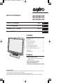
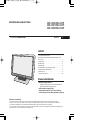
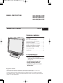
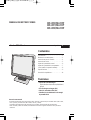
INSTRUCTION MANUAL
VMC-L1015/VMC-L1015P
VMC-L1017/VMC-L1017P
VMC-L1019/VMC-L1019P
Color TFT LCD monitor
English
GB
TFT-LCD-Farbmonitor
Deutsch
D
Moniteur LCD TFT couleurs
Français
F
Monitor TFT LCD color
Español
E
Contents
Information to user. . . . . . . . . . . . . . . . . . . . . . 1
Precautions . . . . . . . . . . . . . . . . . . . . . . . . . . . 2
Names of controls/parts. . . . . . . . . . . . . . . . . . 3
Connection instructions. . . . . . . . . . . . . . . . . . 5
Instructions for use . . . . . . . . . . . . . . . . . . . . . 6
Monitoring display adjustment. . . . . . . . . . . . . 7
Computer display adjustment . . . . . . . . . . . . . 8
How to install the mounting bracket. . . . . . . . . 9
Specifications . . . . . . . . . . . . . . . . . . . . . . . . 10
Troubleshooting. . . . . . . . . . . . . . . . . . . . . . . 11
Features
• Multilingual menu support
English/Chinese/French/German/Spanish/
Italian/Japanese
• Picture in Picture (PIP) function
• NTSC/PAL automatic select
• VESA Display Power Management Signaling
About this manual
• This manual gives basic connections and operations instructions for 3 NTSC models (VMC-L1015, L1017 and L1019)
and 3 PAL models (VMC-L1015P, L1017P and L1019P).
For more information on models variations, please refer to the specifications page.
• Before installing and using this unit, please read this manual carefully. Be sure to keep it handy for later reference.

Information to user
1
English
CAUTION
RISK OF ELECTRIC SHOCK
DO NOT OPEN
CAUTION: TO REDUCE THE RISK OF
ELECTRIC SHOCK, DO NOT REMOVE
COVER (OR BACK). NO USER-
SERVICEABLE PARTS INSIDE. REFER
SERVICING TO QUALIFIED SERVICE
PERSONNEL.
WARNING: To reduce the risk of fire or electric shock,
do not expose this appliance to rain or moisture.
CAUTION: Changes or modifications not expressly
approved by the manufacturer may void the user’s
authority to operate this equipment.
The lightning flash with arrowhead symbol,
within an equilateral triangle, is intended to
alert the user to the presence of uninsulated
“dangerous voltage” within the product’s
enclosure that may be of sufficient magnitude
to constitute a risk of electric shock to
persons.
The exclamation point within an equilateral
triangle is intended to alert the user to the
presence of important operating and
maintenance (servicing) instructions in the
literature accompanying the product.
This equipment has been tested and found to
comply with the limits for a Class B digital device,
pursuant to part 15 of the FCC Rules.
These limits are designed to provide reasonable
protection against harmful interference in a
residential installation. This equipment
generated, uses and can radiate radio frequency
energy and, if not installed and used in
accordance with the instructions, may cause
harmful interference to radio communications.
However, there is no guarantee that interference
will not occur in a particular installation.
If this equipment does cause harmful
interference radio or television reception, which
can be determined by turning the equipment off
and on, the user is encouraged to try to correct
the interference by one or more of the following
measures:
• Reorient or relocate the receiving antenna.
• Increase the separation between the
equipment and receiver.
For the customers in Canada
This class B digital apparatus complies with Canadian
ICES-003.
CAUTION
Danger of explosion if battery is incorrectly replaced.
Replace only with the same or equivalent type
recommended by the manufacturer.
Discard used batteries according to the manufacture’s
instructions.
Declaration of Conformity
Model Number : VMC-L1019, L1017, L1015
Trade Name : SANYO
Responsible party : SANYO FISHER
COMPANY
Address : 21605 Plummer Street,
Chatsworth, California
91311
Telephone No. : (818) 998-7322
• This device complies with Part 15 of the FCC
Rules.
Operation is subject to the following two
conditions:
(1) this device may not cause harmful
interference,and
(2) this device must accept any interference
received, including interference that may
cause undesired operation.
• Connect the equipment into an outlet on a
circuit different from that to which the receiver
is connected.
• Consult the dealer or an experienced radio/TV
technician for help.
Safety Guard (USA only)

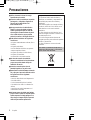
Precautions
2
English
Please note:
Your SANYO product is designed and
manufactured with high quality materials and
components which can be recycled and
reused.
This symbol means that electrical and
electronic equipment, at their end-of-life, should
be disposed of separately from your household
waste.
Please dispose of this equipment at your local
community waste collection/recycling centre.
In the European Union there are separate
collection systems for used electrical and
electronic products.
Please help us to conserve the environment we
live in!
This symbol mark and recycle system are
applied only to EU countries and not applied to
the countries in the other area of the world.
■ Use only the power source specified on the
unit.
■ When not using this unit for a long period
of time, or when cleaning it, be sure to
disconnect the power plug from the AC
outlet.
■ Do not allow anything to rest on the power
cord. And do not place this unit where
people will tread on the cord. Do not
overload wall outlets or power cords as
this can result in a fire or electric shock.
■ Avoid using this unit under the following
conditions:
- in extremely hot, cold or humid places,
- in dusty places,
- near appliances generating strong magnetic
fields,
- in places subject to direct sunlight,
- in badly ventilated places,
- in automobiles with doors closed.
■ Do not cover the ventilation slots while in
operation as this could obstruct the
required ventilation flow.
■ When dust accumulates on the screen
surface, clean it with a soft cloth.
■ Unplug this unit from the AC outlet and
refer servicing to qualified service
personnel under the following conditions:
- when the power cord is frayed or the plug is
damaged,
- if liquid has been spilled into the unit,
- if the unit has been dropped or the cabinet
has been damaged,
- when the unit exhibits a distinct change in
performance.
■ Do not attempt to service this unit yourself
as opening or removing covers may
expose you to dangerous voltage or other
hazards. Always refer servicing to qualified
service personnel.
Important (U.K. only)
Connect the mains lead to a suitable plug
following the colour code:
• Blue wire (Neutral) → to plug pin N or
coloured black
• Brown wire (Live) → to plug pin L or
coloured red
• Green and Yellow wire (Earth) → to plug
pin E or “ ”
Do not connect Blue and Brown wire onto plug
pin E or onto earth symbol “ ”.

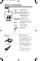
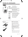
Names of controls/parts
3
English
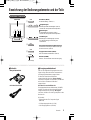
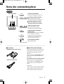
Front view
MODE
AUTO
MENU
POWER
Viewing area
q
w
e
r y
t
Adjustment control (MENU)
For fine adjustment. (Pages 7, 8)
Brightness adjustment control
Adjusts the brightness of the screen. (Page 6)
• Select the appropriate menu item.
Contrast adjustment control
For adjusting the screen contrast. (Page 6)
• Select the appropriate menu item.
Volume adjustment control
Adjusts the volume level. (Page 6)
• For adjustment, change the setting value.
Automatic display adjustment control (AUTO)
Automatically adjusts the screen (for use with VGA
connections). (Page 6)
Input mode control (MODE)
Changes the input mode. (Page 6)
Power button (POWER)
Tur ns the power on or off.
w
e
q
r
t
y
Power
indicator
light
When no signals are being input to any of the
following input terminals, the monitor switches
automatically to power saving mode.
The screen will switch to a blue screen (“Power
Saving” will appear after approximately 10
seconds), and then it will switch to a black
screen.
To cancel power saving mode, press the
POWER button twice. The screen will switch to a
blue screen and “No signal” will appear, so
connect a signal source to the terminals.
(Rear view)
• Composite signal input terminal (BNC IN)
• S Video signal input terminal (Y/C IN)
• VGA signal input terminal (VGA IN)
■Accessories
• AC adapter/AC cord
• VGA connecting cable
■Power saving mode

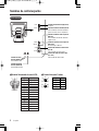
Names of controls/parts
4
English
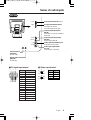
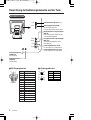
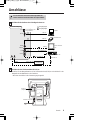
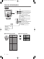
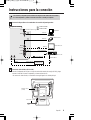
Rear view
BNC IN
DC IN
VGA IN
BNC OUT
Y/C IN
Y/C OUT
AUDIO OUT AUDIO IN
VGA signal input terminal (VGA IN)
For the input of a computer
VGA (Video Graphics Array) signal.
S-Video signal input terminal (Y/C IN)
For the input of S-Video signal.
Audio-In terminal
(AUDIO IN)
For audio input.
S-Video signal output terminal
(Y/C OUT)
For the output of S-Video signal.
Audio-Out terminal
(AUDIO OUT)
For audio output.
Power input terminal (DC IN)
(Page 5)
Composite signal input terminal
(BNC IN)
For the input of CCD camera surveillance
image signal.
Composite signal output terminal
(BNC OUT)
Sends the image to BNC IN.
■VGA signal input terminal
Signal
Red signal
Green signal
Blue signal
No use
No use
GND (Red)
GND (Green)
GND (Blue)
No use
GND (sync)
No use
SDA
H sync
V sync
SCL
q
w
e
r
t
y
u
i
o
!0
!1
!2
!3
!4
!5
Pin No.
qet
!5 !4 !3 !2 !1
!0 oiuy
rw
■S-Video signal terminal
OUT
IN
w
r
w
r
q
e
q
e
Pin No.
q
w
e
r
Signal
GND (Y)
GND (C)
Y
C

Connection instructions
5
English
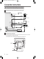
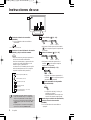
• When connecting, ensure the power supply to each unit is switched off.
• The other devices and connection cables required are sold separately.
BNC IN
DC IN
VGA IN
BNC OUT
Y/C IN
Y/C OUT
AUDIO OUT AUDIO IN
Monitor TV etc.
Hard-disk recorder etc.
AUDIO LINE IN
VGA OUT
BNC OUT
Y/C (S-VIDEO) OUT
Y/C (S-VIDEO) IN
AUDIO LINE OUT
BNC IN
CCD Camera etc.
(Included VGAconnecting cable)
Computer
: Input signal
: Output signal
Amplifier etc.
Connection example
(Refer to x for steps.)
Connect the devices to the connection terminals at the rear panel.
1
AC adapter
(included)
AC cord (Included)
Connect the power cord (DC 12V).
2
Connect the included AC adapter plug to the power input terminal (DC IN), and then connect the
AC cord between the AC adapter and AC outlet.
• Once the power cord is connected, the power supply will reach the main unit.

Instructions for use
6
English
POWERMODEAUTOMENU
1 5
2
43
2
A
B
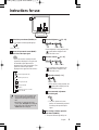
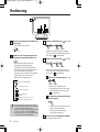
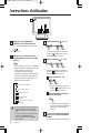
Switch the power button (POWER) on.
e The power indicator light will light up.
Press the input mode control (MODE)
and choose the input signal.
• Press once and the currently selected
signal will be displayed. Press again and
the available signal options will be
displayed in the order shown below. (The
symbol for selected option will be
displayed in the upper left of the screen.)
: VGA signal (VGA IN)
: DVI signal (DVI IN)
Optional
: Composite signal (BNC IN)
: S-Video signal (Y/C IN)
: Component signal (Y, Cb, Cr IN)
Cannot be used
MODE
2
POWER
Power indicator light
1
• When the signal is changed, initially a blue
screen will be displayed, followed by the
display of the chosen signal 2-3 seconds
later.
• When there is no input detected on the
chosen signal, “No signal” will be displayed.
• If the power to the connected device is off,
“Video Loss” will be displayed.
Adjust the brightness ( ) [0 – 51].
• As the brightness is being adjusted, the
symbol will be displayed in the
upper left of the screen.
Adjust the contrast ( ) [0 – 51].
• As the contrast is being adjusted, the
symbol will be displayed in the
upper left of the screen.
Adjust the volume [0 – 51].
• As the volume is being adjusted, the
symbol will be displayed in the
upper left of the screen.
Screen automatic adjustment
(For VGA signal)
e The clock, phase and screen
position are automatically adjusted
according to the specified input
signal.
When viewing is finished, press the
power button (POWER).
e The power indicator light will go out.
5
AUTO
B
Decrease Increase
A
Decrease Increase
4
Decrease Increase
3

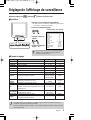
Monitoring display adjustment
7
English
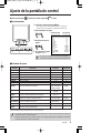
Adjustment method for : Composite/ : S-Video signal selection
■Operation
q Press the adjustment control (MENU).
r If necessary, repeat
steps w and e.
e Change the setting value.
w Choose the adjustment item.
POWERMODEAUTOMENU
MENU
qw e
Composite In NTSC
25
26
26
25
4
10
25
English
9300K
Full
Off
Pip Size
Normal
Color
Tint
Brightness
Contrast
Sharpness
Volume
H-Position
Language
Color Temp.
Scan
PIP
PIP SIZE/POS.
Display Mode
Recall
Setting valueAdjustment item
e At the top of the screen, an adjustment panel as shown in
the diagram to the right will be displayed.
Down Up
• Pressing the adjustment control (MENU) again, or waiting
for a number of seconds will cause the adjustment panel to
disappear.
■Adjustment item
Item Description Parameters Default setting
Color Adjust the color. 0 – 51 25
Tint Adjust the tint (only available for NTSC signal). 0 – 51 26
Brightness Adjust the brightness. 0 – 51 26
Contrast Adjust the contrast. 0 – 51 25
Sharpness Adjust the sharpness. 0 – 51 4
Volume Adjust the volume. 0 – 51 10
H-Position Adjust the horizontal position of the display. 0 – 51 25
English,
, ,
Language Select the language of the display. Français, Español, English
Deutsch, Italiano
Color Temp. Select the color temperature.
9300°K, 6500°K,
Standard
Standard
Scan Select the image scan type. Over, Under, Full, 1:1 Full
PIP
Select to use Picture in Picture, showing a sub window
VGA, DVI, Off Off
display in the upper left corner.
PIP SIZE/POS.
Changing the sub window display and display position. Pip Size, Pip Position,
–
Page 9) DEF. Hot Key
Display Mode The flickering of the screen is reduced. Normal, Interlace Normal
Recall
Pressing the +, – buttons together will return the
settings to the default setting.
––
* May differ depending on location of purchase.
• The settings will be retained even if the unit is switched off, but if the power supply is disconnected, settings
will return to default.
•
The default language display is English. If the language setting is changed, the menu display will be in the
language chosen.

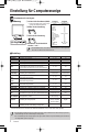
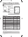
Computer display adjustment
8
English
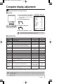
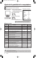
: Adjustment method for VGA signal selection
■Operation
Setting valueAdjustment item
POWERMODEAU TOMENU
MENU
VGA IN 1024x768@60Hz
Brightness
Contrast
H-Position
V-Position
Clock
Phase
Color Temp.
Use Color R
Use Color G
Use Color B
OSD H-Pos.
OSD V-Pos.
Volume
PIP
PIP SIZE/POS.
Language
Recall
26
25
25
32
25
8
User color
51
51
51
25
25
10
Off
DEF. Hot Key
English
q Press the adjustment control (MENU).
w Choose the adjustment item.
e Change the setting value.
r If necessary, repeat steps w and e.
Down Up
e At the top of the screen, an adjustment
panel as shown in the diagram to the right
will be displayed.
qw e
• Pressing the adjustment control (MENU) again, or waiting for a number of
seconds will cause the adjustment panel to disappear.
■Adjustment item
Item Description Parameters Default setting
Brightness Adjust the brightness. 0 – 51 26
Contrast Adjust the contrast. 0 – 51 25
H-Position* Adjust the horizontal position of the display. 0 – 51 25
V-Position* Adjust the vertical position of the display. 0 – 51 32
Adjust the clock (when vertical lines can be seen etc.).
Clock* •
Make fine adjustments until the vertical lines disappear. 0 – 51 25
Adjusting the clock will also change the width of the display.
Phase* Adjust the phase (when the screen is flickering, etc.). 0 – 51 8
Color Temp. Select the color temperature.
9300°K, 6500°K,
User color
User color
User Color R Adjust the Red (when Color temp. is set to User color). 0 – 51 51
User Color G Adjust the Green (when Color temp. is set to User color). 0 – 51 51
User Color B Adjust the Blue (when Color temp. is set to User color). 0 – 51 51
OSD H-Pos. Adjust the horizontal position of the adjustment panel. 0 – 51 25
OSD V-Pos. Adjust the vertical position of the adjustment panel. 0 – 51 25
Volume Adjust the volume. 0 – 51 10
PIP
Select to use Picture in Picture, showing a sub window Composite, S-Video,
Off
display in the upper left corner. Component, Off
PIP SIZE/POS.
Changing the sub window display and display position. Pip Size, Pip Position,
–
Page 9) DEF. Hot Key
English,
, ,
Language Select the language of the adjustment panel. Français, Español, English
Deutsch, Italiano
Recall
Pressing the +, – buttons together will return the
––
settings to the default value.
* Use this when pressing the automatic display adjustment control (AUTO) (page 6) does not achieve the desired result.
Also, by pressing the automatic display adjustment control (AUTO), these values will be changed.
• The settings will be retained even if the unit is switched off, but if the power supply is disconnected, settings
will return to default.
• The default language display is English. If the language setting is changed, the menu display will be in the
language chosen.

Computer display adjustment
9
English
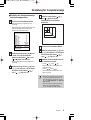
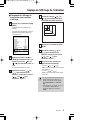
■Changing the sub window display
and display position
Press the adjustment control (MENU).
The menu window (Composite In) will be
displayed.
Once the menu window has been
displayed, it will disappear again if no
operations are carried out for approximately
10 seconds.
Press the [ ] or [ ] button to
select “PIP”, and then press the
[] or [ ] button to select
“VGA” or “DVI”.
The sub-window will be displayed on the
screen.
Press the [ ] or [ ] button to
select “PIP SIZE/POS.”, and then press
the [ ] or [ ] button to
select “Pip Size”.
3
2
Composite In NTSC
25
26
26
English
9300K
Full
Off
Pip Size
Normal
Color
Tint
Brightness
Language
Color Temp.
Scan
PIP
PIP SIZE/POS.
Display Mode
Recall
1
Press the [ ] or [ ] button
to change the size of the sub-window
(to one of three sizes).
Press the adjustment control (MENU).
Press the [ ] or [ ] button to
select “PIP SIZE/POS.”, and then press
the [ ] or [ ] button to
select “Pip Pos.”.
Use the following buttons to determine
the display position.
•[ ] and [ ] buttons:
Move the sub-window to the right and left.
•[ ] and [ ] buttons:
Move the sub-window up and down.
7
6
5
4
• The sound and luminance cannot be
adjusted while this setting is being made.
To make these other adjustments, set “PIP
SIZE/POS.” to “DEF. Hot Key”.
• To remove the sub-window, press the
adjustment control (MENU), select “PIP”
and then select “Off”.
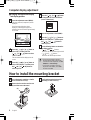
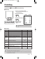
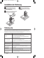
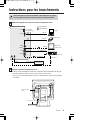
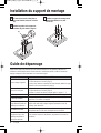
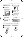
How to install the mounting bracket
Use a flat-tipped screwdriver or similar
tool to remove the cover (A).
Remove the four monitor stand screws
(B) and then remove the stand.
(B)
(A)
2
1
Install a wall mounting bracket (sold
separately) or other accessory.
3

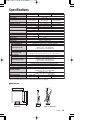
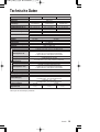
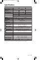
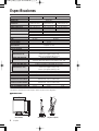
Specifications
10
English
Type
Color system
LCD display
Screen size
Viewable size (H x V)
Pixel pitch (H x V)
Power consumption
Weight (Adaptor included)
VMC-L1019/L1019P
19" active matrix
TFT LCD panel
480 mm diagonal
376 x 301 mm (5:4)
0.294 x 0.294 mm
VMC-L1017/L1017P
Color video monitor
NTSC, PAL
17" active matrix
TFT LCD panel
432 mm diagonal
337 x 270 mm (5:4)
0.264 x 0.264 mm
500 TV lines or more (Y/C input mode)
Horizontal: 30 K – 80 KH
Vertical: 56 Hz – 75 Hz
500:1
16.2 M
VESA compatible
VIDEO & S-VIDEO & VGA
Composite sync signal, 1.0 Vp-p, 75 Ω BNC connector
Separate Y/C signal, mini-DIN connector
Y signal: 1.0 Vp-p, 75 Ω negative sync
C signal: 0.286 Vp-p, 75 Ω negative sync
–6 dBs (400 mVrms), RCA pin
VGA Monitor Connector (15-pin)
Red signal, Green signal, Blue signal: 0.7 Vp-p, 75 Ω, positive sync
VMC-L1015/L1015P
15" active matrix
TFT LCD panel
381 mm diagonal
304 x 228 mm (4:3)
0.297 x 0.297 mm
1024 x 768
250 cd/m
2
5/11 ms
1280 x 1024
300 cd/m
2
Composite sync signal, 1.0 Vp-p, 75 Ω BNC connector
Separate Y/C signal, mini-DIN connector
Y signal: 1.0 Vp-p, 75 Ω negative sync
C signal: 0.286 Vp-p, 75 Ω negative sync
–6 dBs (400 mVrms), RCA pin
English/Chinese/French/German/Spanish/Italian/Japanese
Approx. 1 W
DC 12 V/4.16 A
Temperature: 0°C – 40°C
Humidity: 20% – 85% (non-condensation)
Temperature: –20°C – 60°C
Humidity: 20% – 85% (non-condensation)
5.0 kg
Approx. 50 W
Horizontal resolution
Scanning frequency
Contrast ratio
Brightness
Response time Tr/Tf
Display color
Display monitor timing
Display mode
Input connector
Video signal (BNC IN)
S-Video signal (Y/C IN)
Audio signal (AUDIO IN)
VGA signal (VGA IN)
Output connector
Video signal (BNC OUT)
S-Video signal (Y/C OUT)
Audio signal (AUDIO OUT)
Menu language
Audio power output
Power input
Operating condition
Storage condition
Approx. 40 W
4.0 kg
6.1 kg
Features and specifications are subject to change without prior notice or obligations.
2/6 ms
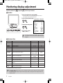
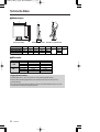
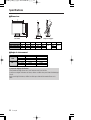
5˚
40˚
A
B
G
H
CD
F
E
(Angles of adjustment)
(Front view) (Side view)
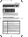
■ Dimensions

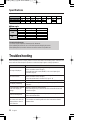
Troubleshooting
11
English
About the tilt adjustment
The screen may be adjusted 5° forward and 40° backward.
When adjusting the screen tilt, use a soft cloth to prevent damaging the screen.
After adjusting the tilt, check the cables to ensure the monitor is not pulled over.
VMC-L1015/L1015P
VMC-L1017/L1017P
VMC-L1019/L1019P
A
353.2
375
421.2
B
305.2
341
379.4
C
229.1
273.4
304
D
286
318
353.6
E
338
370
405.6
F
52
G
36.4
41.6
44.6
H
170
System
NTSC
PAL
Model Left/Right
70°/70°
75°/75°
75°/75°
70°/70°
75°/75°
75°/75°
Up/Down
60°/65°
70°/60°
70°/60°
60°/65°
70°/60°
70°/60°
■ View angle
VMC-L1015
VMC-L1017
VMC-L1019
VMC-L1015P
VMC-L1017P
VMC-L1019P
Model
Specifications
Before requesting service or repair, perform a check as described in the following section. If this does not
work, return the unit to the place of purchase or authorized repair agent to undergo adjustment.
Problem
No image is displayed.
• Is the connected device outputting a video signal?
• Is the connection correct? (Page 5)
• Using the input mode control (MODE), is the correct input signal
selected? (Page 6)
No sound is heard.
• Is the connected device outputting an audio signal?
• Is the connection correct? (Page 5)
• Check the volume level is not set to 0. (Page 6 – 8)
The display is dark. • Are the brightness and contrast set to the correct level? (Page 6 – 8)
The display is flickering.
• Is there a device nearby which is emitting a strong magnetic field? If so,
remove it.
Colors displayed in different
parts of the display are
strange.
• Is there a speaker or magnet nearby?
After removing the object, turn the unit off for at least 30 minutes and
switch it on again.
There is a hissing noise.
• Effects of this type may be caused by temperature changes in the room
but do not indicate a fault.
When 2 or more monitors
are next to each other, the
display shakes or there is
some distortion.
• The monitors are interfering with each other. Increase the distance
between them.
Points to check

BEDIENUNGSANLEITUNG
TFT-LCD-Farbmonitor
Deutsch
D
VMC-L1015/VMC-L1015P
VMC-L1017/VMC-L1017P
VMC-L1019/VMC-L1019P
Inhalt
Vorsichtsmassnahmen . . . . . . . . . . . . . . . . . . 1
Bezeichnung der Bedienungselemente und
der Teile. . . . . . . . . . . . . . . . . . . . . . . . . . . . . . 2
Anschlüsse . . . . . . . . . . . . . . . . . . . . . . . . . . . 4
Bedienung. . . . . . . . . . . . . . . . . . . . . . . . . . . . 5
Einstellung. . . . . . . . . . . . . . . . . . . . . . . . . . . . 6
Einstellung für Computeranzeige . . . . . . . . . . 7
Installation der Halterung. . . . . . . . . . . . . . . . . 9
Fehlersuche. . . . . . . . . . . . . . . . . . . . . . . . . . . 9
Technische Daten . . . . . . . . . . . . . . . . . . . . 10
Besonderheiten
• Mehrsprachige Menüs
Englisch/Chinesisch/Französisch/Deutsch/
Spanisch/Italienisch/Japanisch
• Bild-in-Bild-Funktion (PIP)
• Automatische NTSC/PAL-Umschaltung
• VESA Display Power Management Signaling
Über diese Anleitung
• In dieser Anleitung werden die Grundanschlüsse und Bedienungsanweisungen für die drei NTSC-Modelle
(VMC-L1015, L1017 und L1019) und die drei PAL-Modelle (VMC-L1015P, L1017P and L1019P) beschrieben.
Für nähere Informationen über die Modellvarianten wird auf die technischen Daten verwiesen.
• Lesen Sie bitte vor dem Installieren und dem Verwenden dieses Gerätes diese Bedienungsanleitung sorgfältig durch.
Bewahren Sie sie zum späteren Nachschlagen auf.

Vorsichtsmassnahmen
1
Deutsch
■ Nur die vorgeschriebene Stromquelle
verwenden.
■ Das Netzkabel aus der Steckdose ziehen,
wenn das Gerät für längere Zeit nicht
verwendet oder gereinigt wird.
■ Keine Gegenstände auf das Netzkabel
stellen. Das Gerät darf nicht so aufgestellt
werden, dass das Netzkabel mit Füssen
getreten wird. Die Steckdosen dürfen nicht
überlastet werden, weil dadurch ein Brand
oder ein elektrischer Schlag verursacht
werden kann.
■ Das Gerät darf nicht unter den folgende
Bedingungen verwendet werden:
- an extrem heißen, kalten oder feuchten
Orten,
- an staubigen Orten,
- in der Nähe von Geräten, die starke
Magnetfelder erzeugen,
- an Orten mit direkter Sonneneinstrahlung,
- an schlecht belüfteten Orten,
- in einem Auto bei geschlossenen Türen.
■ Die Belüftungsöffnungen dürfen nicht
abgedeckt werden, weil die Belüftung
beeinträchtigt wird.
■ Falls sich auf dem Bildschirm Staub
abgesetzt hat, muss dieser mit einem
weichen Tuch entfernt werden.
■ Ziehen Sie den Netzstecker aus der
Steckdose und wenden Sie sich unter den
folgenden Bedingungen an einen
qualifizierten Fachmann:
- bei beschädigtem oder ausgefranstem
Netzkabel,
- falls Flüssigkeiten in das Gerät eingedrungen
sind,
- falls das Gerät fallen gelassen wurde oder
das Gehäuse beschädigt ist,
- falls deutliche Leistungsänderungen auftreten.
■ Versuchen Sie niemals das Gerät selbst zu
warten, weil Sie sich beim Öffnen von
Abdeckungen gefährlichen Spannungen
und anderen Gefahren aussetzen können.
Reparaturen dürfen nur von qualifizierten
Fachleuten ausgeführt werden.
Bitte beachten:
Ihr SANYO Produkt wurde entworfen und
hergestellt mit qualitativ hochwertigen
Materialien und Komponenten, die recycelt und
wiederverwendet werden können.
Dieses Symbol bedeutet, daß elektrische und
elektronische Geräte am Ende ihrer
Nutzungsdauer von Hausmüll getrennt entsorgt
werden sollen.
Bitte entsorgen Sie dieses Gerät bei Ihrer
örtlichen kommunalen Sammelstelle oder im
Recycling Centre.
In der Europäischen Union gibt es
unterschiedliche Sammelsysteme für Elektrik-
und Elektronikgeräte.
Helfen Sie uns bitte, die Umwelt zu erhalten, in
der wir leben!
Dieses Symbol und das entsprechende
Recycling-System gelten nur für EU-Länder und
finden in den anderen Ländern der Welt keine
Anwendung.

Bezeichnung der Bedienungselemente und der Teile
2
Deutsch
Ansicht der Frontseite
MODE
AUTO
MENU
POWER
Bildschirm
q
w
e
r y
t
Einstelltaste (MENU)
Zur Feineinstellung (Seiten 6, 7)
Helligkeitsregler
Einstellung der Bildschirmhelligkeit. (Seite 5)
• Auswahl des entsprechenden Menüpunktes.
Kontrastregler
Zur Einstellung des Kontrasts. (Seite 5)
• Auswahl des entsprechenden Menüpunktes.
Lautstärkeregler
Einstellung des Lautstärkepegels. (Seite 5)
• Für die Einstellung bzw. Änderung des
Einstellwerts.
Automatische Bildschirmeinstelltaste (AUTO)
Automatische Einstellung der Bildschirmanzeige
(für VGA-Anschluss) (Seite 5)
Eingangsbetriebsarttaste (MODE)
Zum Umschalten der Betriebsart. (Seite 5)
Netztaste (POWER)
Zum Ein- und Ausschalten der Stromversorgung.
w
e
q
r
t
y
Netzanzeige
Falls an den folgenden Eingangsbuchsen kein
Signal anliegt, wird der Monitor automatisch in
die Energiesparbetriebsart umgeschaltet.
Es wird auf einen blauen Bildschirm
umgeschaltet (die Anzeige “Power Saving”
erscheint für ungefähr 10 Sekunden) und danach
wird auf einen schwarzen Bildschirm
umgeschaltet.
Drücken Sie zum Aufheben der
Energiesparbetriebsart die Netztaste (POWER)
zweimal. Es wird auf einen blauen Bildschirm
umgeschaltet und die Anzeige “No signal”
erscheint, schließen Sie eine Signalquelle an den
Buchsen an.
(Rückseite)
• Eingangsbuchse für Composite-Signal
(BNC IN)
• S-Videoeingangsbuchse (Y/C IN)
• VGA-Eingangsbuchse (VGA IN)
■Zubehör
• Netzgerät/Netzkabel
• VGA-Anschlusskabel
■Energiesparbetriebsart

Bezeichnung der Bedienungselemente und der Teile
3
Deutsch
Ansicht der Rückseite
BNC IN
DC IN
VGA IN
BNC OUT
Y/C IN
Y/C OUT
AUDIO OUT AUDIO IN
VGA-Eingangsbuchse (VGA IN)
Für den Eingang eines VGA-
Computersignals (Video Graphics Array).
S-Videoeingangsbuchse (Y/C IN)
Für den Eingang von S-Videosignalen.
Audioeingangsbuchse
(AUDIO IN)
Für Toneingang
S-Videoausgangsbuchse (Y/C OUT)
Für den Ausgang von S-Videosignalen.
Audioausgangsbuchse
(AUDIO OUT)
Für Tonausgang
Gleichstrombuchse (DC IN) (Seite 4)
Eingangsbuchse für Composite-Signal
(BNC IN)
Für den Eingang eines Signals von einer
CCD-Überwachungskamera.
Ausgangsbuchse für Composite-Signal
(BNC OUT)
Übertragung der Bildsignale von der
Buchse BNC IN.
■VGA-Eingangsbuchse
Signal
Rotsignal
Grünsignal
Blausignal
Nicht verwendet
Nicht verwendet
Masse (rot)
Masse (grün)
Masse (blau)
Nicht verwendet
Masse (Synchro)
Nicht verwendet
SDA
H-Synchronisierung
V-Synchronisierung
SCL
q
w
e
r
t
y
u
i
o
!0
!1
!2
!3
!4
!5
Klemme
qet
!5 !4 !3 !2 !1
!0 oiuy
rw
■S-Videosignalbuchse
OUT
IN
w
r
w
r
q
e
q
e
Klemme
q
w
e
r
Signal
Masse (Y)
Masse (C)
Y
C

Anschlüsse
4
Deutsch
• Für den Anschluss müssen alle Geräte ausgeschaltet sein.
• Andere Geräte und die Anschlusskabel sind separat erhältlich.
BNC IN
DC IN
VGA IN
BNC OUT
Y/C IN
Y/C OUT
AUDIO OUT AUDIO IN
Monitor-Fernseher
usw.
Festplattenrecorder usw.
AUDIO LINE IN
VGA OUT
BNC OUT
Y/C (S-VIDEO) OUT
Y/C (S-VIDEO) IN
AUDIO LINE OUT
BNC IN
CCD-Kamera usw.
(mitgeliefertes VGA-Anschlusskabel)
Computer
: Eingangssignal
: Ausgangssignal
Verstärker usw.
Anschlussbeispiel
(Für die Anweisung wird
auf x verwiesen.)
Schließen Sie die Geräte an den rückseitigen Buchsen an.
1
Netzgerät
(mitgeliefert)
Netzkabel (mitgeliefert)
Schließen Sie das Gleichstromkabel (DC 12V) an.
2
Schließen Sie den Netzgerätestecker an der Gleichstrombuchse (DC IN) an und verbinden Sie das
Netzgerät mit dem Netzkabel an einer Steckdose.
• Nach dem Anschließen ist die Stromversorgung hergestellt.

Bedienung
5
Deutsch
POWERMODEAUTOMENU
1 5
2
43
2
A
B
Drücken Sie die Netztaste (POWER) zum
Einschalten.
e Die Netzanzeige leuchtet.
Stellen Sie das Eingangssignal mit der
Eingangsbetriebsarttaste (MODE) ein.
• Bei einmaligem Drücken wird das
gegenwärtig eingestellte Signal
angezeigt. Bei nochmaligem Drücken
werden die möglichen Signaloptionen in
der nachstehenden Reihenfolge
angezeigt. (Das Symbol für die gewählte
Option wird in der oberen linken
Bildschirmecke eingeblendet.)
: VGA-Signal (VGA IN)
: DVI-Signal (DVI IN)
Optional
: Composite-Signal (BNC IN)
: S-Videosignal (Y/C IN)
: Component Signal (Y, Cb, Cr IN)
Kann nicht verwendet werden.
MODE
2
POWER
Netzanzeige
1
•
Beim Umschalten des Signals erscheint zuerst
ein blauer Bildschirm und nach 2 bis 3 Sekunden
wird das eingestellte Signal angezeigt.
•
Falls am eingestellten Signaleingang kein Signal
anliegt, erscheint die Anzeige “No signal”.
•
Falls das angeschlossenen Gerät ausgeschaltet
ist, erscheint die Anzeige “Video Loss”.
Stellen Sie die Helligkeit ein ( ) [0 – 51].
• Während der Einstellung der Helligkeit
wird in der oberen linken Bildschirmecke
das Symbol eingeblendet.
Stellen Sie den Kontrast ein ( ) [0 – 51].
• Während der Einstellung des Kontrasts
wird in der oberen linken Bildschirmecke
das Symbol eingeblendet.
Stellen Sie den Lautstärkepegel ein [0 – 51].
• Während der Einstellung des
Lautstärkepegels wird in der oberen
linken Bildschirmecke das Symbol
eingeblendet.
Automatische Bildschirmeinstellung
(für VGA-Signal)
e
Der Takt, die Phase und die Bildschirm-
position werden automatisch,
entsprechend dem anliegenden
Eingangssignal eingestellt.
Drücken Sie am Ende die Netztaste (POWER).
e Die Netzanzeige erlischt.
5
AUTO
B
Verringern Erhöhen
A
Verringern Erhöhen
4
Verringern Erhöhen
3

Einstellung
6
Deutsch
Einstellmethode für : Composite/ : S-Videosignaleinstellung
■Bedienung
q Drücken Sie die Einstelltaste (MENU).
r Wiederholen Sie bei
Bedarf die Schritte
w und e.
e Ändern Sie die Einstellung.
w Wählen Sie die Einstellung.
POWERMODEAUTOMENU
MENU
qw e
Composite In NTSC
25
26
26
25
4
10
25
Deutsch
9300K
Voll
Aus
Pip Size
Normal
EinstellwertEinstellung
Farbe
Farbton
Helligkeit
Kontrast
Schärfe
Volumen
H-Position
Sprache
Farb Temp
Scannen
PIP
PIP SIZE/POS.
Display Mode
Zurücksetzen
e Oben auf dem Bildschirm wird das rechts gezeigte
Einstellfeld eingeblendet.
Ab Auf
• Das Einstellfeld erlischt, wenn die Einstelltaste (MENU)
nochmals gedrückt wird oder nach Ablauf einer bestimmten
Zeit.
■Einstellung
Punkt Beschreibung Parameter Voreinstellung
Farbe Einstellung der Farbe. 0 – 51 25
Farbton Einstellung des Farbtons (nur für NTSC-Signale). 0 – 51 26
Helligkeit Einstellung der Helligkeit. 0 – 51 26
Kontrast Einstellung des Kontrasts. 0 – 51 25
Schärfe Einstellung der Bildschärfe. 0 – 51 4
Volumen Einstellung des Lautstärkepegels. 0 – 51 10
H-Position Einstellung der horizontalen Position der Anzeige. 0 – 51 25
English,
, ,
Sprache Einstellung der Anzeigesprache. Français, Español, English
Deutsch, Italiano
Farb Temp Einstellung der Farbtemperatur.
9300°K, 6500°K,
Standard
Standard
Scannen Einstellung der Bildabtastung. Über, Unter, Voll, 1:1 Voll
PIP
Einstellung der Bild-in-Bild-Funktion, Einblendung einer
zusätzlichen Anzeige in der oberen linken Bildschirmecke.
VGA, DVI, Aus Aus
PIP SIZE/POS.
Einstellen der Unterfensteranzeige und der Pip Size, Pip Position,
–
Anzeigeposition. Seite 8) DEF. Hot Key
Display Mode Das Flimmern des Bildschirms vermindert sich. Normal, Interlace Normal
Zurücksetzen
Bei gleichzeitigen Drücken der Tasten + und – wird die
Einstellung auf die Voreinstellung zurückgestellt.
––
* Kann je nach Land verschieden sein.
• Die Einstellungen bleiben beim Ausschalten gespeichert, beim Unterbrechen der Stromversorgung werden
die Einstellungen auf die Voreinstellungen zurückgestellt.
•
Die Voreinstellung für die Anzeigesprache ist Englisch. Beim Ändern der Spracheinstellung wird das Menü in
der eingestellten Sprache angezeigt.

Einstellung für Computeranzeige
7
Deutsch
: Einstellmethode für VGA-Signale
EinstellwertEinstellung
POWERMODEAU TOMENU
MENU
VGA IN 1024x768@60Hz
Helligkeit
Kontrast
H-Position
V-Position
Uhr
Phase
Farb Temp
Einstellung Rot
Einstellung Grün
Einstellung Blau
OSD H-POS
OSD V-POS
Volumen
PIP
PIP SIZE/POS.
Sprache
Zurücksetzen
26
25
25
32
25
8
Einstel Farbe
51
51
51
25
25
10
Aus
DEF. Hot Key
Deutsch
q
Drücken Sie die Einstelltaste (MENU).
w Wählen Sie die Einstellung.
e Ändern Sie die Einstellung.
r Wiederholen Sie bei Bedarf die
Schritte w und e.
Ab Auf
e
Oben auf dem Bildschirm wird das rechts
gezeigte Einstellfeld eingeblendet.
qw e
■Bedienung
• Das Einstellfeld erlischt, wenn die Einstelltaste (MENU) nochmals gedrückt
wird oder nach Ablauf einer bestimmten Zeit.
■Einstellung
Punkt Beschreibung Parameter Voreinstellung
Helligkeit Einstellung der Helligkeit. 0 – 51 26
Kontrast Einstellung des Kontrasts. 0 – 51 25
H-Position* Einstellung der horizontalen Position der Anzeige. 0 – 51 25
V-Position* Einstellung der vertikalen Position der Anzeige. 0 – 51 32
Einstellung des Taktes (wenn vertikale Linien sichtbar sind).
Uhr* • Feineinstellung bis die vertikalen Linien verschwinden. 0 – 51 25
Beim Einstellen des Taktes ändert sich auch die Anzeigebreite.
Phase* Einstellung der Phase (bei flimmernder Anzeige). 0 – 51 8
Farb Temp Einstellung der Farbtemperatur.
9300°K, 6500°K,
Einstel Farbe
Einstel Farbe
Einstellung Einstellung von Rot (falls die Farbtemperatur auf einen
Rot Benutzerwert eingestellt ist).
0 – 51 51
Einstellung Einstellung von Grün (falls die Farbtemperatur auf einen
Grün Benutzerwert eingestellt ist).
0 – 51 51
Einstellung Einstellung von Blau (falls die Farbtemperatur auf einen
Blau Benutzerwert eingestellt ist). 0 – 51 51
OSD H-POS Einstellung der horizontalen Position des Anzeigefelds. 0 – 51 25
OSD V-POS Einstellung der vertikalen Position des Anzeigefelds. 0 – 51 25
Volumen Einstellung des Lautstärkepegels. 0 – 51 10
PIP
Einstellung der Bild-in-Bild-Funktion, Einblendung einer
Composite, S-Video,
Aus
zusätzlichen Anzeige in der oberen linken Bildschirmecke.
Komponente, Aus
PIP SIZE/POS.
Einstellen der Unterfensteranzeige und der Pip Size, Pip Position,
–
Anzeigeposition. Seite 8) DEF. Hot Key
English,
, ,
Sprache Einstellung der Anzeigesprache. Français, Español, English
Deutsch, Italiano
Zurücksetzen
Bei gleichzeitigen Drücken der Tasten + und – wird die
––
Einstellung auf die Voreinstellung zurückgestellt.
* Verwendung, wenn mit der automatischen Bildschirmeinstellung (AUTO) (Seite 5) das gewünschte Resultat nicht
erzielt wird. Bei Drücken der automatischen Bildschirmeinstelltaste (AUTO) werden diese Werte geändert.
• Die Einstellungen bleiben beim Ausschalten gespeichert, beim Unterbrechen der Stromversorgung werden
die Einstellungen auf die Voreinstellungen zurückgestellt.
•
Die Voreinstellung für die Anzeigesprache ist Englisch. Beim Ändern der Spracheinstellung wird das Menü in
der eingestellten Sprache angezeigt.
Seite laden ...
Seite laden ...
Seite laden ...
Seite laden ...
Seite laden ...
Seite laden ...
Seite laden ...
Seite laden ...
Seite laden ...
Seite laden ...
Seite laden ...
Seite laden ...
Seite laden ...
Seite laden ...
Seite laden ...
Seite laden ...
Seite laden ...
Seite laden ...
Seite laden ...
Seite laden ...
Seite laden ...
Seite laden ...
Seite laden ...
Seite laden ...
Seite laden ...
Seite laden ...
Seite laden ...
Seite laden ...
-
 1
1
-
 2
2
-
 3
3
-
 4
4
-
 5
5
-
 6
6
-
 7
7
-
 8
8
-
 9
9
-
 10
10
-
 11
11
-
 12
12
-
 13
13
-
 14
14
-
 15
15
-
 16
16
-
 17
17
-
 18
18
-
 19
19
-
 20
20
-
 21
21
-
 22
22
-
 23
23
-
 24
24
-
 25
25
-
 26
26
-
 27
27
-
 28
28
-
 29
29
-
 30
30
-
 31
31
-
 32
32
-
 33
33
-
 34
34
-
 35
35
-
 36
36
-
 37
37
-
 38
38
-
 39
39
-
 40
40
-
 41
41
-
 42
42
-
 43
43
-
 44
44
-
 45
45
-
 46
46
-
 47
47
-
 48
48


Sanyo VMC-L1019P Benutzerhandbuch
- Typ
- Benutzerhandbuch
- Dieses Handbuch ist auch geeignet für
in anderen Sprachen
- English: Sanyo VMC-L1019P User manual
- français: Sanyo VMC-L1019P Manuel utilisateur
- español: Sanyo VMC-L1019P Manual de usuario
Verwandte Papiere
Sonstige Unterlagen
-
Eneo VMC-19LCD-HPPG1 Installation And Operating Instructions Manual
-
-
-
-
-
-
-
Philips 14-COLOR MONITOR-RECEIVER 14RF50S Bedienungsanleitung
-
Samsung SMT-3211N Benutzerhandbuch
-