Bresser XXL Weather Center JC Bedienungsanleitung
- Typ
- Bedienungsanleitung

Wetterstation · Weather Station ·
XXL Weather Center JC
DE Schnellstartanleitung
EN Quickstart guide

DE
Besuchen Sie unsere Website über den folgenden QR Code oder Weblink um weitere Informationen
zu diesem Produkt oder die verfügbaren Übersetzungen dieser Anleitung zu finden.
EN
Visit our website via the following QR Code or web link to find further information on this product or
the available translations of these instructions.
FR
Si vous souhaitez obtenir plus d’informations concernant ce produit ou rechercher ce mode
d’emploi en d’autres langues, rendez-vous sur notre site Internet en utilisant le code QR ou le lien
correspondant.
NL
Bezoek onze internetpagina via de volgende QR-code of weblink, voor meer informatie over dit
product of de beschikbare vertalingen van deze gebruiksaanwijzing.
ES
¿Desearía recibir unas instrucciones de uso completas sobre este producto en un idioma determinado?
Entonces visite nuestra página web utilizando el siguiente enlace (código QR) para ver las versioneAs
disponibles.
IT
Desidera ricevere informazioni esaustive su questo prodotto in una lingua specifica? Venga a
visitare il nostro sito Web al seguente link (codice QR Code) per conoscere le versioni disponibili.
www.bresser.de/P7002590
www.bresser.de/warranty_terms
GARANTIE · WARRANTY · GARANTÍA · GARANZIA

Deutsch .................................................................................................................
4
English...................................................................................................................
12

4 / 20
1 Impressum
Bresser GmbH
Gutenbergstr. 2
46414 Rhede
Germany
http://www.bresser.de
Für etwaige Gewährleistungsansprüche oder Serviceanfragen verweisen wir auf die Informationen zu
„Garantie“ und „Service“ in dieser Dokumentation. Wir bitten um Verständnis, dass direkt an die Her-
steller-Anschrift gerichtete Anfragen oder Einsendungen nicht bearbeitet werden können.
Irrtümer und technische Änderungen vorbehalten.
© 2018 Bresser GmbH
Alle Rechte vorbehalten.
Die Reproduktion dieser Dokumentation – auch auszugsweise – in irgendeiner Form (z.B. Fotokopie,
Druck, etc.) sowie die Verwendung und Verbreitung mittels elektronischer Systeme (z.B. Bilddatei,
Website, etc.) ohne eine vorherige schriftliche Genehmigung des Herstellers ist nicht gestattet.
Die in dieser Dokumentation verwendeten Bezeichnungen und Markennamen der jeweiligen Firmen
sind im Allgemeinen in Deutschland, der Europäischen Union und/oder weiteren Ländern waren-, mar-
ken- und/oder patentrechtlich geschützt.
2 Gültigkeitshinweis
Diese Dokumentation ist gültig für die Produkte mit den nachfolgend aufgeführten Artikelnummern:
7002590
Anleitungsversion: v1118
Bezeichnung dieser Anleitung:
Quickstart_7002590_XXL-Weather-Center-JC_de-en_BRESSER_v112018a
Informationen bei Serviceanfragen stets angeben.
3 Zu dieser Anleitung
HINWEIS
Diese Schnellstart-Anleitung ersetzt nicht die ausführliche Bedienungsanleitung!
Lesen Sie vor Benutzung des Geräts aufmerksam die Sicherheitshinweise und die ausführliche Bedie-
nungsanleitung.

5 / 20
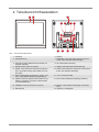
4 Teileübersicht Basisstation
11
15
1
6
2
3
7
5
4
8
12
14
16
17
18
13
10
9
Abb.1: Alle Teile der Basisstation
1 Gehäuse 2 Display
3 Wandhalterung 4 MAX/MIN-Taste (Wechsel zwischen Höchst-,
Tiefst- oder aktueller Werteanzeige)
5 HISTORY-Taste (Messwerte der letzten 24
Stunden abrufen)
6 UP-Taste (Wert erhöhen)
7 DOWN-Taste (Wert verringern) 8 TIME-Taste (Manuelle Zeiteinstellung)
9 BARO-Taste (Wechsel zwischen Anzeige in
hPa, InHg oder mmHg sowie Wahl der Luft-
druckart)
10 WIND-Taste (Wechsel zwischen durchschnitt-
licher und aktueller Windböe)
11 RAIN-Taste (Wechsel zwischen Tages-, Wo-
chen- oder Monats-Niederschlagsmenge)
12 °C/°F Schiebeschalter
13 INDEX-Taste (Anzeigewechsel zwischen ge-
fühlter Temperatur, Taupunkt, Wärmeindex
und Windkühlfaktor)
14 RCC-Taste (Zeitsignal-Empfang initiieren)
15 SENSOR-Taste (Funksensor suchen) 16 RESET-Taste (alle Einstellungen zurückset-
zen)
17 Batteriefach 18 Standfuß, ausklappbar

6 / 20
5 Teileübersicht Multisensor
1
3
4
5
6
9
8
7
13
10
12
11
E
D
F
G
7
8
12
2
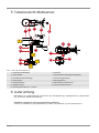
Abb.2: Alle Teile des Multisensors
1 Regensammelbehälter 2 Antenne
3 Dosenlibelle 4 Windschalen (Windgeschwindigkeit)
5 Windfahne (Windrichtung) 6 Thermo-/Hygrometer
7 Rohrschelle 8 Montageschuh
9 Montagestange 10 Batteriefach(-abdeckung)
11 RESET-Knopf 12 LED-Funktionsleuchte
13 Montageschrauben mit -muttern
6 Lieferumfang
Basisstation (A), multifunktionaler Außensensor (D), Montagestab (E), Montageschuh (F), Rohrschelle
(G), Schrauben, Bedienungsanleitung
Außerdem erforderlich (nicht im Lieferumfang enthalten):
4 Stück 1.5V Batterien Typ AA (Basisstation), 3 Stück 1.5V Batterien Typ AA (Außensensor)

7 / 20
7 Display-Anzeigen
12
10
11
8
19
1
18
17
16
14
15
9
6
5
4
3
7
2
13
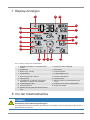
Abb.3: Display-Anzeigen für die Basisstation
1 AM/PM-Information im 12-Stunden-Zeit-
modus
2 Symbol für das Funksignal
3 Mondphase 4 Wochentag
5 Datum (Tag - Monat) 6 Innentemperatur
7 Klimaindikator 8 Luftfeuchtigkeit innen
9 Niederschlag oder Luftdruck 10 Windgeschwindigkeit
11 Windrichtung 12 Wind-Indikator
13 Informationen zu gefühlter Temperatur,
Windkühle, Taupunkt und Hitzeindex
14 Beaufort-Skala zur Windstärkeneinord-
nung
15 Luftfeuchtigkeit außen 16 Indikator für die Sensor-Signalstärke
17 Außentemperatur 18 Wettervorhersage
19 Aktuelle Uhrzeit (Stunden:Minuten:Sekun-
den)
8 Vor der Inbetriebnahme
HINWEIS
Vermeidung von Verbindungsstörungen!
Um Verbindungsstörungen zwischen den Geräten zu vermeiden, sind die folgenden Punkte bei der In-
betriebnahme zu beachten.

8 / 20
1. Basisgerät (Empfänger) und Sensor (Sender) so nah wie möglich nebeneinander stellen/legen.
2. Stromversorgung für das Basisgerät herstellen und ca. 5 Sekunden warten.
3. Stromversorgung für den Sensor herstellen.
4. Basisgerät und Sensor innerhalb des effektiven Übertragungsbereichs aufstellen/betreiben.
Bei einem Batteriewechsel stets alle Batterien entfernen und in richtiger Reihenfolge wieder neu ein-
setzen, damit die Funkverbindung erneut aufgebaut werden kann. Wird eines der beiden Geräte über
einen Netzstromanschluss betrieben, so muss auch für dieses bei einem Batteriewechsel kurzzeitig
die Stromverbindung getrennt werden. Werden z.B. nur die Batterien im Sensor ausgetauscht, kann
das Signal anschließend gar nicht oder nicht mehr korrekt empfangen werden.
Beachten Sie, dass die tatsächliche Reichweite von den jeweils verwendeten Baumaterialien der Ge-
bäude sowie der jeweiligen Position der Basiseinheit und des Außensensors abhängt. Durch externe
Einflüsse (diverse Funksender und andere Störquellen) kann die mögliche Distanz stark reduzieren. In
solchen Fällen empfehlen wir, sowohl für das Basisgerät als auch den Außensensor andere Standorte
zu suchen. Manchmal reicht schon ein Verschieben um wenige Zentimeter! Obwohl der Außensensor
wetterfest ist, sollte er nicht an Orten mit Einfall von direkter Sonneneinstrahlung, Regen oder Schnee
platziert werden.
9 Stromversorgung herstellen
Basisgerät
1. Batteriefachdeckel entfernen.
2. Batterien in das Batteriefach einsetzen. Dabei die korrekte Ausrichtung der Batteriepole (+/-) be-
achten.
3. Batteriefachdeckel wieder aufsetzen.
Funksensor
4. Schraube am Batteriefachdeckel mit einem geeigneten Kreuzschraubendreher entfernen und Bat-
teriefachdeckel abnehmen.
5. Batterien in das Batteriefach einsetzen. Dabei die korrekte Ausrichtung der Batteriepole (+/-) be-
achten.
6. Batteriefachdeckel wieder aufsetzen und anschrauben.
10 Multifunktions-Funksensor montieren und
anbringen
Abhängig vom gewünschten Standort kann der Funksensor auf verschiedene Weise montiert werden.
HINWEIS!Bei der Montage stets darauf achten, dass sich der obere Teile der Windfahne min-
destens 1,5 Meter über dem Erdboden befindet. Beim Anbringen mithilfe der Dosenlibelle im
Sensorkopf für eine absolut waagerechte Position sorgen. Das Windrad muss stets nach Norden
zeigen.
Montage an einem vertikal oder horizontal ausgerichteten Holzelement
1. Ein Ende des Montagestabes in die Öffnung unterhalb des Sensorkopfes stecken.
2. Eine Schraube durch die Bohrung schieben und auf der anderen Seite die Mutter aufsetzen. Die
Schraubverbindung handfest anziehen.
3. Je nach gewünschter Ausrichtung das andere Ende des Montagestabes in die Öffnung des Mon-
tagefußes für eine horizontale oder für eine horizontale Montage stecken.
4. Eine weitere Schraube die Bohrung des Montagefußes schieben und auf der anderen Seite die
Mutter aufsetzen. Die Schraubverbindung handfest anziehen.
5. Die Unterseite des Montagefußes auf das Holzelement setzen und mit 4 geeigneten Holzschrau-
ben anschrauben.

9 / 20
Montage an einem vertikal oder horizontal ausgerichteten Rohr
6. Die Schritte 1 bis 4 wie zuvor ausführen.
7. Die Unterseite des Montagefußes auf das Rohr aufsetzen und die Rohrschelle von der anderen
Seite gegen das Rohr drücken.
8. Die 4 Schrauben durch die Bohrungen des Montagefußes und auf der anderen Seite durch die
Bohrungen der Rohrschelle stecken.
9. Die 4 Muttern aufsetzen und die Schraubverbindungen handfest anziehen.
11 Signalübertragung
Die Basisstation verbindet sich automatisch mit dem Außensensor. SENSOR-Taste drücken, um ma-
nuell nach den Sensor zu suchen. Bei erfolgreicher Verbindung wird der Indikator für die Sensor-Si-
gnalstärke auf dem Display angezeigt.
Verbindungsstatus-Anzeige:
Verbindungsstatus Displayanzeige
Gutes Signal Empfangssymbol
Sensor wird gesucht Empfangssymbol blinkt
Kein Signal seit 48 Stunden ‚Er‘ (Error) wird angezeigt
Sensor Batteriestand niedrig, gutes Signal Batterie-Symbol wird angezeigt
12 Automatische Zeiteinstellung
Nachdem die Stromversorgung hergestellt wurde, sucht das Gerät automatisch nach dem Funksignal.
Es dauert etwa 3-8 Minuten bis dieser Prozess abgeschlossen ist.
Bei korrektem Empfang des Funksignals werden Datum und Uhrzeit automatisch eingestellt und das
Empfangssymbol wird angezeigt.
Wird kein Funksignal empfangen, folgendermaßen vorgehen:
1. RCC-Taste am Basisgerät drücken bis das Symbol für das Funksignal blinkt.
2. Wird weiterhin kein Funksignal empfangen, muss die Zeiteinstellung manuell vorgenommen wer-
den.
Nähere Informationen zur manuellen Zeit- und Weckrufeinstellung sind der ausführlichen Bedienungs-
anleitung zu entnehmen (siehe Download-Information auf Seite 2).
13 Automatische Messwerteübertragung
Sobald die Batterien eingelegt wurden, beginnt die Basisstation mit der Anzeige der Messwerte für
den Innenbereich. Die ersten vom Außensensor empfangenen Messwerte werden innerhalb von etwa
3 Minuten nach Inbetriebnahme angezeigt.
Nähere Informationen zum Abruf weiterer Messwerte sind der ausführlichen Bedienungsanleitung zu
entnehmen (siehe Download-Information auf Seite 2).
14 EG-Konformitätserklärung
Hiermit erklärt Bresser GmbH, dass der Funkanlagentyp mit Artikelnummer 7002590 der Richtlinie
2014/53/EU entspricht. Der vollständige Text der EG-Konformitätserklärung ist unter der folgenden
Internetadresse verfügbar: www.bresser.de/download/7002590/CE/7002590_CE.pdf

10 / 20
15 Reinigung und Wartung
• Trennen Sie das Gerät vor der Reinigung von der Stromquelle (Netzstecker ziehen oder Batterien
entfernen)!
• Reinigen Sie das Gerät nur äußerlich mit einem trockenen Tuch. Benutzen Sie keine Reinigungs-
flüssigkeit, um Schäden an der Elektronik zu vermeiden.
Regen-Auffangbehälter (Trichter) reinigen
1. Drehen Sie den Auffangbehälter um etwa 30° gegen den Uhrzeigersinn.
2. Ziehen Sie den Trichter vorsichtig nach oben heraus.
3. Reinigen Sie ihn und entfernen Sie Schmutz und Insekten.
4. Setzen Sie den Trichter wieder ein, wenn er vollständig gereinigt und trocken ist.
Thermo/Hygro-Sensor reinigen
5. Drehen Sie die beiden Schrauben unterhalb des Sensors mit einem kleinen Kreuzschraubendre-
her heraus.
6. Ziehen Sie den Lamellenaufsatz vorsichtig nach unten ab.
7. Entfernen Sie vorsichtig Schmutz und Insekten aus dem Sensorgehäuse.
Hinweis
Der Lamellenaufsatz besteht aus einzelnen ineinander gesteckten Elementen. Die beiden untersten
sind geschlossen. Ändern Sie nicht die Reihenfolge! Der Sensor im Inneren des Gehäuses darf nicht
mit Wasser in Berührung kommen!
• Reinigen Sie die Lamellen und entfernen Sie Schmutz und Insekten.
• Bringen Sie den Lamellenaufsatz wieder an, wenn er vollständig gereinigt und trocken ist.
16 Entsorgung
Entsorgen Sie die Verpackungsmaterialien sortenrein. Informationen zur ordnungsgemäßen
Entsorgung erhalten Sie beim kommunalen Entsorgungsdienstleister oder Umweltamt.
Werfen Sie Elektrogeräte nicht in den Hausmüll!
Gemäß der Europäischen Richtlinie 2012/19/EG über Elektro- und Elektronik-Altgeräte und
deren Umsetzung in nationales Recht müssen verbrauchte Elektrogeräte getrennt gesam-
melt und einer umweltgerechten Wiederverwertung zugeführt werden.

11 / 20
Batterien und Akkus dürfen nicht im Hausmüll entsorgt werden. Sie sind zur Rückgabe ge-
brauchter Batterien und Akkus gesetzlich verpflichtet und können die Batterien nach Ge-
brauch entweder in unserer Verkaufsstelle oder in unmittelbarer Nähe (z.B. im Handel oder in
kommunalen Sammelstellen) unentgeltlich zurückgeben.
Batterien und Akkus sind mit einer durchgekreuzten Mülltonne sowie dem chemischen Sym-
bol des Schadstoffes bezeichnet, "Cd" steht für Cadmium, "Hg" steht für Quecksilber und "Pb"
steht für Blei.
17 Garantie
Die reguläre Garantiezeit beträgt 2 Jahre und beginnt am Tag des Kaufs. Um von einer verlängerten,
freiwilligen Garantiezeit wie auf dem Geschenkkarton angegeben zu profitieren, ist eine Registrierung
auf unserer Website erforderlich.
Die vollständigen Garantiebedingungen sowie Informationen zu Garantiezeitverlängerung und Ser-
viceleistungen können Sie unter www.bresser.de/garantiebedingungen einsehen.

12 / 20
1 Imprint
Bresser GmbH
Gutenbergstr. 2
46414 Rhede
Germany
http://www.bresser.de
If you wish to submit a warranty claim or service request, please refer to the “Warranty” and “Service”
information in this document. Please be aware that any requests or submissions sent directly to the
manufacturer cannot be processed.
Errors excepted. Subject to technical modifications.
© 2018 Bresser GmbH
All rights reserved.
Reproduction of this document, including extracts, in any form (photocopied, printed etc.) or the use
and distribution of this document by electronic means (image file, website etc.) is not permitted without
the prior written consent of the manufacturer.
The terms and brand names of the respective companies used in this document are protected by
brand, patent or product law in Germany, the European Union and/or other countries.
2 Validity information
This documentation is valid for the products with the article numbers listed below:
7002590
Manual version: v1118
Manual description:
Quickstart_7002590_XXL-Weather-Center-JC_de-en_BRESSER_v112018a
With any service inquiries, please state these information.
3 About this Instruction Manual
NOTICE
This Quick Start guide is not intended to replace the more detailed user manual.
Please read the safety instructions and the operating instructions carefully before use.

13 / 20
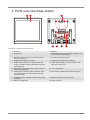
4 Parts overview Base station
11
15
1
6
2
3
7
5
4
8
12
14
16
17
18
13
10
9
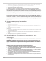
Illustration1: All parts of the base station
1 Housing 2 Display
3 Wall mount 4 MAX/MIN button (switch between highest, low-
est or current value display)
5 HISTORY button (retrieve measurements for
the past 24 hours)
6 UP button (increase value)
7 DOWN button (decrease value) 8 TIME button (manual time setting)
9 BARO button (display change between hPa,
InHg or mmHG as well as barometric pressure
type selection)
10 WIND button (display change between aver-
age and current gust)
11 RAIN button (change between daily, weekly or
monthly precipitation)
12 °C/°F slide switch
13 INDEX button (display change between 'feels
like' temperature, dew point, heat index and
wind chill index)
14 RCC button (initialize time signal reception)
15 SENSOR button (initialize remote sensor data
reception)
16 RESET button (reset all settings)
17 Battery compartment 18 Stand, fold-out

14 / 20
5 Parts overview Multisensor
1
3
4
5
6
9
8
7
13
10
12
11
E
D
F
G
7
8
12
2
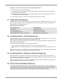
Illustration2: All parts of the multisensor
1 Rain gauge 2 Antenna
3 Circular level 4 Wind cups (wind speed)
5 wind vane (wind direction) 6 Thermo-Hygrometer
7 Pipe clamp 8 Mounting shoe
9 Mounting bar 10 Battery compartment (cover)
11 RESET button 12 LED function indicator
13 Mounting screws with nuts
6 Scope of delivery
Base station (A), power adapter (B), stand (C), multifunctional outdoor sensor (D), mounting bar (E),
mounting shoe (F), pipe clamp (G), screws, instruction manual
Also required (not included):3 pcs. of 1.5V AA type batteries (outdoor sensor), 1 pc. of 3V CR2032
battery (base station)

15 / 20
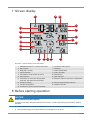
7 Screen display
12
10
11
8
19
1
18
17
16
14
15
9
6
5
4
3
7
2
13
Illustration3: Screen display for the base station
1 AM/PM information in 12-hour time mode 2 Symbol for radio signal
3 Moon phase 4 Weekday
5 Date (day - month) 6 Indoor temperature
7 Clima indication 8 Indoor humidity
9 Percipitation or barometric pressure 10 Wind speed
11 Wind direction 12 Wind indicator
13 Information on 'feels like' temperature,
wind chill, dew point and heat index
14 Beaufort scale for wind force classification
15 Outdoor humidity 16 Sensor signal strength indicator
17 Outdoor temperature 18 Weather forecast
19 Current time (hours:minutes:seconds)
8 Before starting operation
NOTICE
Avoid connectivity disruptions!
To avoid connectivity disruptions between the devices, consider the following points before starting
operation.
1. Place base station (receiver) and remote sensor (sender) together as close as possible.
2. Set up power supply for the base station and wait approx. 5 seconds.

16 / 20
3. Set up power supply for the remote sensor.
4. Position the base station and the remote sensor within the effective transmission range.
When changing batteries always change all batteries and replace them in the correct order, so the re-
mote connection can be re-established. If either of the devices is mains-powered, the power supply
must be disconnected for a short moment also for this device when exchanging the batteries. If batter-
ies are exchanged in only one of the devices (i.e. the remote sensor) the signal can’t be received or
can’t be received correctly.
Note, that the effective range is vastly affected by building materials and position of the main and re-
mote units. Due to external influences (various RC devices and other sources of interference), the
maximum distance can be greatly reduced. In such cases we suggest to position the main unit and the
remote sensor at other places. Sometimes all it takes is a relocation of one of these components of a
few inches! Though the remote unit is weather proof, it should be placed away from direct sunlight,
rain or snow.
9 Setting up power supply
Base unit
1. Remove the battery compartment cover.
2. Insert the batteries into the battery compartment. Ensure that the battery polarity (+/-) is correct.
3. Replace the battery compartment cover.
Remote sensor
4. Loosen the screw at the battery compartment cover with a small Philips screwdriver and remove
the cover.
5. Insert the batteries into the battery compartment. Ensure that the battery polarity (+/-) is correct.
6. Replace the cover and retighten it with the screw.
10 Assembling and installing the multifunctional
remote sensor
Depending on the desired location, the remote sensor can be installed in two different ways.
NOTICE!During the assembly make sure that the upper part of the wind vanve is minimum 1.5
meters off the ground. Use the circular level in the sensor head to ensure a level installation. The
windmill must point to the North.
Assembly on a vertical or horizontal wooden element
1. Slide one end of the assembly bar into the aperture below the sensor head.
2. Slide one screw through the bore hole and put on the nut on the opposite site. Tighten the screw
connection by hand.
3. Depending on the desired orientation, slide the opposite end of the assembly bar into the aperture
for vertical or horizontal mounting of the assembly base.
4. Slide another screw through the bore hole of the assembly base and put on the nut on the oppos-
ite site. Tighten the screw connection by hand.
5. Place the assembly base with its bottom site first on a wooden element. Use 4 wood screws to
tighten it.
Assembly on a vertical or horizontal tube
6. Repeat steps 1 to 4 as before.
7. Place the assembly base with its bottom site first on the tube. Push the tube bracket against the
tube from the opposite site.

17 / 20
8. Slide 4 screws through the bore holes of the assemby base and through the bore holes of the tube
bracket on the other site.
9. Put on the 4 nuts and tighten the screw connection by hand.
11 Signal transmission
The base station will automatically connect to the outdoor sensor. Press the SENSOR button to start a
manual search for the sensor. When the connection is successful, the sensor signal strength indicator
will be shown on the display.
Connection status display
Connection status Screen display
Good signal Reception symbol
Searching for a sensor Reception symbol flashes
No signal for 48 hours 'Er' (Error) is shown
Sensor low battery status, good signal Battery symbol is shown
12 Automatic time setting
After the power supply was established, the clock will automatically search for the radio signal. The
clock will automatically search for the radio signal.
If the radio signal is received correctly, the date and time will be set automatically and the radio control
signal icon turns on.
If the clock fails to receive the time signal, go ahead with the following steps:
1. Press RCC button on the base station until radio signal symbol flashes.
2. If the device is still not receiving the signal, the time must be set manually.
Read the detailed manual for more information about manual time and alarm setting (see download in-
formation on page 2).
13 Receiving measurements automatically
Once batteries are installed, the base station will display the measurement readings. Readings from
the remote sensor will be displayed within 3 minutes after powering it on.
Read the detailed manual for more information about readings (see download information on page 2).
14 EC Declaration of Conformity
Hereby, Bresser GmbH declares that the equipment type with item number 7002590 : is in compli-
ance with Directive: 2014/30/EU. The full text of the EU declaration of conformity is available at the
following internet address: www.bresser.de/download/7002590/CE/7002590_CE.pdf
15 Cleaning and maintenance
• Before cleaning the device, disconnect it from the power supply (remove plug or remove batteries)!
• Only clean the device externally using a dry cloth. Do not use cleaning solution to prevent damage
to the electronic parts.
Cleaning the rain collector (sinkhole)

18 / 20
1. Rotate the rain collector by 30° anticlockwise.
2. Gently remove the rain collector
3. Clean and remove any debris or insects.
4. Install all parts when they are fully clean and dried.
Cleaning the thermo/hygro sensor
5. Unscrew the 2 screws at the bottom of the radiation shield.
6. Gently pull out the shield.
7. Remove carefully any dirt or insects inside the sensor casing.
Note
The radiation shield comprises different parts inserted one inside another. Two bottom parts are
closed. Do not change their order! Do not let the sensors inside get wet!
• Clean the shield with water and remove any dirt or insects.
• Install all the parts back when they are fully clean and dried.
16 Disposal
Sort packaging into different materials for disposal. Contact the local waste disposal service
provider or environmental agency for information about appropriate waste management.
Do not dispose of electronic devices in the household garbage!
As per Directive 2012/19/EC of the European Parliament on waste electrical and electronic
equipment and its adaptation into German law, used electronic devices must be collected
separately and recycled in an environmentally friendly manner.
Do not dispose of batteries and rechargeable batteries with the household waste. You are leg-
ally required to return used batteries and rechargeable batteries. After they are used, the bat-
teries can be returned free of charge to our point of sale or to a nearby location (for example,
retailers or municipal collecting points).
Batteries and rechargeable batteries are marked with a symbol of a crossed-out dustbin and
the chemical symbol of the pollutant. “Cd” stands for Cadmium, “Hg” stands for mercury and
“Pb” stands for lead.
17 Warranty
The regular guarantee period is 2 years and begins on the day of purchase. To benefit from an exten-
ded voluntary guarantee period as stated on the gift box, registration on our website is required.
You can consult the full guarantee terms as well as information on extending the guarantee period and
details of our services at www.bresser.de/warranty_terms.


DE
AT
CH
BE
Bei Fragen zum Produkt und eventuellen
Reklamationen nehmen Sie bitte zunächst mit
dem Service-Center Kontakt auf, vorzugsweise
per E-Mail.
E-Mail: service@bresser.de
Telefon*: +49 28 72 80 74 210
BRESSER GmbH
Kundenservice
Gutenbergstr. 2
46414 Rhede
Deutschland
* Lokale Rufnummer in Deutschland (Die Höhe der Gebühren je
Telefonat ist abhängig vom Tarif Ihres Telefonanbieters); Anrufe
aus dem Ausland sind mit höheren Kosten verbunden.
GB
IE
Please contact the service centre first for any
questions regarding the product or claims,
preferably by e-mail.
e-mail: [email protected]
Telephone*: +44 1342 837 098
BRESSER UK Ltd
Unit 1 starborough Farm,
Starborough Road, Nr Marsh Green,
Edenbridge, Kent TN8 5RB
Great Britain
* Number charged at local rates in the UK (the amount you will be
charged per phone call will depend on the tariff of your phone
provider); calls from abroad will involve higher costs.
FR
BE
Si vous avez des questions concernant ce
produit ou en cas de réclamations, veuillez
prendre contact avec notre centre de services
(de préférence via e-mail).
e-mail: sav@bresser.fr
Téléphone*: +33 494 592 599
BRESSER France SARL
Pôle d'Activités de Nicopolis
260, rue des Romarins
83170 Brignoles
France
* Prix d'un appel local depuis la France ou Belgique
Service
NL
BE
Als u met betrekking tot het product vragen
of eventuele klachten heeft kunt u contact
opnemen met het service centrum (bij voorkeur
per e-mail).
e-mail: [email protected]
Teléfono*: +31 528 23 24 76
Folux B.V.
Smirnoffstraat 8
7903 AX Hoogeveen
Nederlands
* Het telefoonnummer wordt in het Nederland tegen lokaal tarief
in rekening gebracht. Het bedrag dat u per gesprek in rekening
gebracht zal worden, is afhankelijk van het tarief van uw telefoon
provider; gesprekken vanuit het buitenland zullen hogere kosten
met zich meebrengen.
ES
CA
PT
Si desea formular alguna pregunta sobre el
producto o alguna eventual reclamación, le
rogamos que se ponga en contacto con el
centro de servicio técnico (de preferencia por
e-mail).
e-mail: [email protected]
Teléfono*: +34 91 67972 69
BRESSER Iberia SLU
c/Valdemorillo,1 Nave B
P.I. Ventorro del cano
28925 Alcorcón Madrid
España
* Número local de España (el importe de cada llamada telefónica
dependen de las tarifas de los distribuidores); Las llamadas des del
extranjero están ligadas a costes suplementarios.
-
 1
1
-
 2
2
-
 3
3
-
 4
4
-
 5
5
-
 6
6
-
 7
7
-
 8
8
-
 9
9
-
 10
10
-
 11
11
-
 12
12
-
 13
13
-
 14
14
-
 15
15
-
 16
16
-
 17
17
-
 18
18
-
 19
19
-
 20
20


Bresser XXL Weather Center JC Bedienungsanleitung
- Typ
- Bedienungsanleitung
in anderen Sprachen
Verwandte Artikel
-
Bresser 7000017 Bedienungsanleitung
-
-
Bresser 9080500 - Colour Weather Center 5-in-1 National Geographic Bedienungsanleitung
-
-
-
-
-
-
-