Bresser 7000025000000 Bedienungsanleitung
- Kategorie
- Wecker
- Typ
- Bedienungsanleitung

Weather Station · Wetterstation ·
Thermo Hygro Quadro Neo
EN Instruction manual
DE Bedienungsanleitung

DE
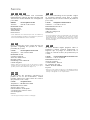
Besuchen Sie unsere Website über den folgenden QR Code oder Weblink um weitere Informationen
zu diesem Produkt oder die verfügbaren Übersetzungen dieser Anleitung zu finden.
EN
Visit our website via the following QR Code or web link to find further information on this product or
the available translations of these instructions.
FR
Si vous souhaitez obtenir plus d’informations concernant ce produit ou rechercher ce mode d’emploi en
d’autres langues, rendez-vous sur notre site Internet en utilisant le code QR ou le lien correspondant.
NL
Bezoek onze internetpagina via de volgende QR-code of weblink, voor meer informatie over dit
product of de beschikbare vertalingen van deze gebruiksaanwijzing.
ES
¿Desearía recibir unas instrucciones de uso completas sobre este producto en un idioma determinado?
Entonces visite nuestra página web utilizando el siguiente enlace (código QR) para ver las versiones
disponibles.
IT
Desidera ricevere informazioni esaustive su questo prodotto in una lingua specifica? Venga a visitare
il nostro sito Web al seguente link (codice QR Code) per conoscere le versioni disponibili.
www.bresser.de/P7000025000000
www.bresser.de/warranty_terms
GARANTIE · WARRANTY · GARANTÍA · GARANZIA
DE
Besuchen Sie unsere Website über den folgenden QR Code oder Weblink um weitere Informationen
zu diesem Produkt oder die verfügbaren Übersetzungen dieser Anleitung zu finden.
EN
Visit our website via the following QR Code or web link to find further information on this product or
the available translations of these instructions.
FR
Si vous souhaitez obtenir plus d’informations concernant ce produit ou rechercher ce mode d’emploi en
d’autres langues, rendez-vous sur notre site Internet en utilisant le code QR ou le lien correspondant.
NL
Bezoek onze internetpagina via de volgende QR-code of weblink, voor meer informatie over dit
product of de beschikbare vertalingen van deze gebruiksaanwijzing.
ES
¿Desearía recibir unas instrucciones de uso completas sobre este producto en un idioma determinado?
Entonces visite nuestra página web utilizando el siguiente enlace (código QR) para ver las versiones
disponibles.
IT
Desidera ricevere informazioni esaustive su questo prodotto in una lingua specifica? Venga a visitare
il nostro sito Web al seguente link (codice QR Code) per conoscere le versioni disponibili.
www.bresser.de/P7000025000000
www.bresser.de/warranty_terms
GARANTIE · WARRANTY · GARANTÍA · GARANZIA


4 / 40
1 Imprint (German)
Bresser GmbH
Gutenbergstr. 2
46414
Rhede
Germany
www.bresser.de
For any warranty claims or service enquiries, please refer to
the information on "Warranty" and "Service" in this docu-
mentation. We apologize for any inconvenience caused by
the fact that we cannot process enquiries or submissions
sent directly to the manufacturer's address.
Errors and technical changes excepted.
© 2021 Bresser GmbH
All rights reserved.
The reproduction of this documentation - even in extracts -
in any form (e.g. photocopy, print, etc.) as well as the use
and distribution by means of electronic systems (e.g. image
file, website, etc.) without the prior written permission of the
manufacturer is prohibited.
The designations and brand names of the respective com-
panies used in this documentation are generally protected
by trade, trademark and/or patent law in Germany, the
European Union and/or other countries.

5 / 40
2 Validity note
This documentation is valid for the products with the follow-
ing article numbers:
7000025000000
Manual version: 0421
Manual designation:
Manual_7000025000000_Thermo-Hygro-Quadro-Neo_en-
de_BRESSER_v042021a
Always provide information when requesting service.
3 About this Instruction Manual
NOTICE
These operating instructions are to be considered a
component of the device.
Read the safety instructions and the operating manual care-
fully before using this device.
Keep this instruction manual in a safe place for future refer-
ence. When the device is sold or given to someone else,
the instruction manual must be provided to the new owner/
user of the product.

6 / 40
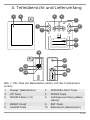
4 Parts overview and scope of
delivery
+
+
AAA/LR03
AAA/LR03
AAA/LR03
+
CH1
CH
3 2 1
°C/°F
AAA/LR03
AAA/LR03
+
+
2
3
4
8
9
7
10
11
65
1
13
12
14
15
16
17
18
19
B
A
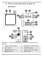
Illustration1: All parts of base station (top) and wireless sensor
(bottom)
1 Display* (base station) 2 [SNOOZE / LIGHT] button
3 [UP ] button 4 [DOWN] buttons
5 [ROOM] buttons (1-3) 6 Wall mount (base station)
7 [RESET] knob 8 [SET] button

7 / 40
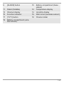
9 [ALARM] button 10 Battery compartment (base
station)
11 Stand (foldable) 12 Temperature display
13 Channel display 14 Humidity display
15 Function indicator 16 Wall mount (wireless sensor)
17 [°C/°F] button 18 Channel slider
19 Battery compartment (wire-
less sensor)

8 / 40
Delivery content
Base station (A), wireless sensor (3 pcs.)(B)
Also required (not included):
9 pcs. Mignon batteries (1.5V, type AAA/LR03), small Phil-
lips screwdriver
*For more information, refer to the chapter "Screen display"
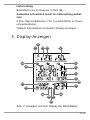
5 Screen display
DST
AM
4
1
3
5
6
7
8
9
11
10
14
2
12
16
17
18
20
19
13
15
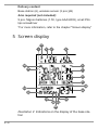
Illustration2: Indications on the display of the base sta-
tion

9 / 40
1 Battery status (base sta-
tion)
2 Symbol for the indoor
display
3 Trend arrow 4 Indoor temperature
5 Indoor humidity (in %) 6 Battery status (wireless
sensor)
7 Outdoor humidity (wire-
less sensor)
8 Outdoor temperature
(wireless sensor)
9 Room description (for
sensor location)
10 Symbol for active
snooze function
11 current time or alarm
time
12 AM/PM display in 12-
hour mode
13 Symbol for enabled
alarm
14 Symbol for active time
zone setting
15 Radio clock signal re-
ception icon
16 Symbol for active day-
light saving time
17 Current date 18 Current day of the week
19 Symbol for connection
to the wireless sensor
20 Channel of the radio
sensor
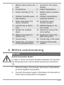
6 Before commissioning
NOTICE
Avoid connection faults!
In order to avoid connection problems between the devices,
the following points must be observed during commission-
ing.
1. Place the base unit (receiver) and sensor (transmitter)
as close together as possible.
2. Connect the power supply to the base unit and wait un-
til the indoor temperature is displayed.

10 / 40
3. Establish power supply for the sensor.
4. Set up/operate the base unit and sensor within the ef-
fective transmission range.
5. Make sure that the base unit and the radio sensor are
set to the same channel.
When changing the batteries, always remove the batteries
in both the base unit and the sensor and reinsert them in
the correct order so that the radio connection can be re-es-
tablished. If one of the two devices is operated via a mains
power connection, the power connection for this device
must also be disconnected briefly when changing the bat-
tery. If, for example, only the batteries in the sensor are re-
placed, the signal cannot be received or can no longer be
received correctly.
Note that the actual range depends on the building materi-
als used in the building and the position of the base unit and
outdoor sensor. External influences (various radio transmit-
ters and other sources of interference) can greatly reduce
the possible range. In such cases, we recommend finding
other locations for both the base unit and the outdoor
sensor. Sometimes a shift of just a few centimetres is
enough!
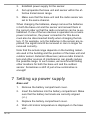
7 Setting up power supply
Base unit
1. Remove the battery compartment cover.
2. Insert the batteries into the battery compartment. Make
sure that the battery terminals are correctly aligned
(+/-).
3. Replace the battery compartment cover.
4. Wait until indoor temperature is displayed on the base
unit.

11 / 40
Wireless sensor
5. Remove the screws on the battery compartment cover
with a suitable Phillips screwdriver and remove the bat-
tery compartment cover.
6. Move the channel slider to the desired channel.
NOTICE!This weather station can be operated with
up to 3 wireless sensors. Each connected wireless
sensor must be operated on a different channel. If
only one wireless sensor is connected, it should be
operated on channel 1.
7. Insert the batteries into the battery compartment. Make
sure that the battery terminals are correctly aligned
(+/-).
8. Replace and screw on the battery compartment cover.
8 Battery level indicator
1. When the level of the batteries in the base station or in
the wireless sensor reaches a critical level, the battery
level symbol appears in the appropriate area on the
display.
2. When replacing one set of batteries, always remove the
batteries from the other part of the unit and reinsert
them in the correct order (see chapter "Setting up
power supply"). Replace the batteries to be changed in
the corresponding part of the device with a completely
new set with full capacity. This ensures that the con-
nection between the devices will be reestablished again
correctly.

12 / 40
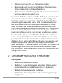
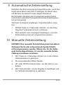
9 Automatic time setting
After the power is restored, the unit automatically searches
for the radio signal. It takes about 3-8 minutes to complete
this process.
If the radio signal is received correctly, the date and time
are set automatically and the reception symbol is displayed.
If no radio signal is received, proceed as follows:
1. Press the DOWN button for approx. 2 seconds to initi-
ate the reception of the radio signal again.
2. If no radio signal is still received, the time setting must
be made manually.
10 Manual time setting
NOTICE!A manual time setting cannot be made when
the time signal search is active (the corresponding sym-
bol flashes). Wait until the time signal search is com-
pleted to make the manual time setting.
1. Press the SET button for approx. 3 seconds to enter
the time setting mode.
2. Digits to be set are flashing.
3. Press UP or DOWN button to change the value.
4. Press the SET button to confirm and switch to the next
setting.
5. Settings sequence: Hours > Minutes > 12/24 hour
mode > Year > Month > Day > Time zone > Language
6. Finally, press the SET button to save the settings and
exit settings mode.

13 / 40
*The language setting refers to the days of the week as well
as to the room names. Available languages: English, Ger-
man, French, Spanish, Italian, Danish, Swedish
11 Time zone setting
The time zone is set as part of the manual time setting. You
can also find more detailed information in the chapter
"Manual time setting".
1. Press the SET button for approx. 3 seconds to enter
the time setting mode.
2. Press the SET button several times until the display
shows the setting for the time offset (the factory setting
is '00').
3. Press UP or DOWN button to select the desired time
deviation in hours (-23 up to +23 hours).
4. Press the SET button for approx. 3 seconds to confirm
the selected time deviation.
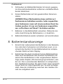
12 Alarm setting
NOTICE!The alarm setting cannot be made when the
time signal search is active (the corresponding symbol
flashes). Wait until the time signal search is completed
to be able to set the manual alarm.
1. Press the Alarm button to display the alarm time.
2. Press the Alarm button for approx. 2 seconds to enter
the alarm time settings mode.
3. Digits to be set are flashing.
4. Press UP or DOWN button to change the value.

14 / 40
5. Press the ALARM button to confirm the entry and move
to the next setting.
6. Settings sequence: Hours > minutes
7. Finally, press the ALARM button to save the settings
and exit the settings mode.
Enable/disable the alarm
8. In normal display mode, press the ALARM button to
display the currently set alarm time. The alarm time and
the alarm status (ON/OFF) are displayed.
9. Press the UP button to activate the wake-up call (ON).
The
symbol will displayed on the LCD.
10. Press the SET button again to deactivate wake-up call.
The
symbol is no longer displayed.
13 Snooze function
1. When the alarm tone sounds, press the SNOOZE/
LIGHT button on the top of the base station to activate
the snooze function. The alarm sounds again after 5
minutes.
2. When the alarm sounds, press any other button to stop
the alarm until the set alarm time is reached again.
3. If no button is pressed, the alarm is automatically
switched off after 2 minutes.

15 / 40
NOTICE!The snooze function can be reactivated up to
seven times before the alarm is automatically stopped.
14 Change room name
NOTICE!The room name cannot be changed when the
time signal search is active (the corresponding icon
flashes). Wait until the time signal search is completed
to be able to change the room name.
1. Press the ROOM button of the desired wireless sensor.
The room name flashes.
2. Press the ROOM button repeatedly to select one of the
5 preset room names. Alternatively, continue with 3. or
wait approx. 5 seconds until the change has been
saved automatically. The display stops flashing.
3. Press the UP button to switch to the entry of a free
room designation. "_" flashes.
4. Press the UP button until the desired input value
flashes. Possible input values: A-Z, 0-9, _ > < / * -
5. Press the ROOM button again to switch to the next in-
put value and enter it as described under 4.
6. Finally, press the ROOM button to save the entry. If no
entry is made within 5 seconds, the settings made up to
this point are automatically saved. In both cases the
display stops flashing and the free input is stored.

16 / 40
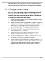
15 Receiving measurements
automatically
Once batteries are installed, the base station will display the
measurement readings. Readings from the remote sensor
will be displayed within 3 minutes after powering it on.
16 Display change °C/°F
• Base unit
In normal display mode, press the DOWN button to toggle
between °C and °F.
Wireless sensor
Open the battery compartment.
Press the °C/°F button to toggle between °C and °F.
Close the battery compartment again.
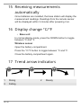
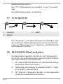
17 Trend arrow indicators
1
2
3
1 Rising 2 Steady
3 Falling

17 / 40
The temperature and humidity trend indicator shows the
trends of changes in the forthcoming few minutes. Arrows
indicate a rising, steady or falling trend.
18 MAX/MIN weather data
The maximum and minimum readings for indoor and out-
door temperature as well as for the humidity are stored by
the base station over a period of 24 hours:
1. Press the UP button several times to display the stored
values one after the other.
2. Display sequence: Maximum readings (MAX) > Min-
imum readings (MIN) > Current readings
3. Press the UP button for approx. 2 seconds to perman-
ently delete all stored readings.

18 / 40
NOTICE!If a reading is below the recordable range, the
display shows "LL.L". If a reading is above the record-
able range, the display shows "HH.H".
19 Backlight
Press SNOOZE/LIGHT button to activate backlight for 5
seconds.
20 EC declaration of conformity
A "Declaration of conformity" in accordance with the
applicable directives and corresponding standards
has been prepared by Bresser GmbH
. The full text of
the EC declaration of conformity is available at the
following Internet address: www.bresser.de/down-
load/7000025000000/CE/7000025000000_CE.pdf
21 UKCA Declaration of Conformity
Bresser GmbH has issued a "Declaration of Con-
formity" in accordance with applicable guidelines and
corresponding standards. The full text of the UKCA
declaration of conformity is available at the following
internet address: www.bresser.de/down-
load/7000025000000/
UKCA/7000025000000_UKCA.pdf
Bresser UK Ltd. • Suite 3G, Eden House, Enter-
prise Way, Edenbridge, Kent TN8 6Hf, Great Britain

19 / 40
22 Warranty
The regular warranty period is 5 years and starts on the day
of purchase. For full warranty terms and services, please
visit www.bresser.de/warranty_terms
.
23 Disposal
Dispose of the packaging materials properly, accord-
ing to their type, such as paper or cardboard. Contact
your local waste-disposal service or environmental au-
thority for information on the proper disposal.
Do not dispose of electronic devices in the household
garbage!
According to the European Directive 2012/19/EU on
Waste Electrical and Electronic Equipment and its
transposition into national law, used electrical equip-
ment must be collected separately and recycled in an
environmentally sound manner.

20 / 40
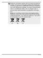
Batteries and rechargeable batteries must not be dis-
posed of with household waste. You are legally obliged
to return used batteries and accumulators and can re-
turn the batteries after use either in our sales outlet or
in the immediate vicinity (e.g. in the trade or in muni-
cipal collection points) free of charge.
Batteries and accumulators are marked with a crossed-
out dustbin and the chemical symbol of the pollutant,
"Cd" stands for cadmium, "Hg" stands for mercury and
"Pb" stands for lead.
Seite wird geladen ...
Seite wird geladen ...
Seite wird geladen ...
Seite wird geladen ...
Seite wird geladen ...
Seite wird geladen ...
Seite wird geladen ...
Seite wird geladen ...
Seite wird geladen ...
Seite wird geladen ...
Seite wird geladen ...
Seite wird geladen ...
Seite wird geladen ...
Seite wird geladen ...
Seite wird geladen ...
Seite wird geladen ...
Seite wird geladen ...
Seite wird geladen ...
Seite wird geladen ...
Seite wird geladen ...
-
 1
1
-
 2
2
-
 3
3
-
 4
4
-
 5
5
-
 6
6
-
 7
7
-
 8
8
-
 9
9
-
 10
10
-
 11
11
-
 12
12
-
 13
13
-
 14
14
-
 15
15
-
 16
16
-
 17
17
-
 18
18
-
 19
19
-
 20
20
-
 21
21
-
 22
22
-
 23
23
-
 24
24
-
 25
25
-
 26
26
-
 27
27
-
 28
28
-
 29
29
-
 30
30
-
 31
31
-
 32
32
-
 33
33
-
 34
34
-
 35
35
-
 36
36
-
 37
37
-
 38
38
-
 39
39
-
 40
40


Bresser 7000025000000 Bedienungsanleitung
- Kategorie
- Wecker
- Typ
- Bedienungsanleitung
in anderen Sprachen
- English: Bresser 7000025000000 Owner's manual
Verwandte Artikel
-
Bresser 7000013 Bedienungsanleitung
-
Bresser 7007201 Bedienungsanleitung
-
-
-
-
-
Bresser VA colour LCD Weather Station incl. 3 Sensors Bedienungsanleitung
-
-
-
Bresser 7000023 Bedienungsanleitung