Yamaha DTX-900 Bedienungsanleitung
- Kategorie
- Musikinstrumente
- Typ
- Bedienungsanleitung
Dieses Handbuch eignet sich auch für

Owner’s Manual
EN

2
DTX900 Owner’s Manual
PLEASE KEEP THIS MANUAL
This product utilizes batteries or an external power supply (adapter). DO
NOT connect this product to any power supply or adapter other than one
described in the manual, on the name plate, or specifically recom-
mended by Yamaha.
WARNING:
Do not place this product in a position where anyone could
walk on, trip over ,or roll anything over power or connecting cords of any
kind. The use of an extension cord is not recommended! If you must use
an extension cord, the minimum wire size for a 25’ cord (or less ) is 18
AWG. NOTE: The smaller the AWG number ,the larger the current han-
dling capacity. For longer extension cords, consult a local electrician.
This product should be used only with the components supplied or; a
cart, rack, or stand that is recommended by Yamaha. If a cart, etc., is
used, please observe all safety markings and instructions that accom-
pany the accessory product.
SPECIFICATIONS SUBJECT TO CHANGE:
The information contained in this manual is believed to be correct at the
time of printing. However, Yamaha reserves the right to change or modify
any of the specifications without notice or obligation to update existing
units.
This product, either alone or in combination with an amplifier and head-
phones or speaker/s, may be capable of producing sound levels that
could cause permanent hearing loss. DO NOT operate for long periods
of time at a high volume level or at a level that is uncomfortable. If you
experience any hearing loss or ringing in the ears, you should consult an
audiologist.
IMPORTANT: The louder the sound, the shorter the time period before
damage occurs.
Some Yamaha products may have benches and / or accessory mounting
fixtures that are either supplied with the product or as optional accesso-
ries. Some of these items are designed to be dealer assembled or
installed. Please make sure that benches are stable and any optional fix-
tures (where applicable) are well secured BEFORE using.
Benches supplied by Yamaha are designed for seating only. No other
uses are recommended.
NOTICE:
Service charges incurred due to a lack of knowledge relating to how a
function or effect works (when the unit is operating as designed) are not
covered by the manufacturer’s warranty, and are therefore the owners
responsibility. Please study this manual carefully and consult your dealer
before requesting service.
ENVIRONMENTAL ISSUES:
Yamaha strives to produce products that are both user safe and environ-
mentally friendly. We sincerely believe that our products and the produc-
tion methods used to produce them, meet these goals. In keeping with
both the letter and the spirit of the law, we want you to be aware of the
following:
Battery Notice:
This product MAY contain a small non-rechargeable battery which (if
applicable) is soldered in place. The average life span of this type of bat-
tery is approximately five years. When replacement becomes necessary,
contact a qualified service representative to perform the replacement.
This product may also use “household” type batteries. Some of these
may be rechargeable. Make sure that the battery being charged is a
rechargeable type and that the charger is intended for the battery being
charged.
When installing batteries, do not mix batteries with new, or with batteries
of a different type. Batteries MUST be installed correctly. Mismatches or
incorrect installation may result in overheating and battery case rupture.
Warning:
Do not attempt to disassemble, or incinerate any battery. Keep all batter-
ies away from children. Dispose of used batteries promptly and as regu-
lated by the laws in your area. Note: Check with any retailer of
household type batteries in your area for battery disposal information.
Disposal Notice:
Should this product become damaged beyond repair, or for some reason
its useful life is considered to be at an end, please observe all local,
state, and federal regulations that relate to the disposal of products that
contain lead, batteries, plastics, etc. If your dealer is unable to assist
you, please contact Yamaha directly.
NAME PLATE LOCATION:
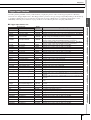
The name plate is located on the bottom of the product. The model num-
ber, serial number, power requirements, etc., are located on this plate.
You should record the model number, serial number, and the date of pur-
chase in the spaces provided below and retain this manual as a perma-
nent record of your purchase.
Model
Serial No.
Purchase Date
SPECIAL MESSAGE SECTION
92-BP
(bottom)

DTX900 Owner’s Manual
3
1. IMPORTANT NOTICE: DO NOT MODIFY THIS UNIT!
This product, when installed as indicated in the instructions con-
tained in this manual, meets FCC requirements. Modifications not
expressly approved by Yamaha may void your authority, granted by
the FCC, to use the product.
2. IMPORTANT:
When connecting this product to accessories and/
or another product use only high quality shielded cables. Cable/s
supplied with this product MUST be used. Follow all installation
instructions. Failure to follow instructions could void your FCC
authorization to use this product in the USA.
3. NOTE:
This product has been tested and found to comply with the
requirements listed in FCC Regulations, Part 15 for Class “B” digital
devices. Compliance with these requirements provides a reason-
able level of assurance that your use of this product in a residential
environment will not result in harmful interference with other elec-
tronic devices. This equipment generates/uses radio frequencies
and, if not installed and used according to the instructions found in
the users manual, may cause interference harmful to the operation
of other electronic devices. Compliance with FCC regulations does
* This applies only to products distributed by YAMAHA CORPORATION OF AMERICA. (class B)
not guarantee that interference will not occur in all installations. If
this product is found to be the source of interference, which can be
determined by turning the unit “OFF” and “ON”, please try to elimi-
nate the problem by using one of the following measures:
Relocate either this product or the device that is being affected by
the interference.
Utilize power outlets that are on different branch (circuit breaker or
fuse) circuits or install AC line filter/s.
In the case of radio or TV interference, relocate/reorient the
antenna. If the antenna lead-in is 300 ohm ribbon lead, change the
lead-in to co-axial type cable.
If these corrective measures do not produce satisfactory results,
please contact the local retailer authorized to distribute this type of
product. If you can not locate the appropriate retailer, please con-
tact Yamaha Corporation of America, Electronic Service Division,
6600 Orangethorpe Ave, Buena Park, CA90620
The above statements apply ONLY to those products distributed by
Yamaha Corporation of America or its subsidiaries.
FCC INFORMATION (U.S.A.)
* This applies only to products distributed by
YAMAHA CORPORATION OF AMERICA.
COMPLIANCE INFORMATION STATEMENT
(DECLARATION OF CONFORMITY PROCEDURE)
Responsible Party : Yamaha Corporation of America
Address : 6600 Orangethorpe Ave., Buena Park, Calif. 90620
Telephone : 714-522-9011
Type of Equipment : DRUM TRIGGER MODULE
Model Name : DTX900
This device complies with Part 15 of the FCC Rules.
Operation is subject to the following two conditions:
1) this device may not cause harmful interference, and
2) this device must accept any interference received including interference
that may cause undesired operation.
See user manual instructions if interference to radio reception is sus-
pected.
(FCC DoC)
IMPORTANT NOTICE FOR THE UNITED KINGDOM
Connecting the Plug and Cord
IMPORTANT. The wires in this mains lead are coloured in
accordance with the following code:
BLUE : NEUTRAL
BROWN : LIVE
As the colours of the wires in the mains lead of this apparatus
may not correspond with the coloured makings identifying the
terminals in your plug proceed as follows:
The wire which is coloured BLUE must be connected to the
terminal which is marked with the letter N or coloured BLACK.
The wire which is coloured BROWN must be connected to the
terminal which is marked with the letter L or coloured RED.
Making sure that neither core is connected to the earth termi-
nal of the three pin plug.
Information for Users on Collection and Disposal of Old Equipment
This symbol on the products, packaging, and/or accompanying documents means that used electrical and electronic products should not be
mixed with general household waste.
For proper treatment, recovery and recycling of old products, please take them to applicable collection points, in accordance with your national
legislation and the Directives 2002/96/EC.
By disposing of these products correctly, you will help to save valuable resources and prevent any potential negative effects on human health
and the environment which could otherwise arise from inappropriate waste handling.
For more information about collection and recycling of old products, please contact your local municipality, your waste disposal service or the
point of sale where you purchased the items.
[For business users in the European Union]
If you wish to discard electrical and electronic equipment, please contact your dealer or supplier for further information.
[Information on Disposal in other Countries outside the European Union]
This symbol is only valid in the European Union. If you wish to discard these items, please contact your local authorities or dealer and ask for the
correct method of disposal.
OBSERVERA!
Apparaten kopplas inte ur växelströmskällan (nätet) så länge som den ar ansluten till vägguttaget,
även om själva apparaten har stängts av.
ADVARSEL:
Netspændingen til dette apparat er IKKE afbrudt, sålæenge netledningen siddr i en
stikkontakt, som er t endt — også selvom der or slukket på apparatets afbryder.
VAROITUS:
Laitteen toisiopiiriin kytketty käyttökytkin ei irroita koko laitetta verkosta.
(standby)
• This applies only to products distributed by
Yamaha Music U.K. Ltd.
(2 wires)

4
DTX900 Owner’s Manual
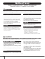
PRECAUTIONS
PLEASE READ CAREFULLY BEFORE PROCEEDING
* Please keep this manual in a safe place for future reference.
WARNING
Always follow the basic precautions listed below to avoid the possibility of serious injury or even death from electrical
shock, short-circuiting, damages, fire or other hazards. These precautions include, but are not limited to, the following:
• Do not place the power cord near heat sources such as heaters or
radiators, and do not excessively bend or otherwise damage the
cord, place heavy objects on it, or place it in a position where
anyone could walk on, trip over, or roll anything over it.
• Only use the voltage specified as correct for the instrument. The
required voltage is printed on the name plate of the instrument.
• Use the specified adaptor (page 155) only. Using the wrong adaptor
can result in damage to the instrument or overheating.
• Check the electric plug periodically and remove any dirt or dust
which may have accumulated on it.
• This instrument contains no user-serviceable parts. Do not open the
instrument or attempt to disassemble or modify the internal
components in any way. If it should appear to be malfunctioning,
discontinue use immediately and have it inspected by qualified
Yamaha service personnel.
• Do not expose the instrument to rain, use it near water or in damp or
wet conditions, or place containers on it containing liquids which
might spill into any openings. If any liquid such as water seeps into
the instrument, turn off the power immediately and unplug the
power cord from the AC outlet. Then have the instrument inspected
by qualified Yamaha service personnel.
• Never insert or remove an electric plug with wet hands.
• Do not put burning items, such as candles, on the unit.
A burning item may fall over and cause a fire.
• When one of the following problems occur, immediately turn off the
power switch and disconnect the electric plug from the outlet. Then
have the device inspected by Yamaha service personnel.
• The power cord or plug becomes frayed or damaged.
• It emits unusual smells or smoke.
• Some object has been dropped into the instrument.
• There is a sudden loss of sound during use of the instrument.
CAUTION
Always follow the basic precautions listed below to avoid the possibility of physical injury to you or others, or damage
to the instrument or other property. These precautions include, but are not limited to, the following:
• Do not connect the instrument to an electrical outlet using a
multiple-connector. Doing so can result in lower sound quality, or
possibly cause overheating in the outlet.
• When removing the electric plug from the instrument or an outlet,
always hold the plug itself and not the cord. Pulling by the cord can
damage it.
• Remove the electric plug from the outlet when the instrument is not
to be used for extended periods of time, or during electrical storms.
• Do not place the instrument in an unstable position where it might
accidentally fall over.
• Before moving the instrument, remove all connected cables.
• When setting up the product, make sure that the AC outlet you are
using is easily accessible. If some trouble or malfunction occurs,
immediately turn off the power switch and disconnect the plug from
the outlet. Even when the power switch is turned off, electricity is
still flowing to the product at the minimum level. When you are not
using the product for a long time, make sure to unplug the power
cord from the wall AC outlet.
• Use only the stand/rack specified for the instrument. When attaching
the stand or rack, use the provided screws only. Failure to do so
could cause damage to the internal components or result in the
instrument falling over.
Power supply/AC power adaptor
Do not open
Water warning
Fire warning
If you notice any abnormality
Power supply/AC power adaptor
Location
(7)-1
1/2

DTX900 Owner’s Manual
5
• Before connecting the instrument to other electronic components,
turn off the power for all components. Before turning the power on
or off for all components, set all volume levels to minimum.
• Be sure to set the volumes of all components at their minimum
levels and gradually raise the volume controls while playing the
instrument to set the desired listening level.
• Never insert or drop paper, metallic, or other objects into the gaps
on the panel.
• Do not rest your weight on, or place heavy objects on the
instrument, and do not use excessive force on the buttons, switches
or connectors.
• Do not use the instrument/device or headphones for a long period of
time at a high or uncomfortable volume level, since this can cause
permanent hearing loss. If you experience any hearing loss or
ringing in the ears, consult a physician.
Always turn the power off when the instrument is not in use.
Even when the power switch is in the “STANDBY” position, electricity is still flowing to the instrument at the minimum level. When you are not using
the instrument for a long time, make sure you unplug the power cord from the wall AC outlet.
Connections Handling caution
Yamaha cannot be held responsible for damage caused by improper use or modifications to the instrument, or data that is lost or destroyed.
NOTICE
To avoid the possibility of damage to the product, data or other property, follow the notices below.
■
Handling and Maintenance
• Do not use the instrument in the vicinity of a TV, radio, stereo equipment, mobile phone, or other electric devices. Otherwise, the
instrument, TV, or radio may generate noise.
• Do not expose the instrument to excessive dust or vibrations, or extreme cold or heat (such as in direct sunlight, near a heater, or in a car
during the day) to prevent the possibility of panel disfiguration or damage to the internal components.
• Do not place vinyl, plastic or rubber objects on the instrument, since this might discolor the panel or keyboard.
• When cleaning the instrument, use a soft, dry or slightly damp cloth. Do not use paint thinners, solvents, cleaning fluids, or chemical-
impregnated wiping cloths.
■
Saving data
• DRAM data (page 76) is lost when you turn off the power to the instrument. Save the data to external USB storage device.
•To protect against data loss through media damage, we recommend that you save your important data onto two USB storage devices.
■
About the latest Firmware Version
Yamaha may from time to time update firmware of the product without notice for improvement. We recommend that you check our web site
for later releases and upgrade your firmware of the DTX900.
http://www.yamaha.co.jp/english/product/drums/ed/
Note that the explanations in this Owner’s Manual apply to the version of firmware when this Owner’s Manual was produced. For details about
functions added in later releases, refer to the above website.
■
About the pads
This Owner’s Manual described the model names of the drum pads which can be connected to the DTX900. Note that these were the latest
models at the time this Owner’s Manual was produced. For details about more recently released models, refer to the following website.
http://www.yamaha.co.jp/english/product/drums/ed/
(7)-2
2/2

6
DTX900 Owner’s Manual
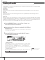
Introduction
Thank you for purchasing the YAMAHA DTX900.
The new DTX900 incorporates the highly acclaimed AWM2 tone generator
and a sophisticated music sequencer.
In addition to the functions of its predecessor, DTX900 provides full support of the current
Yamaha trigger products and also sports a USB terminal for MIDI connections (in addition to conventional MIDI
connectors) — and has a built-in sampling feature that allows you to create your own Drum Voices.
The instrument is ideal for virtually any application — live performance, rhythm training, music creation and
studio recording. To get the most out of your DTX900, please read this manual carefully. After reading through
the manual, make sure to store it in a safe place so that you can refer back to it again as needed.
Included Accessories
●
AC Power Adaptor
●
Module stand
●
Module stand fastening screws (4; included)
●
Owner’s Manual (this document)
●
Data List
●
DVD-ROM* (containing software)
* For details on the bundled DVD-ROM, see page 159.
Information
■
About copyrights
• Copying of the commercially available musical data including but not limited to MIDI data and/or audio data is strictly prohibited
except for your personal use.
• This product incorporates and bundles computer programs and contents in which Yamaha owns copyrights or with respect to which
it has license to use others’ copyrights. Such copyrighted materials include, without limitation, all computer software, style files,
MIDI files, WAVE data, musical scores and sound recordings. Any unauthorized use of such programs and contents outside of per-
sonal use is not permitted under relevant laws. Any violation of copyright has legal consequences. DON’T MAKE, DISTRIBUTE
OR USE ILLEGAL COPIES.
■
About functions/data bundled with the instrument
• This device is capable of using various types/formats of music data by optimizing them to the proper format music data for use with
the device in advance. As a result, this device may not play them back precisely as their producers or composers originally intended.
■
About this manual
• The contents of this Owner’s Manual and the copyrights thereof are under exclusive ownership by Yamaha Corporation.
• The illustrations and LCD screens as shown in this manual are for instructional purposes only, and may appear somewhat different
from those on your instrument.
• The company names and product names in this manual are the trademarks or registered trademarks of their respective companies.

DTX900 Owner’s Manual
7
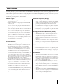
Main Features
Designed primarily for professional drummers, the DTX900 has a Drum Trigger feature, a 64-note polyphonic Tone Gener-
ator, a built-in Sampling feature that lets you expand the available sounds, a high-performance Metronome (Click) feature and
a built-in music sequencer that enables recording and playback of rhythm or accompaniment patterns, and even lets you create
an entire Song. The DTX900 is an exceptionally versatile instrument that can be used in a variety of situations such as live
performance, personal practice, and much more.
■
Drum Trigger
• The DTX900 drum trigger module is compatible with the
new pads (XP series.)
• Built into the unit are 15 Trigger Input jacks and a Hi-Hat
Controller jack.
• The instrument also features jacks that are compatible with
two-zone or three-zone pads (pads that transmit different
signals depending on the area that is hit). Moreover, the
snare drum jack is compatible with pad-controller-equipped
pads. This lets you adjust the ‘virtual’ snares and the tun-
ing—just as you would with a snare drum. All in all, the
DTX900 offers virtually the same playability, expressive-
ness and functionality that you get in an acoustic drum kit.
• By combining the Stack function, which lets you play mul-
tiple voices (MIDI notes) at the same time, along with the
Alternate function, which lets you play a sequence of the
Stack program, you can create complex performances and
play passages in realtime that would otherwise be impossi-
ble on conventional acoustic drums.
■
Tone Generator
• The DTX900 is equipped with a high-quality, 16-bit AWM2
(PCM) tone generator with 64-voice polyphony that pro-
duces dynamic voices or exceptional realism.
• The instrument has a wide variety of Voices including
authentic acoustic drums, unique electronic percussion,
sound effects, and normal keyboard Voices. It can also be
used as a high-quality drum tone generator along with vari-
ous MIDI devices, even without using the Drum Pads.
• Also included in the unit are 50 preset Drum Kits which
contain natural, authentic sounding acoustic Drum Kits, and
cover a wide range of music genres, such as rock, funk,
jazz, reggae, Latin, etc. Moreover, User kit memory is avail-
able for storing 50 sets. With this, you can set up your own
original Drum Kits using the various Drum Voices.
• The Sampling feature lets you record the audio signal to the
DTX900 or load the audio file from the USB storage device
to create your original Voice. The created Voice can be
assigned to the Drum Kit as desired.
• The instrument is equipped with a Variation Effect which
can be used for each Drum Kit as well as Reverb, Chorus
and Master Effects which can be used for the entire
DTX900. In addition, an Insertion Effect for the sound input
via the AUX IN/SAMPLING IN jack is provided, allowing
you to adjust the quality of AUX IN/SAMPLING IN sound
or record an audio signal to which the Insertion Effect is
applied to the DTX900 in the Sampling mode.
■
Music Sequencer (Song)
• The built-in sequencer contains a wide variety of Preset
Songs. The Mute function lets you turn on/off the rhythm
(drum & percussion sound) part, bass part and other accom-
paniment part individually, or turn each track on/off.
• The DTX900 also allows you to record your performance in
real time and allows you to play along with the Song data
while muting the original drum part.
•Four Pad Songs can be individually controlled and simulta-
neously played by trigger input from the pads.
■
High-performance Metronome (Click)
• The DTX900 provides a comprehensive, multi-function
metronome, allowing various click settings such as voice
and tuning for each beat timing. Furthermore, you can
change the accent timing and use the Measure Break feature
that alternates click playback between on and off (mute)
repeatedly.
• The Groove Check Function checks and provides instant
feedback on your rhythmic skills—a powerful tool for
improving your technique. It includes a Rhythm Gate func-
tion that produces sounds only if your timing is accurate.
■
Chain
• Programming a Chain sequence lets you call up the Drum
Kit number, Song number and Click settings (tempo and
beat) in order during your live performance. Each step in
the programmed Chain can be called up by hitting the pad.
■
Interfaces
• The USB terminal and MIDI connectors on the rear panel
let you connect a computer and other MIDI devices to the
DTX900. These enable fast, efficient and comprehensive
music-creation capabilities, letting you play sounds from an
external tone generator as well as record your own perfor-
mance using the included Cubase AI.
• Each of the six INDIVIDUAL OUTPUT jacks can sepa-
rately output any specified Drum Voice such as Snare and
Tom to send each instrument signal to an external mixer for
live performance or recording session. In addition, a Digital
Output (S/PDIF) terminal lets you transfer the DTX900 ste-
reo sounds to other devices with no noise and full digital
quality.
• The instrument has a built-in AUX IN/SAMPLING IN jack
which lets you connect a CD player to the DTX900—allow-
ing you to play the instrument along with CD playback as
well as use the powerful Sampling feature.

8
DTX900 Owner’s Manual
Contents
Introduction .............................................................6
Included Accessories ..............................................6
Main Features .........................................................7
Panel Controls..................................................... 10
Basic Operation................................................... 13
Setting Up ............................................................ 16
Connecting the Pads.............................................16
Setting Up the Power Supply ................................18
Turning the Power On...........................................18
Connecting to Speakers or Headphones..............19
Connecting to External Audio Equipment .............19
Connecting External MIDI Devices .......................20
Connecting a USB Storage Device.......................21
Selecting the Trigger Setup ..................................22
Connecting a Computer ........................................24
Setting up Cubase Remote Control ......................25
Creating a Song by Using a Computer .................26
Adjusting the Sound and Display Contrast ...........27
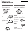
Quick Guide 28
How to Play the Drum Pads ............................... 28
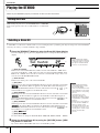
Playing the DTX900............................................. 30
Hitting the Pads.....................................................30
Selecting a Drum Kit .............................................30
Adjusting the Volume by Using the Sliders...........31
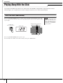
Playing Along With the Click ............................. 32
Start the Click (Metronome) ..................................32
Changing the Tempo and Time Signature
(Beat) of the Click .................................................33
Tap Tempo ........................................................... 34
Playing Along With a Song ................................ 35
Song Playback ......................................................35
Adjusting the Volume of the Song
Accompaniment ....................................................38
Changing the Tempo of the Song .........................38
Song Part Mute Setting.........................................39
Creating a Drum Kit ............................................ 40
Recording Your Drum Performance to a Song
.. 43
Recording System.................................................43
Recording Methods...............................................43
Recording Your Drum Performance to a Song .....44
Recording Additional Notes to an
Already-recorded Track (Overdub) .......................46
Recording Along With the Preset Song ................46
Re-recording a Track After Clearing .....................48
Assigning a Name to a User Song........................49
Using the Groove Check Function.....................50
Setting the Check Timing ..................................... 50
Trying Out Groove Check..................................... 51
Trying Out Rhythm Gate....................................... 52
Saving the Created Data to a USB Storage
Device ...................................................................54
File/Folder Selection............................................. 54
Saving the Created Data to a USB Storage
Device................................................................... 55
Loading a File Saved to a USB Storage Device... 56
Reference 57
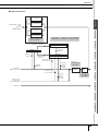
Basic Structure of the DTX900 ...........................57
The Functional Blocks .......................................... 57
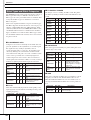
Pads (Trigger Input Sources) and
Trigger Signals ..................................................... 58
Tone Generator Block (Drum Kits and
Drum Voices)........................................................ 62
Sampling............................................................... 65
Song ..................................................................... 67
Effects................................................................... 68
Internal Memory and File Management................ 76
Drum Kit Mode [DRUM KIT] ................................78
Basic Procedure in the Drum Kit Mode ................ 78
Selecting a Drum Kit [F1] PLAY ........................... 79
Setting Drum Voice Parameters [F2] VOICE........ 79
Programming the Stack/Alternate [F3] STK/ALT.. 86
Effect Settings [F4] EFFECT ................................ 89
Pad Settings [F5] PAD.......................................... 92
Other Settings [F6] OTHER.................................. 95
Song Mode [SONG] .............................................98
Song Play [F1] PLAY............................................ 98
Song Recording [F1] PLAY
→
[REC] ................... 98
Song Jobs [F2] JOB ............................................. 98
Click Mode [CLICK] ...........................................104
Basic Procedure in the Click Mode..................... 104
Basic Settings of the Click Sound [F1] PLAY ..... 105
Click Voice Settings [F2] VOICE ........................ 106
Tap Tempo Function [F3] TAP ........................... 106
Groove Check Function [F4] GROOVE.............. 106
Click Sound Settings [F5] OTHER...................... 107
Trigger Mode [TRIGGER] ..................................108
Basic Procedure in the Trigger Mode ................. 108
Selecting the Trigger Setup [F1] SELECT.......... 109
Selecting the Pad Type [F2] TYPE..................... 109
Trigger Sensitivity Settings [F3] SENS ............... 109
Setting the Rejection [F4] REJECT .................... 110
Other Settings [F5] OTHER................................ 111

Contents
DTX900 Owner’s Manual
9
File Mode [FILE] .................................................112
Terminology in the File Mode ............................. 112
File Types Compatible With the DTX900 ........... 113
Saving a File [F1] SAVE ..................................... 114
Loading a File [F2] LOAD ................................... 116
Changing the Name of a File or Directory
[F3] RENAME ..................................................... 121
Deleting a File or Directory [F4] DELETE........... 122
Formatting USB Storage Media [F5] FORMAT .. 123
Utility Mode [UTILITY]........................................124
Basic Procedure in the Utility Mode.................... 124
General Settings [F1] GENERAL ....................... 124
Pad Settings [F2] PAD........................................ 126
Effect Settings [F3] EFFECT .............................. 127
External Audio Settings [F4] AUXIN ................... 128
MIDI Settings [F5] MIDI ...................................... 130
Resetting the User Memory to the Initial
Factory Settings [F6] FACTSET ......................... 131
Chain Mode [CHAIN]..........................................132
Using a Programmed Chain [F1] SELECT ......... 132
Programming a Chain [F2] EDIT ........................ 133
Naming the Created Chain [F3] NAME .............. 134
Sampling Mode [SAMPLING] ............................135
Sampling Setup .................................................. 135
Sampling Operation and User Voice Assignment
[F1] SELECT/[F2] SETTING............................... 136
Trimming a User Voice [F3] TRIM ...................... 139
Sampling Jobs [F4] JOB..................................... 142
Appendix 147
Optional DIMM Installation................................147
Troubleshooting.................................................150
Display Messages ..............................................153
Specifications.....................................................155
Index....................................................................156
About the Accessory Disk.................................159
SOFTWARE LICENSE AGREEMENT................159

10
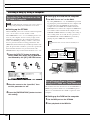
DTX900 Owner’s Manual
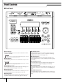
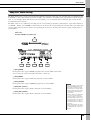
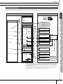
Panel Controls
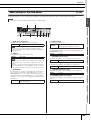
■
Front Panel
q
LCD display
The large LCD Display shows information and data needed to
operate the DTX900.
w
LED display
The LED display indicates the current Drum Kit or tempo value
in three digits.
e
[DRUM KIT] button
Pressing this button enters the Drum Kit mode, allowing you to
select the desired Drum Kit (pages 30 and 78).
r
[CLICK] button
Pressing this button enters the Click mode, allowing you to per-
form the Click (Metronome) setup (pages 32 and 104).
t
[FILE] button
Pressing this button enters the File mode, allowing you to man-
age data created in each of the modes (pages 54 and 112).
y
[CHAIN] button
Pressing this button enters the Chain mode, allowing you to
program a Chain, which is a series of Drum Kits and Songs
arranged in the order you want (page 132).
u
[SONG] button
Pressing this button enters the Song mode, allowing you to
play an existing Song or record your drum performance (pages
35 and 98).
i [TRIGGER] button
Pressing this button enters the Trigger mode, allowing you to
select or program a Trigger Setup (pages 22 and 108).
o [UTILITY] button
Pressing this button enters the Utility mode, allowing you to set
parameters related to the entire system of the DTX900 (page
124).
!0 [SAMPLING] button
Pressing this button enters the Sampling mode, allowing you to
record the external audio signal then create User Voices (page
135).
888
w
e u
r i
t o
y !0
!1
!2
!3
!6
!7 !8 !9
@0 @1 @2 @3 @4 @5
@7 @8
#0 #1
@6
@9
!4
q
!5
NOTE
• Before use, be sure to remove the transparent film applied to the LCD
display to protect it during transportation.
NOTE
• Before use, be sure to remove the transparent film applied to the LED
display to protect it during transportation.

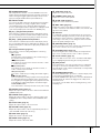
Panel Controls
DTX900 Owner’s Manual
11
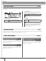
!1
TRIGGER INDICATOR
This lamp indicates whether or not the DTX900 receives the
trigger signal via the Trigger Input jacks. The lamp is turned on
when receiving the trigger signal. This lamp is turned on also
when pressing the Audition button (described below).
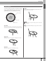
!2 Audition button
You can use this button instead of the drum pad. Pressing this
button is equivalent to receiving a signal from the currently
selected trigger input source (page 58). When turning the
power on, pressing this button is equivalent to striking the head
of the snare pad (the pad connected to the SNARE jack).
!3 [F1] – [F6] (Function) buttons
These buttons located directly below the LCD display call up
the corresponding functions indicated in the display. In the dis-
play hierarchy, these functions [F] rank just below the modes.
!4 [SF1] – [SF6] (Sub-Function) buttons
These buttons located directly below the LCD display call up
the corresponding sub functions indicated in the display. In the
display hierarchy, these sub functions [SF] rank just below the
functions [F].
!5 Transport buttons (page 35)
These buttons control recording and playback of the Song
sequence data.
pp
pp
(Top) button
Instantly returns to the beginning of the current Song (i.e.,
the first beat of the first measure).
rr
rr
(Reverse) button
Press briefly to move back one measure at a time, or hold
to continuously rewind.
ff
ff
(Forward) button
Press briefly to move forward one measure at a time, or
hold to continuously fast-forward.
REC (Record) button
Press this to enable Song recording. (The indicator lights.)
>>
>>
/■ (Play/Stop) button
Press to start/stop recording or playback. Pressing this but-
ton during playback stops playback at the current point in
the Song then pressing this again starts playback from that
point. During recording and playback, the indicator lights.
CLICK ON/OFF button
Press this button to start/stop the metronome (click sound).
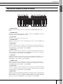
!6 MASTER slider (page 31)
Adjusts the output volume of the stereo mix from the OUTPUT
L/MONO and R jacks.
!7 PHONES slider (page 31)
Adjusts the output volume of the stereo-mixed sounds for the
PHONES jack. This is independent from the MASTER slider
setting.
!8 CLICK slider (page 31)
Adjusts the output volume of the click sound.
!9 ACCOMP slider (page 31)
Adjusts the output volume of the accompaniment parts (those
other than MIDI channel 10) in the Song.
@0 KICK slider (page 31)
Adjusts the volume of the bass drum.
@1 SNARE slider (page 31)
Adjusts the volume of the snare drum.
@2 TOM slider (page 31)
Adjusts the volume of the toms.
@3 CYMBAL slider (page 31)
Adjusts the volume of the cymbals.
@4 HI-HAT slider (page 31)
Adjusts the volume of the hi-hat cymbals.
@5 MISC slider (page 31)
Adjusts the volume of miscellaneous rhythm or percussion
sounds – other than snare and bass drums, toms, hi-hats, and
ride and crash cymbals.
@6 Data dial
For editing the currently selected parameter. To increase the
value, turn the dial right (clockwise); to decrease the value, turn
the dial left (counter-clockwise). If a parameter with a wide
value range is selected, you can change the value in broader
strokes by quickly turning the dial.
@7 [DEC/NO] button (page 13)
For decreasing the value of the currently selected parameter.
Also use it to cancel a Job or a Store operation.
@8 [INC/YES] button (page 13)
For increasing the value of the currently selected parameter.
Also use it to actually execute a Job or a Store operation.
@9 Cursor buttons (page 13)
The cursor buttons move the “cursor” around the LCD display
screen, highlighting and selecting the various parameters.
#0 [EXIT] button
Press this button to cancel an operation when a confirmation
message is shown in the LCD. This button can be used also
when the drum sound continues inadvertently or unexpectedly
and you want to stop it.
#1 [ENTER/STORE] button
As with the ENTER button, press this to enter the display of the
selected Song Job/Sampling Job, for example.
As with the STORE button, press this to store the edited data in
the Drum Kit mode, Click mode, Trigger mode, Utility mode,
and Chain mode.
You can also use this button when executing the Song Job or
Sampling Job.

Panel Controls
12
DTX900 Owner’s Manual
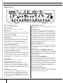
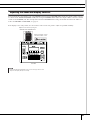
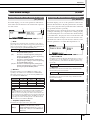
■ Rear Panel
q F (Standby/On) switch
Press to turn the power ON or OFF.
w DC IN terminal
Connect the AC power adaptor to this terminal.
e Cable clip
Wrap the DC output cable of the adaptor around the cable clip
to prevent accidental unplugging of the cable during operation.
r LCD Contrast Control
Use this control to set the LCD display for optimum legibility.
t GAIN knob
For adjusting the input gain of the audio at the AUX IN/SAM-
PLING IN jack. Depending on the connected device (micro-
phone, CD player, etc.), you may need to adjust this for
optimum level. Increase the gain by rotating the knob clock-
wise, and decrease it by rotating the knob counter-clockwise.
y AUX IN/SAMPLING IN jack
External audio signals can be input via this phone jack (stan-
dard stereo phone plug). This is convenient for playing along
with music from a CD player or other device. In the Sampling
mode, this jack is used for capturing audio data as User Voices.
u OUTPUT L/MONO and R jacks
External audio signals can be input via these phone jacks (1/4"
mono phone plug). Various devices such as microphone, gui-
tar, bass, CD player, can be connected to these jacks. For ste-
reo signals (such as from audio equipment), use both jacks.
For mono signals (such as from a microphone or guitar), use
only the L jack.
i PHONES jack
For connection to a pair of stereo headphones.
o INDIVIDUAL OUTPUT 1 – 6 jacks
Line level audio signals are output from this instrument via
these phone jacks (1/4" mono phone plug). These outputs are
independent of the main output (at the L/MONO and R jacks),
and can be freely assigned to any Drum Voice. This lets you
route specific sounds for processing with a favorite outboard
effect unit.
!0 DIGITAL OUT connector
This is for connecting to a coaxial digital input (S/P DIF) on an
external audio device. This jack digitally outputs stereo audio
signals identical to those from the OUTPUT L/MONO and R
jacks, but is not affected by the !6 MASTER volume slider set-
ting (the digital jack always outputs audio signals at the maxi-
mum volume level).
!1 MIDI IN/OUT connectors
These jacks are for the transfer of MIDI data to and from exter-
nal MIDI devices.
!2 USB terminals
This instrument is equipped with two types of USB terminals on
the rear panel – USB TO HOST and USB TO DEVICE. The
USB TO HOST terminal is used to connect this instrument to
the computer via the USB cable. The USB connection between
the instrument and the computer can only be used for transfer
of MIDI data. No audio data can be transferred via USB. The
USB TO DEVICE terminal is used to connect this instrument to
a USB storage device (flash memory, hard disk drive, etc.) via
the USB cable. This lets you save the data created on this
instrument to an external USB storage device as well as load
data from the device to the instrument. Save/Load operations
can be performed in the File mode.
!3 HI-HAT CONTROL jack
This jack is used to connect a hi-hat controller. Depending on
the setting on the Drum Kit mode (page 78), you can transmit
the MIDI messages such as Control Change by using the Hi-
Hat Controller.
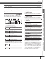
!4 Trigger Input jacks (q SNARE – o HI-HAT)
These jacks, which are compatible with stereo pads (two-zone
and three-zone pads) as well as mono pads, receive the Trigger
Signal transmitted from the drum pads. Furthermore, the q
SNARE – t TOM4 jacks are also compatible with the Pad
Controller (page 59).
!5 Trigger Input jack (!0/!1 KICK)
This jack is designed to accept two separate trigger signals
from two mono (single) pad by using a Y-shaped cable (stereo
phone plug for this jack and two mono plugs for the two pads).
When using the KP125W/KP65 equipped with the PAD INPUT
jack, the Trigger Signals of another pad connected to the PAD
INPUT jack and KP itself can be transferred via a single stereo
cable (no need for a Y-shaped cable) to the DTX900. In this
case, the stereo cable is plugged into the OUTPUT jack of a
pad and this Trigger Input jack.
!6 Trigger Input jacks (!2 – !5)
These jacks, which are compatible with stereo pads (two-zone
and three-zone pads) as well as mono pads, receive the Trigger
Signal transmitted from the drum pads.
wq
e
t
y
u
i
r
o
!0
!1
!2
!5
!3
!6 !4

DTX900 Owner’s Manual
13
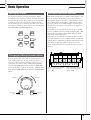
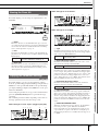
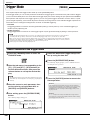
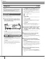
Basic Operation
Use these four buttons to navigate through the display,
moving the cursor around the various selectable items and
parameters in the screen. When selected, the relevant item
is highlighted (the cursor appears as a dark block with
inverse characters). You can change the value of the item
(parameter) at which the cursor is located by using the data
dial, [INC/YES] and [DEC/NO] buttons.
Rotating the data dial to the right (clockwise) increases the
value, while rotating it to the left (counter-clockwise)
decreases it. For parameters with large value ranges, you
can increase the value by 10 by simultaneously holding
down the [INC/YES] button and pressing the [DEC/NO]
button. To decrease by 10, do the opposite; simultaneously
hold down the [DEC/NO] button and press the [INC/YES]
button.
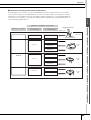
Each mode described above contains various displays, with
various functions and parameters. To navigate your way
through these displays and select a desired function, use the
[F1] – [F6] buttons and the [SF1] – [SF6] buttons. When
you select a mode, the available displays or menus appear
directly above the buttons at the bottom of the display (as
shown below).
Depending on the currently selected mode, up to six func-
tions are available and can be called up with the [F1] – [F6]
buttons. Keep in mind that the available functions differ
depending on the selected mode.
Depending on the currently selected mode, up to six func-
tions (sub-functions) are also available and can be called up
with the [SF1] – [SF6] buttons. Keep in mind that the avail-
able functions differ depending on the selected mode.
(Some displays may not have any sub-functions for these
buttons.)
Moving the Cursor
Changing or Editing Parameter Values
IncreaseDecrease
Increase
by 1
Decrease
by 1
Functions and Sub-Functions
These functions can be selected
via the corresponding button
([F1] – [F6]).
These functions can be selected
via the corresponding button
([SF1] – [SF6]).

Basic Operation
14
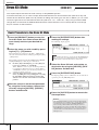
DTX900 Owner’s Manual
In order to make operation of the DTX900 as comprehen-
sive and as smooth as possible, all functions and operations
have been grouped in “modes.” To enter the desired mode,
press the corresponding Mode button.
The function of each mode is as follows:
You can adjust or set various parameters by using the data
dial, [INC/YES] button and [DEC/NO] button in each
mode. When changing the value of the parameter in these
modes, the [E] (Edit Indicator) will appear on the top left
corner of the LCD display. This indicates that the current
program (Drum Kit, etc.) has been modified but not yet
stored. If you wish to store the status or sound obtained by
editing, be sure to store the current program to internal
User memory by pressing the [ENTER/STORE] button
before selecting another program.
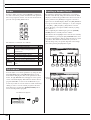
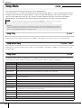
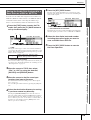
For parameters having large value ranges, you can also
enter the value directly, using the buttons below the LCD
display as a numeric keypad. When the cursor is located on
such a parameter, the [NUM] icon appears at the lower
right corner of the LCD display. When the [SF6] NUM but-
ton is pressed in this status, each digit (1 – 9, 0) is assigned
to the [SF1] – [SF5] and [F1] – [F5] buttons as shown
below, allowing you to input a number directly by using
these buttons.
After completing the number input, press the [ENTER/
STORE] button to actually enter the number.
Note that the cursor highlight can be moved to the currently
edited number by pressing the [F6] CURSOR button, and
then moved from digit to digit by using the Cursor [N] and
[M] buttons. This method is useful when you want to
directly change only one specific digit. The cursor disap-
pears when pressing the [F6] button again.
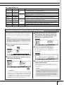
Modes
Mode Function Page
Drum Kit Selecting/editing a Drum Kit. 78
Click
Setting the Click (Metronome) related
parameters and performing the Groove
Check function.
104
File Managing files and directories (folders). 112
Chain Programming a Chain sequence. 132
Song Selecting/recording a Song. 98
Tr igger Selecting/editing a Trigger Setup. 108
Utility Setting the system related parameters. 124
Sampling
Recording audio signals to create a User
Voice.
135
Edit Indicator
If the Edit Indicator appears...
Inputting a Number Directly
Numeric
Keypad

Basic Operation
DTX900 Owner’s Manual
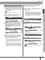
15
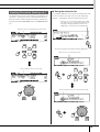
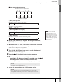
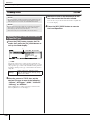
As shown below, you can set the name by repeating the two
operations – moving the cursor to the desired location by
using the Cursor buttons and then selecting a character by
using the data dial, [INC/YES] button, and [DEC/NO] but-
ton.
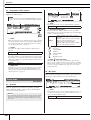
■ Using the character list
If you find it difficult to select the desired characters with
the above method, you may want to use the following
method – selecting the characters directly from a list.
Inputting Characters (Naming, etc.)
Move the cursor to the desired location in the name
Select a character at the cursor location
When the cursor is located at the Name, this [LIST]
icon appears and you can call up the Character List
display by holding the [SF6] button. Release the
[SF6] button to return back to the original display.
Perform the operations below while holding the [SF6] button.
Move the cursor to the desired location.
Select a character for the cursor location in the name.

16
DTX900 Owner’s Manual
Setting Up
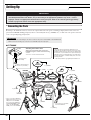
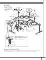
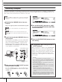
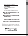
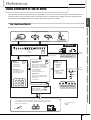
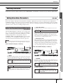
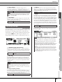
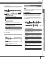
Connecting the Pads
Referring to the illustration below, connect the output cable from each pad to each Trigger Input jack located on the rear
panel of the DTX900. All Trigger Input jacks are conveniently labeled (1 SNARE, etc.), so make sure each pad is connected
to its corresponding Trigger Input jack.
■ DTX900K
IMPORTANT
You’ll need to change the Trigger Settings of the DTX900 according to the type of drum set you are using (Stan-
dard Set/Special Set/Acoustic Drums, etc.). If the setting is not appropriate, problems may occur—such as
improper sound, or inappropriate volume balance among the pads. Refer to the “Selecting the Trigger Setup”
section on page 22 on how to select the appropriate setup.
•To prevent electric shock and damage to the devices, make sure the power is switched OFF on the DTX900 and all
related devices before making any connections to the DTX900’s input and output jacks.
WARNING
PCY135
DTX900
PCY155
PCY135
KP125W
XP120SD
RHH135
XP100T XP100T
XP100T
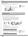
Attaching the module stand
Attach the included module stand to the
DTX900 using the module stand fastening
screws.
* Be sure to use the included screws.
to 1SNARE
to JKICK/K
to 2TOM1 to 3TOM2
to 4TOM3
to HI-HAT
CONTROL
to 9HI-HAT
to 7CRASH
to 6RIDE
DTX900
Module stand
(included)
Module stand fastening
screws x 4 (included)
* First, connect the RHH135’s
[PAD] output jack to the 9HI-
HAT jack on the DTX900,
then connect the RHH135’s
[HI-HAT CONTROL] output
jack to the HI-HAT CON-
TROL jack on the DTX900.
*Foot pedal is not included
in the Standard Set.
NOTE
• The pad models described in the illustrations were
included in the Standard Set/Special Set at the moment
this Owner’s Manual was produced. Keep in mind that the
model names of your Standard Set or Special Set may be
different from the ones illustrated here. For details about
the latest information on Yamaha drum pads, refer to the
following website.
http://www.yamaha.co.jp/english/product/drums/ed/
to 8CRASH2

Setting Up
DTX900 Owner’s Manual
17
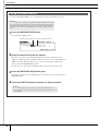
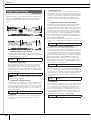
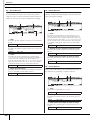
■ DTX950K
■ Setting up with Acoustic Drums
The DTX900 can be played from an acoustic drum kit if the kit is fitted with an optional set of drum triggers (such as
Yamaha DT20 Drum Triggers) and the triggers are properly connected to the input jacks of the DTX900.
PCY135
PCY135
DTX900
PCY155
KP125W
XP120SD
RHH135
XP100T XP100T
XP120T
XP120T
Attaching the module stand
Attach the included module stand to the
DTX900 using the module stand fastening
screws.
* Be sure to use the included screws.
DTX900
Module stand
(included)
Module stand fastening
screws x 4 (included)
to 1SNARE
to JKICK/K
*Foot pedal is not included
in the Special Set.
to 9HI-HAT
to HI-HAT
CONTROL
to 7CRASH1
to 2TOM1 to 3TOM2
to 5TOM4
to 4TOM3
to 6RIDE
to 8CRASH2
* First, connect the RHH135’s
[PAD] output jack to the 9HI-
HAT jack on the DTX900, then
connect the RHH135’s [HI-HAT
CONTROL] output jack to the
HI-HAT CONTROL jack on the
DTX900.

Setting Up
18
DTX900 Owner’s Manual
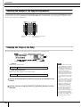
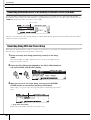
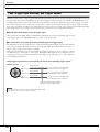
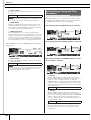
Setting Up the Power Supply
1
Make sure that the F (Standby/On) switch
of the instrument is set to standby ( ).
2
Connect the DC plug of the included AC
power adaptor to the DC IN jack on the
rear panel. To prevent the cord from being
unplugged accidentally, wrap the cord
around the cable clip and secure it.
3
Connect the other end of the power cord
to an AC outlet.
Turning the Power On
After you’ve made all necessary connections (trigger,
audio, MIDI), turn down all volume controls of the
DTX900 and other audio equipment.
Turn the power on ( ) by pressing the F (Standby/On)
switch on the rear panel of the DTX900, then turn on the
power of the amplifiers.
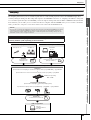
■ Connecting a mixer or other MIDI
devices
Make sure that all volume settings are turned down all the
way to the minimum. Then turn on the every device in your
setup in the order of MIDI masters (controllers), MIDI
slaves (receivers), then audio equipment (mixers, amplifi-
ers, speakers, etc.).
• Make sure that the power adaptor’s cord is not bent at an extreme
angle when wrapping the cord around the clip. Doing this can dam-
age or sever the cord and create a fire hazard.
• Use only the included power adaptor or an equivalent recom-
mended by Yamaha. The use of any other adaptors may cause
irregular operation or damage to the device.
• Only use the voltage specified as correct for the DTX900.
•Even when the instrument is turned off, electricity is still flowing to
the instrument at the minimum level. When you are not using the
DTX900 for a long time, make sure to unplug the AC power adap-
tor from the wall AC outlet.
CAUTION
WARNING
NOTE
• When powering down the setup, first turn down the volume for each audio
devices, then switch off each device in the reverse order (first audio equip-
ment, then MIDI).
888
1 DTX900
(transmitting device)
2 MIDI slave
3 External audio equipment
(mixer → amplifier)

Setting Up
DTX900 Owner’s Manual
19
Connecting to Speakers or
Headphones
Since the DTX900 has no built-in speakers, you’ll need an
external audio system or a set of stereo headphones to
properly monitor it.
■ OUTPUT L/MONO, R jacks (standard
mono phone)
These jacks allow you to connect the DTX900 to an exter-
nal amplifier/speaker system and produce full, amplified
sound.
• Use the DTX900’s OUTPUT L/MONO jack when
connecting to a device with a mono input.
■ PHONES jack (standard stereo phone
jack)
The overall headphone level is adjusted by the PHONES
slider.
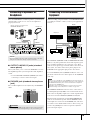
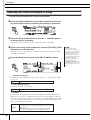
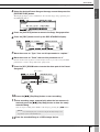
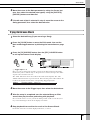
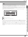
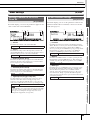
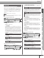
Connecting to External Audio
Equipment
When recording your performance on a DTX900 Drum Kit
or sending its sounds to a mixer, connect your equipment as
follows:
The OUTPUT (L/MONO and R) and INDIVIDUAL OUT-
PUT (1 to 6) jacks produce line level audio signals regard-
less of whether headphones are connected or not. These
jacks are mono phone type. To make audio connections via
these jacks, use cables with a mono phone plug for the
DTX900 and an appropriate plug for the other device.
Use both OUTPUT jacks (L/MONO and R) for stereo out-
put. If the other device has a mono input, use the L/MONO
jack only.
The DIGITAL OUTPUT connector can be connected to a
coaxial digital input (S/P DIF) on an external audio device.
This connector digitally outputs stereo audio signals identi-
cal to those from the OUTPUT L/MONO and R jacks.
External audio signals input to AUX IN/SAMPLING IN
jack can be monitored together with the DTX900 sounds
via headphones connected to the PHONES jack, and can be
recorded to create additional User Voices. If necessary, you
can use the [GAIN] knob on the rear panel to adjust the
gain of the input signal.
• Whenever making connections, make sure that the plug on the cable
being used corresponds to the type of jack on the device.
• Do not use the DTX900 at a high volume level for a long period of time,
or your hearing may be damaged. Doing so may cause hearing loss.
Headphones
Monitor system for the DTX series
MS100DR, MS50DR, etc.
OUTPUT L/MONO, R
PHONES
NOTICE
CAUTION
NOTE
• Connect a set of headphones to the PHONES jack for monitoring the ste-
reo output (identical to that of the OUTPUT jacks). The sounds output from
the INDIVIDUAL OUTPUT jacks cannot be heard from the headphones
connected to the PHONES jack.
• Depending on the connected equipment, you may need to change the
parameter settings in the Utility mode. For details, see page 128.
INDIVIDUAL
OUTPUT
DIGITAL OUT
DIGITAL IN
AUX OUT
LINE OUT
AUX IN
O1V96
SOLO SOLO
ON ON
SOLO
ON
SOLO
ON
SOLO
ON
SOLO
ON
SOLO
ON
SOLO
ON
SOLO
ON
SOLO
ON
SOLO
ON
SOLO
ON
SOLO
ON
SOLO
ON
SOLO
ON
SOLO
ON
SOLO
ON
SOLO
ONON
PEAK
SIGNAL
PEAK
SIGNAL
PEAK
SIGNAL
PEAK
SIGNAL
PEAK
SIGNAL
PEAK
SIGNAL
PEAK
SIGNAL
PEAK
SIGNAL
PEAK
SIGNAL
PEAK
SIGNAL
PEAK
SIGNAL
PEAK
SIGNAL
PEAK
SIGNAL
PEAK
SIGNAL
1-16 17-32 MASTER REMOTE
LAYER
SEL SEL SEL SEL SEL SEL SEL SEL SEL SEL SEL SEL SEL SEL SEL SEL SEL SELSEL
ST IN
ENTER
EQUALIZER
HIGH
HIGH-MID
LOW-MID
LOW
Q
FREQUENCY
GAIN
STEREO
SELECTED CHANNEL
PAN
DEC INC
SOLO CLEAR
RECALL
STORE
SCENE MEMORY
PHONES
MONITOR
OUT
MONITOR
2TR IN
CH15
/
16
2TR IN
LEVEL
PHONES
LEVEL
0
10
0
10
+4
-26
GAIN
+4
-26
GAIN
+4
-26
GAIN
GAIN
+4
-26
GAIN
20dB
-16 -60
GAIN
20dB
-16 -60
GAIN
20dB20dB20dB20dB20dB20dB20dB20dB20dB20dB
-16 -60
GAIN
-16 -60
GAIN
-16 -60
GAIN
-16 -60
GAIN
-16 -60
GAIN
-16 -60
GAIN
-16 -60
GAIN
-16 -60
GAIN
-16 -60
GAIN
-16 -60
PAD
FADER MODE
DISPLAY ACCESS
AUX 1
AUX 1 AUX 2 AUX 3 AUX 4 AUX 5 AUX 6 AUX 7 AUX 8 BUS 1 BUS 2 BUS 3 BUS 4 BUS 5 BUS 6 BUS 7 BUS 8
AUX 2 AUX 3 AUX 4
AUX 8AUX 7AUX 6AUX 5
HOME (METER)
DYNAMICS
EQ EFFECT VIEW
PATCH
UTILITYMIDISCENE
DIO/SETUP
/ INSERT/
DELAY
PAN/
ROUTING
PAIR/
GROUP
A
B
A
B
A
B
A
B
A
B
A
B
A
B
A
B
A
B
A
B
A
B
A
B
16
1513
121110987643215
14
INSERT I
/
OINSERT I
/
OINSERT I
/
OINSERT I
/
OINSERT I
/
OINSERT I
/
OINSERT I
/
OINSERT I
/
OINSERT I
/
OINSERT I
/
OINSERT I
/
OINSERT I
/
O
L
R
IN OUT
2TR
-10dBV (UNBAL)
PHANTOM +48V
CH9-12CH5-8CH1-4
INPUT
(BAL)
INSERT
OUTIN
(UNBAL)
ST IN 1 ST IN 2
USER DEFINED
KEYS
12
34
56
78
55
5
+10
5
1010
10
1515
15
2020
20
303030
30
4040
40
5050
50
6060
7070
20
30
40
40
50
50
60
70
00
5
10
15
20
0
0
5
+10
5
10
15
30
20
30
40
40
50
50
60
70
20
30
40
40
50
50
60
70
20
30
40
40
50
50
60
70
20
30
40
40
50
50
60
70
20
30
40
40
50
50
60
70
15
0
5
10
15
20
0
5
+10
5
10
0
30
15
5
10
15
20
0
5
+10
5
10
0
30
15
5
10
15
20
0
5
+10
5
10
0
30
15
5
10
15
20
0
5
+10
5
10
0
30
15
20
30
40
40
50
50
60
70
30
15
20
30
40
40
20
30
40
20
30
40
20
30
40
50
50505050
20
30
40
50
20
30
40
50
60
70
40
50
60
70
40
50
60
70
40
50
60
70
40
50
60
70
40
50
60
70
40
50
60
70
40
50
60
70
30
15
5
10
15
20
0
5
+10
5
10
0
5
10
15
20
0
5
+10
5
10
0
5
10
15
20
0
30
5
10
15
20
0
30
5
10
15
20
0
30
5
10
15
20
0
30
5
10
15
20
0
303030
5
10
15
20
0
5
10
15
20
0
5
10
15
20
0
5
+10
5
10
0
15
5
+10
5
10
0
15
5
+10
5
10
0
15
5
+10
5
10
0
15
20
30
40
50
15 15
20
30
40
50
15
5
+10
5
10
0
5
+10
5
10
0
5
+10
5
10
0
5
+10
5
10
0
123456
123456
7
891011 12
7
891011 12
13 14 15 16
13 14 15 16
32313029282726252423222120191817
STEREO
13 14 15 16
OVER
0
-3
-6
-9
-12
-15
-18
-24
-30
-36
-48
888
CD player
MD player
DTX900

Setting Up
20
DTX900 Owner’s Manual
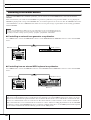
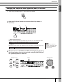
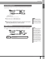
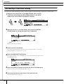
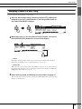
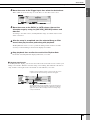
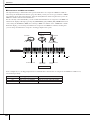
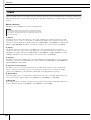
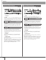
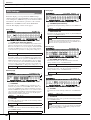
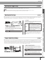
Connecting External MIDI Devices
Using a standard MIDI cable (available separately), you can connect an external MIDI device, and control it from the
DTX900.
This connection lets you sound an external MIDI tone generator (synthesizer, tone generator module, etc.) by playing the
DTX900 or playing back a Song on the DTX900. Also, an external sequencer can be used to drive the DTX900’s Tone Gen-
erator. Furthermore, the use of MIDI functions allows for an even greater range of performance and recording possibilities
with the DTX900.
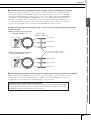
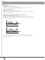
■ Controlling an external tone generator or synthesizer
Use a MIDI cable to connect the MIDI OUT connector on the DTX900 with the MIDI IN connector on the external MIDI
device.
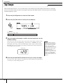
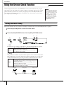
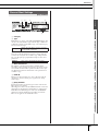
■ Controlling from an external MIDI keyboard or synthesizer
Use a MIDI cable to connect the MIDI IN connector on the DTX900 with the MIDI OUT connector on the external MIDI
device.
NOTE
•Any one of the DTX900 interfaces (MIDI connectors or the USB terminal) can be used for MIDI data transmission/
reception. However, they cannot be used at the same time. Select which connector is used for MIDI data transfer in
the Utility mode with the following operation: [UTILITY] → [F5] MIDI → [SF3] OTHER → MIDI IN/OUT
888
DTX900
MIDI device
MIDI IN connector
MIDI OUT connector
MIDI cable
888
DTX900
MIDI device
MIDI OUT connector
MIDI IN connector
MIDI cable
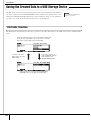
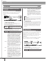
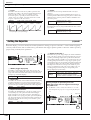
Synchronizing with an external MIDI instrument (Master and Slave)
The Songs of this instrument can be synchronized to the playback of an external MIDI sequencer, To do this, one device
must be set to internal clock operation and the other (as well as all other devices to be controlled) to external clock. The
device set to internal clock serves as a reference for all connected devices, and is referred to as the “master” instrument.
The connected devices set to external clock are referred to as “slaves.” When recording playback data of an external MIDI
sequencer to a Song of the DTX900 in the above connection example, make sure to set the MIDI synchronization param-
eter to follow external clock with the following operation in the Utility mode.
Seite wird geladen ...
Seite wird geladen ...
Seite wird geladen ...
Seite wird geladen ...
Seite wird geladen ...
Seite wird geladen ...
Seite wird geladen ...
Seite wird geladen ...
Seite wird geladen ...
Seite wird geladen ...
Seite wird geladen ...
Seite wird geladen ...
Seite wird geladen ...
Seite wird geladen ...
Seite wird geladen ...
Seite wird geladen ...
Seite wird geladen ...
Seite wird geladen ...
Seite wird geladen ...
Seite wird geladen ...
Seite wird geladen ...
Seite wird geladen ...
Seite wird geladen ...
Seite wird geladen ...
Seite wird geladen ...
Seite wird geladen ...
Seite wird geladen ...
Seite wird geladen ...
Seite wird geladen ...
Seite wird geladen ...
Seite wird geladen ...
Seite wird geladen ...
Seite wird geladen ...
Seite wird geladen ...
Seite wird geladen ...
Seite wird geladen ...
Seite wird geladen ...
Seite wird geladen ...
Seite wird geladen ...
Seite wird geladen ...
Seite wird geladen ...
Seite wird geladen ...
Seite wird geladen ...
Seite wird geladen ...
Seite wird geladen ...
Seite wird geladen ...
Seite wird geladen ...
Seite wird geladen ...
Seite wird geladen ...
Seite wird geladen ...
Seite wird geladen ...
Seite wird geladen ...
Seite wird geladen ...
Seite wird geladen ...
Seite wird geladen ...
Seite wird geladen ...
Seite wird geladen ...
Seite wird geladen ...
Seite wird geladen ...
Seite wird geladen ...
Seite wird geladen ...
Seite wird geladen ...
Seite wird geladen ...
Seite wird geladen ...
Seite wird geladen ...
Seite wird geladen ...
Seite wird geladen ...
Seite wird geladen ...
Seite wird geladen ...
Seite wird geladen ...
Seite wird geladen ...
Seite wird geladen ...
Seite wird geladen ...
Seite wird geladen ...
Seite wird geladen ...
Seite wird geladen ...
Seite wird geladen ...
Seite wird geladen ...
Seite wird geladen ...
Seite wird geladen ...
Seite wird geladen ...
Seite wird geladen ...
Seite wird geladen ...
Seite wird geladen ...
Seite wird geladen ...
Seite wird geladen ...
Seite wird geladen ...
Seite wird geladen ...
Seite wird geladen ...
Seite wird geladen ...
Seite wird geladen ...
Seite wird geladen ...
Seite wird geladen ...
Seite wird geladen ...
Seite wird geladen ...
Seite wird geladen ...
Seite wird geladen ...
Seite wird geladen ...
Seite wird geladen ...
Seite wird geladen ...
Seite wird geladen ...
Seite wird geladen ...
Seite wird geladen ...
Seite wird geladen ...
Seite wird geladen ...
Seite wird geladen ...
Seite wird geladen ...
Seite wird geladen ...
Seite wird geladen ...
Seite wird geladen ...
Seite wird geladen ...
Seite wird geladen ...
Seite wird geladen ...
Seite wird geladen ...
Seite wird geladen ...
Seite wird geladen ...
Seite wird geladen ...
Seite wird geladen ...
Seite wird geladen ...
Seite wird geladen ...
Seite wird geladen ...
Seite wird geladen ...
Seite wird geladen ...
Seite wird geladen ...
Seite wird geladen ...
Seite wird geladen ...
Seite wird geladen ...
Seite wird geladen ...
Seite wird geladen ...
Seite wird geladen ...
Seite wird geladen ...
Seite wird geladen ...
Seite wird geladen ...
Seite wird geladen ...
Seite wird geladen ...
Seite wird geladen ...
Seite wird geladen ...
Seite wird geladen ...
Seite wird geladen ...
Seite wird geladen ...
-
 1
1
-
 2
2
-
 3
3
-
 4
4
-
 5
5
-
 6
6
-
 7
7
-
 8
8
-
 9
9
-
 10
10
-
 11
11
-
 12
12
-
 13
13
-
 14
14
-
 15
15
-
 16
16
-
 17
17
-
 18
18
-
 19
19
-
 20
20
-
 21
21
-
 22
22
-
 23
23
-
 24
24
-
 25
25
-
 26
26
-
 27
27
-
 28
28
-
 29
29
-
 30
30
-
 31
31
-
 32
32
-
 33
33
-
 34
34
-
 35
35
-
 36
36
-
 37
37
-
 38
38
-
 39
39
-
 40
40
-
 41
41
-
 42
42
-
 43
43
-
 44
44
-
 45
45
-
 46
46
-
 47
47
-
 48
48
-
 49
49
-
 50
50
-
 51
51
-
 52
52
-
 53
53
-
 54
54
-
 55
55
-
 56
56
-
 57
57
-
 58
58
-
 59
59
-
 60
60
-
 61
61
-
 62
62
-
 63
63
-
 64
64
-
 65
65
-
 66
66
-
 67
67
-
 68
68
-
 69
69
-
 70
70
-
 71
71
-
 72
72
-
 73
73
-
 74
74
-
 75
75
-
 76
76
-
 77
77
-
 78
78
-
 79
79
-
 80
80
-
 81
81
-
 82
82
-
 83
83
-
 84
84
-
 85
85
-
 86
86
-
 87
87
-
 88
88
-
 89
89
-
 90
90
-
 91
91
-
 92
92
-
 93
93
-
 94
94
-
 95
95
-
 96
96
-
 97
97
-
 98
98
-
 99
99
-
 100
100
-
 101
101
-
 102
102
-
 103
103
-
 104
104
-
 105
105
-
 106
106
-
 107
107
-
 108
108
-
 109
109
-
 110
110
-
 111
111
-
 112
112
-
 113
113
-
 114
114
-
 115
115
-
 116
116
-
 117
117
-
 118
118
-
 119
119
-
 120
120
-
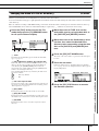 121
121
-
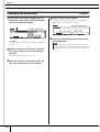 122
122
-
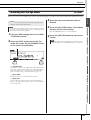 123
123
-
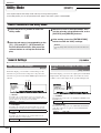 124
124
-
 125
125
-
 126
126
-
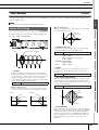 127
127
-
 128
128
-
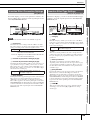 129
129
-
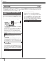 130
130
-
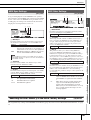 131
131
-
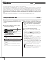 132
132
-
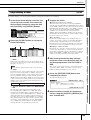 133
133
-
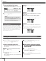 134
134
-
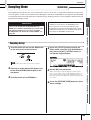 135
135
-
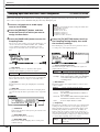 136
136
-
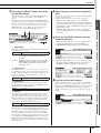 137
137
-
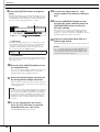 138
138
-
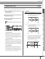 139
139
-
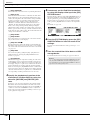 140
140
-
 141
141
-
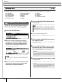 142
142
-
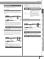 143
143
-
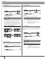 144
144
-
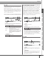 145
145
-
 146
146
-
 147
147
-
 148
148
-
 149
149
-
 150
150
-
 151
151
-
 152
152
-
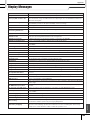 153
153
-
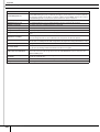 154
154
-
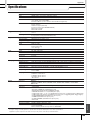 155
155
-
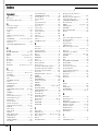 156
156
-
 157
157
-
 158
158
-
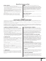 159
159
-
 160
160


Yamaha DTX-900 Bedienungsanleitung
- Kategorie
- Musikinstrumente
- Typ
- Bedienungsanleitung
- Dieses Handbuch eignet sich auch für
in anderen Sprachen
- English: Yamaha DTX-900 Owner's manual
- français: Yamaha DTX-900 Le manuel du propriétaire
- español: Yamaha DTX-900 El manual del propietario
- italiano: Yamaha DTX-900 Manuale del proprietario
- русский: Yamaha DTX-900 Инструкция по применению
- Nederlands: Yamaha DTX-900 de handleiding
- português: Yamaha DTX-900 Manual do proprietário
- dansk: Yamaha DTX-900 Brugervejledning
- polski: Yamaha DTX-900 Instrukcja obsługi
- čeština: Yamaha DTX-900 Návod k obsluze
- svenska: Yamaha DTX-900 Bruksanvisning
- Türkçe: Yamaha DTX-900 El kitabı
- română: Yamaha DTX-900 Manualul proprietarului
Verwandte Artikel
-
Yamaha DTX450K Bedienungsanleitung
-
Yamaha PSR-S670 Installationsanleitung
-
-
Yamaha FGDP-50 Benutzerhandbuch
-
-
-
-
Yamaha DTX900M Bedienungsanleitung
-
-
Andere Dokumente
-
Roland HD-3 Benutzerhandbuch
-
Fender G-DEC 30 Benutzerhandbuch
-
Alesis SampleRack Benutzerhandbuch
-
Asus SamplePad Pro Eight Pad Sample Playback Percussion Instrument Benutzerhandbuch
-
-
Steinberg Geoove Agent Bedienungsanleitung
-
Ashdown Engineering MF 484 2.N Benutzerhandbuch
-
Zeck Audio TWISTERMIX Bedienungsanleitung
-
Alesis Performance Pad Pro Benutzerhandbuch