CARLO GAVAZZI UA 30 CLD Benutzerhandbuch
- Kategorie
- Komfortbeleuchtung
- Typ
- Benutzerhandbuch
Dieses Handbuch ist auch geeignet für

User Manual
Bedienungsanleitung
Manuel de l’utilisateur
Manual del Usuario
Manuale d’istruzione
Brugerhåndbog
Ultrasonic
Ultraschall / Détecteurs ultrasoniques /
Ultrasonidos / Sensori ad ultrasuoni / Ultrasonisk
Diffuse, Programmable Outputs
Abstandssensor, programmierbare Ausgänge /
Réflexion directe objet, sorties programmables /
Detección directa, salidas programables /
Sensori a riflessione, uscite programmabili /
Diffuse, programmerbare udgange

ENGLISHDEUTSCHFRANÇAISESPAÑOLITALIANODANSK
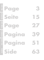
Page 3
Seite 15
Page 27
Pagina 39
Pagina 51
Side 63

3
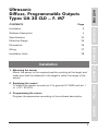
Ultrasonic
Diffuse, Programmable Outputs
Types UA 30 CLD .. F. M7
CONTENTS Page
Installation 3
Software Description 4
Specifications 74
Detection Range 76
Dimensions 76
Wiring 77
Installation Hints 78
ENGLISH
FRANÇAIS
ESPAÑOL
ITALIANO
DANSK DEUTSCH
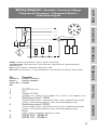
1. Mounting the sensor
Mount the sensor in the required position pointing at the target and
make sure that the distance to the target is within the range of the
sensor.
2. Supplying the sensor
To supply the sensor connect pin 2 to ground (0 V GND) and pin 1
to + (19 - 30 VDC).
3. Programming the sensor
Program the parametres according to the software description.
Installation

4
ENGLISHDEUTSCHFRANÇAISESPAÑOLITALIANODANSK
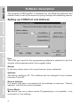
Software Description
The program UDSProg.EXE is designed for the Windows platform and
makes it easy to set up the sensor by going through self-explaining menus.
Setting up COM Port and Address
Port
The COM port used for the programming adapter is selected in the first
window which appears when the program starts.
Sensor
In the drop-down menu, the correct sensor type is selected.
Address
The factory setting is 97. The address can be changed to any number
between 0 and 99.
Search address
If a sensor has been connected and the address is unknown, “Search
address” will find the correct address.
Demo-Mode
The sensor can run in demo-mode. Programming is not possible - only
verification of the settings.

5
ENGLISH
FRANÇAIS
ESPAÑOL
ITALIANO
DANSK DEUTSCH
Initialize sensor
The sensor is reset to factory settings.
Ok
The settings are confirmed, and the main menu appears.
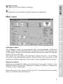
Main menu
Analogue output
The analogue output is programmed with two parameters, offset and
range. Offset is the distance from the sensor front to the closest end
of the range. Range is the distance which causes the output to change
from 0-10 V or 4-20 mA.
The offset and the range are selected in steps (in mm) - by scrolling
the bars or by entering the values. Click the box if an inversion of the
analogue output is required. The chosen output characteristic is shown.
Setpoint outputs
Setpoints are selected either as limits (using the mode “Limits”) or as
setpoints (using the mode “Setpoints”) where a window is defined by
“Position” and “Hysteresis”.
Depending upon the choice of NO and NC, the setpoints are normally
open or normally closed functions.

ENGLISH
6
ENGLISHDEUTSCHFRANÇAISESPAÑOLITALIANODANSK
NO: When a setpoint is exceeded, the output impedance is high.
Within the range, the output impedance is low and current flows (<100
mA).
NC: When a setpoint is exceeded, the output impedance is low and
current flows (<100 mA). Within the range the output impedance is high.
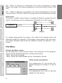
Hysteresis
To ensure a stable output (when a measured distance equals the set-
point), a hysteresis can be programmed. Example for a NO output:
If a target approaches the sensor, the output will change when the
distance equals the setpoint. If the target moves back from this point,
the output changes back when the distance equals the setpoint + hys-
teresis.
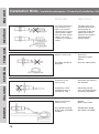
File Menu
Collect and Save values
By choosing this, a new window opens. The frequency of the measure-
ments can be selected (seconds, minutes and hours).
“Start” starts the recording.
“Save” stores the values (these can be evaluated in Excel).
Write sensor parametres
The parametres of the actual dis-
played settings are written in a file on
disc.
Load sensor parametres
The parameters from a file on disc are
loaded into the sensor.
Sensor
Target
Output
Setpoint Setpoint
+ hysteresis

7
ENGLISH
ENGLISH
FRANÇAIS
ESPAÑOL
ITALIANO
DANSK DEUTSCH
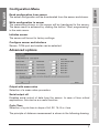
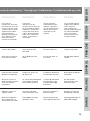
Configuration Menu
Read configuration from sensor
The actual configuration will be downloaded from the sensor and shown.
Write configuration to sensor
The parametres shown on the screen will be transferred to the sensor.
The same result is achieved by clicking the button “Start programming”
in the main menu.
Initialize sensor
The sensor will be set to factory settings.
Configure sensor and interface
Sensor, COM-port and similar can be selected.
Advanced options
Output with mean value
Selection of a mean value procedure.
Serial output off
Disables serial output of data from the sensor. In case of time critical
applications, this can be a a useful function.
Cycle Time
Selection of cycle time in steps of 64, 32, 16, 8 or 4 ms.
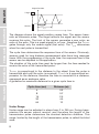
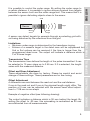
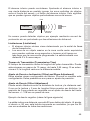
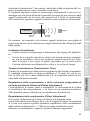
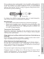
The principle of distance measurement is shown in the following drawing.

8
ENGLISHDEUTSCHFRANÇAISESPAÑOLITALIANODANSK
The diagram shows the signal position versus time. The sensor trans-
mits an ultrasonic pulse. The target reflects the signal and the sensor
receives this echo. The front of the sensor generates a new echo, an
echo of the echo. This is a weak signal for no use - therefore the T
measure
gates through only the usable signal (first echo). The T
cycle
determines
when the next pulse is transmitted.
The cycle time determines the response time of the sensor. Obviously,
sensors used for long distance measurement also have long response
times. With the programming of the cycle time, the response time of the
sensor can be adjusted to the application.
The duration of the cycle time must be longer than the time needed to
receive the echo of the transmitted pulse!
T
measure
is proportional to the distance to the object (from the pulse is
transmitted and until the echo is received). T
measure
is a proportional ex-
pression for the distance; therefore the time is converted to a distance,
expressed as an analogue value.
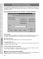
A guideline for maximum distance for a given cycle time is:
Under Range
Under range can be adjusted in steps from 0 to 255 cm. During trans-
mission the sensor cannot receive, and therefore the length of the
transmission pulse determines the shortest detection distance. This
range, limited by the length of the transmission pulse, is called the blind
zone.
Target
Sensor
Signal Position
Time
T
measure
T
cycle
Cycle time (ms) Distance (m)
4 0.3
8 0.7
16 2.5
32 4.5
64 10

9
ENGLISH
FRANÇAIS
ESPAÑOL
ITALIANO
DANSK DEUTSCH
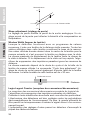
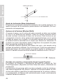
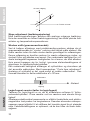
It is possible to control the under range. By setting the under range to
a certain distance, it is possible to ignore echoes received from targets
between the sensor front and the under range limit. This means that it is
possible to ignore disturbing objects close to the sensor.
A sensor can detect targets for example through a protecting grid with-
out being disturbed by the reflections from this grid.
Limitations
• Minimum under range is determined by the transducer ringing.
• Echoes of a massive target in the dead zone will be suppressed but
2nd or 3rd echoes can be received if the time is longer than the
programmed dead zone. The output will indicate a distance which is
2 or 3 times longer.
Transmission Time
The transmission time defines the length of the pulse transmitted. It can
be selected in 10 µsec steps up to 2.55 ms. If 0 is selected, the length
varies with the measured distance.
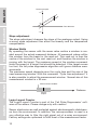
Offset and Slope Adjustment
These adjustments are done by factory. Please be careful and avoid
change of these settings. These parameters are for fine-tuning.
Offset Adjustment
A difference can exist between the read-out and the real distance.
0 mm in the read-out and 0 mm in the physical length might differ. The
position of 0 mm can be adjusted with the sensor head offset adjust-
ment +/-128 mm in mm steps.
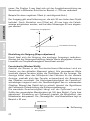
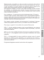
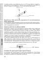
Example of negative offset (see following drawing):
The output indicates a distance which is 30 mm behind the target. By
setting the offset to -30 mm, this misreading is neutralized as 30 mm
are subtracted from all measurements.
Target
Sensor
Grid
Blind
zone
Under
range

10
ENGLISHDEUTSCHFRANÇAISESPAÑOLITALIANODANSK
Slope adjustment
The slope adjustment changes the slope of the analogue output. Using
a wrong slope adjustment can affect the linearity and the temperature
compensation.
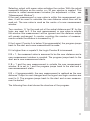
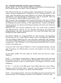
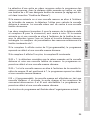
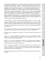
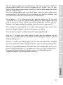
Window Width
By operating the sensor with the mean value routine a window is cre-
ated around the actual measured distance. All measured values within
this window form the basis for the read-out. This read-out is then the
centre of the window for the next read-out, and therefore the window is
moving with the target. The maximum speed of the window movement
limits the speed of a target that should be detected. If the target moves
too fast, the fail pulse suppression algorithm will ignore distance mea-
surements.
The maximum speed depends upon the cycle time and the size of the
used measuring window. With the command “Cycle time adjustment” it
is also possible to adjust the measurement window. Normal size of this
measurement window is ± 32 mm.
Login-Logout Counter
The Login-Logout Counter is part of the ‘Fail Pulse Suppression’ soft-
ware of the sensor. Please change only with caution!
Sensor electronics are well protected against electromagnetic disturbanc-
es from the environment. In addition, the microprocessor is used in a
very effective way to filter the right signal out of a noisy environment.
Factory settings are optimised to fulfill most of the measurement tasks.
127
30
-128
Real distance
Distance output
Measurement window
Actual
output
Distance

11
ENGLISH
FRANÇAIS
ESPAÑOL
ITALIANO
DANSK DEUTSCH
Selecting output with mean value activates the routine. With the actual
measured distance as the centre, a ± 32 mm window is created. This
window is called measurement window (for adjustment of this, see
“Measurement Window”).
If the next measurement or new value is within this measurement win-
dow, it will be used to calculate the new distance which then will be
read-out. The new value is used as the centre of a new measurement
window.
Two counters, ‘A’ for the read-out of the actual distance and ‘B’ for the
login, are reset to 0. If the next measurement or new value is outside
the window this measurement will be ignored and the distance output
will remain unchanged. A counter counting the number of measure-
ments outside the window is increased by 1.
If the Logout Counter A is below 3 (programmable), the program jumps
back to the start and a new measurement is made.
If it is higher than or equals 3, the Login Counter B is increased.
If B = 1, the measured value is assumed to be the new distance and a
new measurement window is created. The program jumps back to the
start and a new measurement starts.
If B > 1 and the new measurement is outside the new measurement
window, B is set to 1 and the program jumps back to the start and a
new measurement starts.
If B = 4 (programmable), the new measurement is realised as the new
distance. Output is now changed and the logout and login counters are
reset to 0. The program jumps back to the start and a new measure-
ment is started.
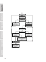
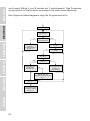
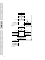
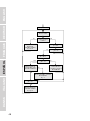
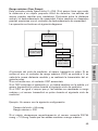
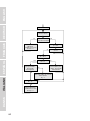
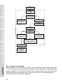
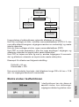
The following flow chart shows the structure of the program.

12
ENGLISHDEUTSCHFRANÇAISESPAÑOLITALIANODANSK
A & B = 0
Start
New value
Within range of
old measurement?
Yes
No
A = A+1
A ≥ 3?
No
Yes
Calculate new
distance
Change outputs
A & B = 0
B = B+1
B = 1?
No
Yes
B = 4?
No
Yes
Yes
No
New value =
New distance
Change outputs
A & B = 0
New value in
“possible”
measurement
window
New value is centre of
“possible”
measurement window
B = 1
New value is cen-
tre of “possible”
measurement
window

13
ENGLISH
FRANÇAIS
ESPAÑOL
ITALIANO
DANSK DEUTSCH
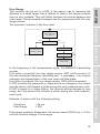
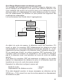
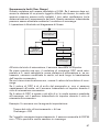
Over Range
This counter can be set to 0-255. If the sensor has to measure the
distance to a small target that is difficult to detect, the sensor outputs
may be very unstable. They will flicker between the actual distance and
over range. These unwanted changes can be suppressed with the over
range counter.
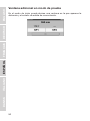
The operation is shown in the flow chart:
In the beginning of the measurement cycle, the sensor is transmitting
a pulse.
If an echo is received, the over range counter ORC will be reset to 0,
the new measured distance calculated and - if necessary - the outputs
changed, and transmission of the next pulse will take place.
If no echo is received, the over range counter ORC will be increased.
If ORC is below the parameter p, there will be no changes in the output
and the sensor will transmit a pulse during the next measurement cycle.
If ORC is equal to or higher than p, the outputs will be changed to over
range, and the sensor will transmit a pulse during the next measure-
ment cycle.
Example: A sensor with the following setting:
Cycle time = 64 ms
Over Range = 200
If the target suddenly disappears, the sensor needs 200*64 ms = 12.8 s
until the outputs change to over range.
Yes
No
Echo received?
No
Yes
Start new cycle
Send pulse
Increase ORC
ORC ≥ p?
Change output to
Over range
Set ORC = 0
Calculate distance
Change outputs

14
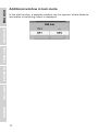
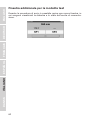
Additional window in test-mode
In the start modus, a separate window can be opened, where distance
and status of switching output is displayed.
ENGLISHDEUTSCHFRANÇAISESPAÑOLITALIANODANSK

15
ENGLISH
FRANÇAIS
ESPAÑOL
ITALIANO
DANSK DEUTSCH
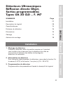
Ultraschall, Abstandssensor
programmierbare Ausgänge
Typen UA 30 CLD .. F. M7
INHALT Seite
Installation 15
Beschreibung der Software 16
Technische Daten 74
Erfassungsbereich 76
Abmessungen 76
Schaltung 77
Hinweise zur Installation 78
1. Montage des Sensors
Montieren Sie den Sensor in der gewünschten Position mit
Ausrichtung auf das Objekt. Kontrollieren Sie, dass der
Objektabstand innerhalb der Sensorreichweite liegt.
2. Sensorversorgung
Zur Sensorversorgung ist Pin 2 an Erde (0 V DC) und Pin 1 an +
(19 -30 V DC) zu verbinden.
3. Programmierung des Sensors
Die Parameter werden entsprechend der Software-Beschreibung
eingegeben.
Installation

16
ENGLISHDEUTSCHFRANÇAISESPAÑOLITALIANODANSK
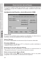
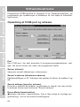
Beschreibung der Software
Das für die Windows-Plattform konzipierte Programm UDSProg.EXE er-
leichtert die Konfiguration des Sensors anhand selbsterklärender Menüs.
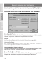
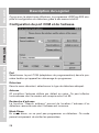
Konfiguration von COM Schnittstelle und Adresse
Schnittstelle (Port)
Die COM Schnittstelle für den Programmieradapter wird im ersten
Fenster ausgewählt, das beim Programmstart erscheint.
Sensor
Im Drop-down-Menü wird der korrekte Sensortyp ausgewählt.
Adresse (Address)
Die werkseitige Einstellung ist 97, doch lässt sich diese Adresse in
einen beliebigen Wert zwischen 0 und 99 ändern.
Adresse suchen (Search address)
Wird ein Sensor mit einer unbekannten Adresse angeschlossen, findet
man mit der Funktion „Adresse suchen“ die korrekte Adresse.
Demo-Modus (Demo-Mode)
Der Sensor läuft auch im Demo-Modus. Eine Programmierung ist nicht
möglich, es lassen sich lediglich die Einstellungen überprüfen.

17
ENGLISH
FRANÇAIS
ESPAÑOL
ITALIANO
DANSK DEUTSCH
Initialisieren des Sensors (Initialize sensor)
Der Sensor wird auf die werkseitigen Einstellungen zurückgestellt.
OK
Die Einstellungen wurden bestätigt und das Hauptmenü erscheint.
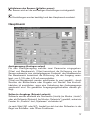
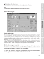
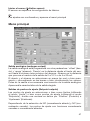
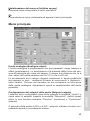
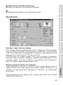
Hauptmenü
Analogausgang (Analogue output)
Für den Analogausgang werden zwei Parameter eingegeben:
Offset und Messbereich. Offset bezeichnet die Entfernung von der
Sensorvorderseite zum nächstgelegenen Endpunkt des Messbereichs.
Der Messbereich bezeichnet die Entfernung, die den Ausgang veran-
lasst, von 0-10V oder 4-20 mA umzuschalten.
Offset und Messbereich werden schrittweise (in mm) gewählt – durch
Scrollen der Bildlaufleiste oder Eingabe von Werten. Das Kontroll-
kästchen ist anzuklicken, wenn eine Umkehrung des Analogausgangs
gewünscht wird. Die gewählten Ausgangseigenschaften werden ge-
zeigt.
Sollwerte-Ausgänge (Setpoint outputs)
Sollwerte werden entweder als Grenzwerte (Limits) (im Modus „Limits“)
oder als Sollwerte (Setpoint) (im Modus „Setpoints“) gewählt, wobei ein
Fenster für „Position“ und „Hysterese“ vorhanden ist.
Je nach Wahl (NO oder NC), handelt es sich bei den Sollwerten in der
Regel um Schließer- oder Öffner-Funktionen.

18
ENGLISHDEUTSCHFRANÇAISESPAÑOLITALIANODANSK
NO: Wird ein Sollwert überschritten, ist die Ausgangsimpedanz hoch.
Innerhalb des Messbereichs ist die Ausgangsimpedanz niedrig und es
fließt Strom (<100 mA).
NC: Wird ein Sollwert überschritten, ist die Ausgangsimpedanz nied-
rig und es fließt Strom (< 100 mA). Innerhalb des Messbereichs ist die
Ausgangsimpedanz hoch.
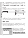
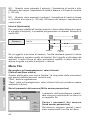
Hysterese (Hysteresis)
Um einen stabilen Ausgang zu gewährleisten (wenn eine gemessene
Entfernung dem Sollwert entspricht), kann eine Hysterese festgelegt
werden. Beispiel für einen NO-Ausgang:
Wenn sich ein Objekt dem Sensor nähert, ändert sich der Ausgang,
wenn die Entfernung dem Sollwert entspricht. Entfernt sich das Objekt
von diesem Punkt, geht der Ausgang zurück, wenn die Entfernung dem
Sollwert zuzüglich der Hysterese entspricht.
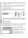
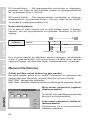
Datei-Menü
Erfassen und Speichern von Werten
Bei dieser Auswahl öffnet sich ein neues Fenster. Die Frequenz der
Messungen kann gewählt werden (Sekunden, Minuten und Stunden).
„Start“ startet die Erfassung.
„Speichern“ speichert die Werte ab (die sich mithilfe des Programms
Excel auswerten lassen).
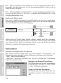
Ablegen von Sensor-Parametern
Die Parameter der aktuell angezeigten
Einstellungen werden in einer Datei
auf der Festplatte abgelegt.
Laden der Sensor-Parameter
Die Parameter aus einer Datei auf der
Festplatte werden in den Sensor gela-
den.
Sensor
Objekt
Ausgang
Sollwert Sollwert
+ Hysterese

19
ENGLISH
FRANÇAIS
ESPAÑOL
ITALIANO
DANSK DEUTSCH
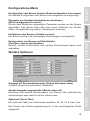
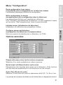
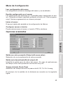
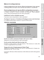
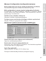
Konfigurations-Menü
Konfiguration vom Sensor einlesen (Read configuration from sensor)
Die aktuelle Konfiguration des Sensors wird abgerufen und angezeigt.
Übergabe von Konfigurationsdaten an den Sensor
(Write configuration to sensor)
Die auf dem Bildschirm angezeigten Parameter werden an den Sensor
übermittelt. Das gleiche lässt sich auch durch Anklicken der Schalt-
fläche „Programmierung starten“ (Hauptmenü) erreichen.
Initialisieren des Sensors (Initialize sensor)
Der Sensor wird auf die werkseitigen Einstellungen zurückgestellt.
Konfiguration von Sensor und Schnittstelle
(Configure sensor and interface)
Sensor, serielle Schnittstelle und weitere Einstellungen lassen sich
auswählen.
Weitere Optionen
Ausgang mit Durchschnittswerten (Output with mean value)
Auswahl eines Durchschnittwert-Verfahrens.
Serielle Ausgabe ausgeschaltet (Serial output off)
Deaktiviert die serielle Datenausgabe vom Sensor. Bei zeitkritischen
Anwendungen kann diese Funktion hilfreich sein.
Zykluszeit (Cycle Time)
Die Zykluszeit lässt sich stufenweise einstellen: 64, 32, 16, 8 oder 4 ms.
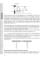
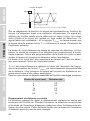
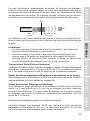
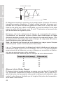
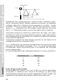
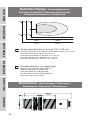
Das Prinzip der Entfernungsmessung ist in der nachfolgenden Grafik
dargestellt.

20
ENGLISHDEUTSCHFRANÇAISESPAÑOLITALIANODANSK
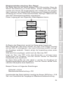
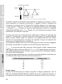
Das Schaubild zeigt die Signalposition im Verhältnis zur Zeit. Der
Sensor sendet einen Ultraschallimpuls aus. Das Objekt reflektiert
das Signal, und dieses Echo wird vom Sensor empfangen. An der
Vorderseite des Sensors wird ein neues Echo erzeugt, also ein Echo
des Echos. Da es sich hierbei um ein schwaches nicht verwendbares
Signal handelt – lässt T
measure
(Messzeit) nur das nutzbare Signal durch
(erstes Echo). Mit T
cycle
(Zykluszeit) wird festgelegt, wann der nächste
Impuls übermittelt wird.
Mit der Zykluszeit wird die Reaktionszeit des Sensors festgelegt. Natür-
lich weisen Sensoren mit größerer Reichweite auch längere Reaktions-
zeiten auf. Bei der Eingabe der Zykluszeit lässt sich auch die Reaktions-
zeit des Sensors nach Einsatzbereich einstellen.
Die Zykluszeit muss länger andauern als die Zeit, die zum Empfangen
des Echos nach der Aussendung des Impulses erforderlich ist!
T
measure
ist proportional der Entfernung zum Objekt (von der Aussendung
des Impulses bis zum Empfangen des Echos). T
measure
ist ein propor-
tionaler Ausdruck für die Entfernung, weshalb die Zeit in Entfernung
umgerechnet und als analoger Wert angegeben wird.
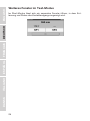
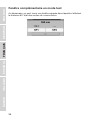
Eine Richtlinie für die maximale Reichweite innerhalb einer bestimmten
Zykluszeit ist:
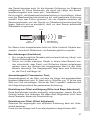
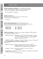
Messbereichsunterschreitung (Under Range)
Diese lässt sich stufenweise von 0 bis 255 cm einstellen. Während der
Aussendung ist der Sensor nicht empfangsbereit, weshalb die Länge
Objekt
Sensor
Signalposition
Zeit
T
measure
T
cycle
Zykluszeit (ms) Entfernung (m)
4 0.3
8 0.7
16 2.5
32 4.5
64 10
Seite laden ...
Seite laden ...
Seite laden ...
Seite laden ...
Seite laden ...
Seite laden ...
Seite laden ...
Seite laden ...
Seite laden ...
Seite laden ...
Seite laden ...
Seite laden ...
Seite laden ...
Seite laden ...
Seite laden ...
Seite laden ...
Seite laden ...
Seite laden ...
Seite laden ...
Seite laden ...
Seite laden ...
Seite laden ...
Seite laden ...
Seite laden ...
Seite laden ...
Seite laden ...
Seite laden ...
Seite laden ...
Seite laden ...
Seite laden ...
Seite laden ...
Seite laden ...
Seite laden ...
Seite laden ...
Seite laden ...
Seite laden ...
Seite laden ...
Seite laden ...
Seite laden ...
Seite laden ...
Seite laden ...
Seite laden ...
Seite laden ...
Seite laden ...
Seite laden ...
Seite laden ...
Seite laden ...
Seite laden ...
Seite laden ...
Seite laden ...
Seite laden ...
Seite laden ...
Seite laden ...
Seite laden ...
Seite laden ...
Seite laden ...
Seite laden ...
Seite laden ...
Seite laden ...
Seite laden ...
-
 1
1
-
 2
2
-
 3
3
-
 4
4
-
 5
5
-
 6
6
-
 7
7
-
 8
8
-
 9
9
-
 10
10
-
 11
11
-
 12
12
-
 13
13
-
 14
14
-
 15
15
-
 16
16
-
 17
17
-
 18
18
-
 19
19
-
 20
20
-
 21
21
-
 22
22
-
 23
23
-
 24
24
-
 25
25
-
 26
26
-
 27
27
-
 28
28
-
 29
29
-
 30
30
-
 31
31
-
 32
32
-
 33
33
-
 34
34
-
 35
35
-
 36
36
-
 37
37
-
 38
38
-
 39
39
-
 40
40
-
 41
41
-
 42
42
-
 43
43
-
 44
44
-
 45
45
-
 46
46
-
 47
47
-
 48
48
-
 49
49
-
 50
50
-
 51
51
-
 52
52
-
 53
53
-
 54
54
-
 55
55
-
 56
56
-
 57
57
-
 58
58
-
 59
59
-
 60
60
-
 61
61
-
 62
62
-
 63
63
-
 64
64
-
 65
65
-
 66
66
-
 67
67
-
 68
68
-
 69
69
-
 70
70
-
 71
71
-
 72
72
-
 73
73
-
 74
74
-
 75
75
-
 76
76
-
 77
77
-
 78
78
-
 79
79
-
 80
80


CARLO GAVAZZI UA 30 CLD Benutzerhandbuch
- Kategorie
- Komfortbeleuchtung
- Typ
- Benutzerhandbuch
- Dieses Handbuch ist auch geeignet für
in anderen Sprachen
- English: CARLO GAVAZZI UA 30 CLD User manual
- français: CARLO GAVAZZI UA 30 CLD Manuel utilisateur
- español: CARLO GAVAZZI UA 30 CLD Manual de usuario
- italiano: CARLO GAVAZZI UA 30 CLD Manuale utente
- dansk: CARLO GAVAZZI UA 30 CLD Brugermanual
