
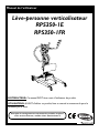
User Manual
DEALER: This manual MUST be given to the user of the product.
USER:
BEFORE using this product, read this manual and save for future reference.
For more information regarding
Invacare products, parts, and services,
please visit www.invacare.co.uk
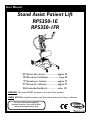
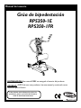
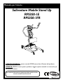
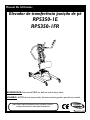
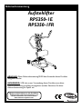
Stand Assist Patient Lift
RPS350-1E
RPS350-1FR
ES Manual del usuario ......................página 25
FR Manuel de l'utilisateur................... page 49
IT Manuale per l'utente....................pagina 73
PT Manual do utilizador...................página 97
DE Anwenderhandbuch....................seite 121

SYMBOL LEGEND
Stand Assist Patient Lift 2 Part No. 1078985
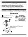
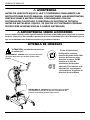
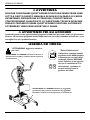
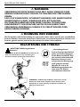
WARNING
DO NOT OPERATE THIS EQUIPMENT WITHOUT FIRST READING AND
UNDERSTANDING THIS MANUAL. IF YOU ARE UNABLE TO UNDERSTAND
THE WARNINGS, CAUTIONS AND INSTRUCTIONS CONTACT A
QUALIFIED DEALER OR INVACARE TECHNICAL SUPPORT BEFORE
ATTEMPTING TO USE THIS EQUIPMENT - OTHERWISE INJURY OR
DAMAGE MAY RESULT.
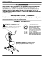
ACCESSORIES WARNING
Invacare products are specifically designed and manufactured for use in conjunction with Invac-
are accessories. Accessories designed by other manufacturers have not been tested by Invacare
and are not recommended for use with Invacare products.
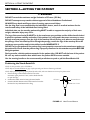
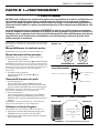
SYMBOL LEGEND
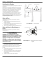
"ATTENTION, see instructions for use".
WARNING - ALWAYS be aware of the Lift Arm.
Injury to the patient and/or assistant may occur.
2010
"Date of Manufacture"
Device contains Lead Acid
batteries. DO NOT dispose of
batteries in normal household
waste. They MUST be taken
to a proper disposal site.
Contact your local waste
management company for
information.
WARNING - ALWAYS be aware of the Footrest, especially
the patient’s position on the footrest. Injury to the patient
and/or assistant may occur.

TABLE OF CONTENTS
Part No. 1078985 3 Stand Assist Patient Lift
TABLE OF CONTENTS
SYMBOL LEGEND .............................................................................................. 2
SPECIAL NOTES ................................................................................................ 5
PRODUCT PARAMETERS .................................................................................. 6
RPS350-1E and RPS350-1FR Stand Assist Patient Lift ...................................................................................................6
SECTION 1—GENERAL GUIDELINES ................................................................... 7
Weight Limitation ..................................................................................................................................................................7
Assembling the Lift.................................................................................................................................................................7
Using the Sling.........................................................................................................................................................................7
Operating the Lift...................................................................................................................................................................8
Lifting the Patient ...................................................................................................................................................................8
Transferring the Patient........................................................................................................................................................8
Performing Maintenance.......................................................................................................................................................8
SECTION 2—ASSEMBLY ..................................................................................... 9
Unpacking the Patient Lift ....................................................................................................................................................9
Assembling the Patient Lift...................................................................................................................................................9
Assembling the Mast Assembly to the Base................................................................................................................9
Preparing Lift for Use............................................................................................................................................................9
Install the Shifter Handle ......................................................................................................................................................9
Attaching the Battery Charger Mounting Bracket to the Wall................................................................................ 10
SECTION 3— OPERATION ............................................................................... 11
Locking/Unlocking the Rear Casters .............................................................................................................................. 11
Raising/Lowering the Patient Lift ..................................................................................................................................... 11
Closing/Opening the Legs.................................................................................................................................................. 11
Using the Emergency Stop ................................................................................................................................................ 11
Activating a Mechanical Emergency Release................................................................................................................. 12
Primary Emergency Release......................................................................................................................................... 12
Secondary Emergency Release .................................................................................................................................... 12
Charging the Battery .......................................................................................................................................................... 12
Using a Power Cord to Charge the Battery ............................................................................................................ 12
Using the Battery Charger to Charge the Battery ................................................................................................. 13
SECTION 4—LIFTING THE PATIENT ................................................................. 14
Positioning the Stand Assist Lift....................................................................................................................................... 14
Lifting the Patient ................................................................................................................................................................ 15
Moving the Patient .............................................................................................................................................................. 16
SECTION 5—TRANSFERRING THE PATIENT ..................................................... 17
Transferring to a Commode Chair................................................................................................................................. 18
Transferring to a Wheelchair........................................................................................................................................... 19
Transferring to a Bed ......................................................................................................................................................... 19

TABLE OF CONTENTS
Stand Assist Patient Lift 4 Part No. 1078985
TABLE OF CONTENTS
SECTION 6—TROUBLESHOOTING .................................................................... 20
SECTION 7—MAINTENANCE ........................................................................... 21
Maintenance Safety Inspection Checklist....................................................................................................................... 21
Cleaning the Sling and the Lift.......................................................................................................................................... 21
Detecting Wear and Damage........................................................................................................................................... 21
Lubricating the Lift .............................................................................................................................................................. 22
Adjusting the Base............................................................................................................................................................... 22
Adjusting the Knee Pad Height........................................................................................................................................ 22
Replacing the Electric Actuator ....................................................................................................................................... 23
CUSTOMER SALES, SERVICE AND WARRANTY INFORMATION ......................... 24

SPECIAL NOTES
Part No. 1078985 5 Stand Assist Patient Lift
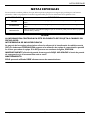
SPECIAL NOTES
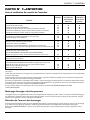
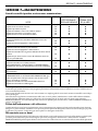
Signalwordsareusedinthismanualandapplytohazardsorunsafepracticeswhichcouldresultinpersonalinjuryor
propertydamage.Refertothetablebelowfordefinitionsofthesignalwords.
NOTICE
THE INFORMATION CONTAINED IN THIS DOCUMENT IS SUBJECT TO CHANGE
WITHOUT NOTICE.
RADIO FREQUENCY INTERFERENCE
Most electronic equipment is influenced by Radio Frequency Interference (RFI). CAUTION
should be exercised with regard to the use of portable communication equipment in the area
around such equipment. If RFI causes erratic behavior, PUSH the RED Emergency Stop Button
IMMEDIATELY. DO NOT turn the Red Emergency Stop Button OFF while transmission is in
progress.
MAINTENANCE
Maintenance MUST be performed ONLY by qualified personnel.
SIGNAL WORD MEANING
DANGER
Danger indicates an imminently hazardous situation which, if not avoided, will result in death or seri-
ous injury.
WARNING
Warning indicates a potentially hazardous situation which, if not avoided, could result in death or
serious injury.
CAUTION
Caution indicates a potentially hazardous situation which, if not avoided, may result in property dam-
age or minor injury or both.

PRODUCT PARAMETERS
Stand Assist Patient Lift 6 Part No. 1078985
PRODUCT PARAMETERS
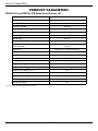
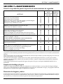
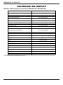
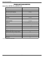
RPS350-1E and RPS350-1FR Stand Assist Patient Lift
*NOTE:Variesdependinguponloadandstroke.
Height at Sling Hook-up - MAX.: 66 inches
Height at Sling Hook-up - MIN.: 40 inches
Base Width OPEN: 37 inches
Base Width CLOSED: 26 inches
Base Height (Clearance): 4.5 inches
Base Length: 35.5 inches
Overall Height: 49 inches
Overall Length: 39 inches
Overall Width: 25.8 inches
Caster Size (FRONT)
Caster Size (REAR)
3.0 inches
5.0 inches
Sling Options: Stand Assist or Transfer Stand Assist
Sling Material: Polyester
Weight Capacity: 350 lbs
Weight Out of Carton: 108 lbs
Battery: 24V DC (RCHBL)
Charger Input: 100-240V AC
Charger Output/Charging Time: 29.5V DC Max 6 hours
Audio/Visual Low Battery Alarm: Yes
Motor Safety Devices: Anti-Entrapment
*Approx. Lifts per Charge: *100-200 Cycles per charge
Limited Warranty Lift/Electronics: 3 Years/2 Years
Emergency Stop Button: Yes

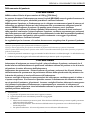
SECTION 1—GENERAL GUIDELINES
Part No. 1078985 7 Stand Assist Patient Lift
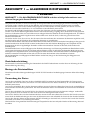
SECTION 1—GENERAL GUIDELINES
WARNING
SECTION 1 - GENERAL GUIDELINES contains important information for the safe operation
and use of this product.
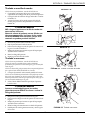
Checkallpartsforshippingdamagebeforeusing.Incaseofdamage,DONOTusetheequipment.ContacttheDealerfor
furtherinstructions.
TheInvacarepatientliftisNOTatransportdevice.Itisintendedtotransferanindividualfromoneseatedsurfacetoanother
(suchasabedtoa
wheelchair).
DONOTattemptanytransferwithoutapprovalofthepatient’sphysician,nurseormedicalassistant.Thoroughlyreadthe
instructionsinthisOwner’sManual,observeatrainedteamofexpertsperformtheliftingproceduresandthenperformthe
entireliftprocedureseveraltimeswithpropersupervisionandacapableindividualacting
asapatient.
Usetheslingthatisrecommendedbytheindividual’sdoctor,nurseormedicalassistantforthecomfortandsafetyofthe
individualthatisbeinglifted.
Ifthe patientliftisusedintheareaofashowerorbath,ensurethatthepatientliftiswipedcleanof
anymoistureafteruse. DO
NOTstoretheliftinadampareaorinadampcondition.Periodicallyinspectallc omponents ofthepatientliftforsignsof
corrosion.Replaceallpartsthat arecorr odedordamaged.
TheStandAssistliftmaybeoperatedbyonehealthcareprofessionalforall
liftingpreparation,transferringfromandtransferring
toprocedureswithacooperative,partialweight‐bearingpatient.How ev er,sincemedicalconditionsvary ,Inv acare recommends
thatthehealthcareprofessionalevaluatetheneedforassistanceanddeterminewhethermorethanoneassistantisappropriatein
eachcasetosaf elyperformthetransfer .
Theuse
ofthepatientliftbyoneassistantshouldbebasedontheevaluation ofthehealthcareprofessionalforeachindividualcase.
Weight Limitation
DONOTexceedmaximumweightlimitationofthepatientlift.Theweightlimitationforthepatientliftis25stone(350lbs).
Assembling the Lift
DONOTovertightenmountinghardware.Thiswilldamagemountingbrackets.
Using the Sling
StandAssistSlings:DONOTusethestandassistslingincombinationwiththepatientliftasatransportdevice.Itis
intendedtotransferanindividualfromonerestingsurfacetoanother(suchasabedtoawheelchair).
StandAssistSlings:Beforeliftingthepatient,makesurethebottom
edgeofthestandassistslingispositionedonthelower
backofthepatientandthepatient’sarmsareoutsidethestandassistsling.
StandAssistSlings:ThebeltMUSTbesnug,butcomfortableonthepatient,otherwisethepatientcanslideoutofthesling
duringtransfer,possiblycausing
injury.
TransferSlings:Beforeliftingthepatient,makesurethebottomedgeofthetransferslingisatthebaseofthespineandthe
patient’sarmsareoutsidethetransfersling.
TransferSlings:DONOTraisethepatienttoafullstandingpositionwhileusingthetransfersling,otherwiseinjurymay
occur.
Aftereac hlaun deri ng(inaccordancewithinstructionsonthesling),inspectsling(s)forwear,tears,andloosestitching.
Bleached,torn,cut,frayed,orbrokenslingsareunsafeandcould resultininjury.Discardimmed iately.
DONOTalterslings.
Besuretochecktheslingattachmentseachtimetheslingisremoved
andreplaced,toensurethatitisproperlyattachedbefore
thepatientisremovedfromastationaryobject(bed,chairorcommode).
Ifthe patientisin awheelchair,securethewheel locksinplacetopreventthechairfrommovingforw ardsorbac kw ards.

SECTION 1—GENERAL GUIDELINES
Stand Assist Patient Lift 8 Part No. 1078985
Operating the Lift
Makesurethereisanaudibleclickwhenmountingbatteryonthebatterychargertoconfirmpropermounting.Otherwise,
injuryordamagemayoccur.
Usethehandlestopushorpullthepatientlift.
Lifting the Patient
BeforepositioningthelegsoftheStandAssistliftaroundthepatient,makesurethatthepatient’sfeetareoutofthewayofthefoot
plate,otherwiseinjurymayoccur .
Adjustmentsforsafetyandcomfortshouldbemadebeforemov ingthepatient.Patientʹsarms shouldbeoutsideofthe
sling
straps.
Beforeliftingapatientfromastationaryobjec t(wheelchair ,commodeorbed),slightlyraisethepatientoffthestationaryobject
andchec kthatallslingattachmentsaresecure.Ifany a ttachmentisnotcorr ect,low erthepatientandcorrecttheproblem,then
raisethepatientandcheckagain.
Duringtransfer,
withthepatientsuspendedinaslingattachedtothelift,DONOTrollcasterbaseov e runev ensurfacesthat
wouldcreateanimbalanceofthepatientliftandcouldcausethepatientlifttotipov e r.UsesteeringhandleonthemastatALL
timestopushorpull
thepatientlift.
Inv acarerecommend slockingtherearswivelcastersONLYwhenpositioningorremovingthesling(standassistortransfer)from
aroundthepatient.
Inv acaredoesNO T recommendlockingoftherearcastersof thepatient liftwhenliftinganindividual.Doin gsoco uldcausethe
lifttotipandendanger
thepatientandassistants.InvacareDOESrecommendthattherearcaster sbeleftunlockedduringlifting
procedurestoallowthepatientlifttostabilizeitselfwhe nthepatientisinitiallyliftedfromachair,bed oranystationaryobject.
Transferring the Patient
Beforetransferring,checkthattheproduct’sweightcapacitycanwithstandthepatientʹsweight.
WheelchairwheellocksMUSTbeinalock edpositionbeforelow eringthepatientintothewheelchairfortransport.
Performing Maintenance
Regularmainte nanceofpatientliftsandaccessoriesisnece ssarytoassureproperoperation.
Afterthe first12monthsofoperation,inspectallpivotpointsandfastenersforwear .Ifthemetalisworn,thepartsMUSTbe
replaced.Performthisinspectioneverysixmonthsthereafter.
DONOTov ertightenmountinghardware.Thiswill
da magemountingbrackets.
Castersand axleboltsrequireinspectionseverysixmo nthstoch eckfortightnessandwear .

SECTION 2—ASSEMBLY
Part No. 1078985 9 Stand Assist Patient Lift
SECTION 2—ASSEMBLY
Unpacking the Patient Lift
Unpackthecomponentsfromtheshippingcarton.
Assembling the Patient Lift
WARNING
Use only Invacare parts in the assembly of this
patient lift. The base legs, the mast, boom, pump
assembly and swivel bar are manufactured to
specifications that assure correct alignment of all
parts for safe functional operation.
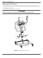
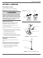
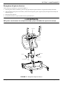
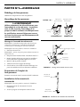
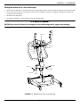
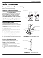
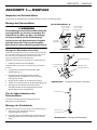
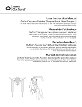
Assembling the Mast Assembly to the Base
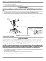
NOTE:Themastassemblymayberemovedfr omthebaseforstorage
ortransporting.ThemastassemblyMUSTbeproperlysecuredtothe
baseassemblybefor euse.
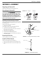
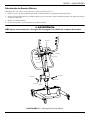
NOTE:Forthisprocedure,refertoFIGURE 2.1.
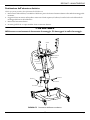
1. Putthebaseonthefloor.
NOTE:Make sureallfourcastersmakecontactwiththefloor.
2. Lockboth
re arcasters.RefertoDetail“A” .
3. Removethehexbolt,washersandnutthatarelocatedin
theU‐shapecut‐outofthebase.
4. Liftthemasttoanuprightposition.
5. Lowerthemastontothemoun tingbracket.
6. Attachthemasttothebasewiththehexbolt,washersand
nut.
Tightensecur ely.
Preparing Lift for Use
CheckandtightenallhardwareBEFOREuse.
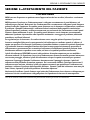
Install the Shifter Handle
NOTE:Forthisprocedure,refertoFIGURE 2.2.
1. Removetheshifterhandlefromthepackagingcarton.
2. Threadtheshifterhandleontothemaleadapteronthe
base.
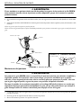
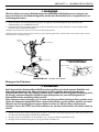
FIGURE 2.1 Assembling the Mast Assembly to the Base
FIGURE 2.2 Install the Shifter Handle
Step Here
to Lock
Step Here
to Unlock
Nut
Washer
Hex Bolt
Mounting Bracket
Locking
Lever
LOCKED
UNLOCKED
DETAIL “A”
Washer
Shifter Handle
Male Adapter
in Base

SECTION 2—ASSEMBLY
Stand Assist Patient Lift 10 Part No. 1078985
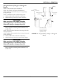
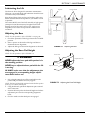
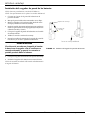
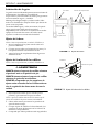
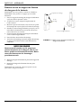
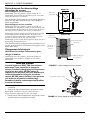
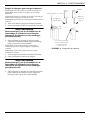
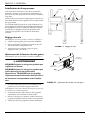
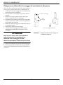
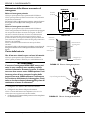
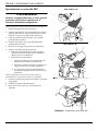
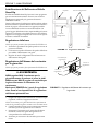
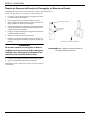
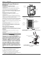
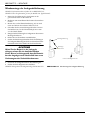
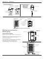
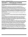
Attaching the Battery Charger Mounting Bracket to the Wall
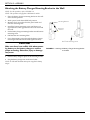
NOTE:Forthisprocedure,refertoFIGURE 2.3.
NOTE:ThisprocedureonlyappliestoRPS350‐1Emodels.
1. Placethebatterychargermountingbracketonthewall
atthedesiredposition.
2. Withapencil,markthemiddleholeposition.
3. Measuredown6½inchesfromthepencilmarkand
drillonemountinghole.
4. Installthebottom
mountingscrewuntilthereisan
approximate1/8‐inchgapbetweenthescrewheadand
thewall.
5. Putthebatterychargermountingbracketontothebottom
mountingscrew.
6. Drilltheothertwomountingholes.
7. Screwthemountingscrewsthroughthebatterycharger
mountingbracketandintothew all.Tightensecurely.
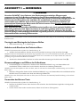
CAUTION
Make sure there is an audible click when mount-
ing battery on the battery charger to confirm
proper mounting. Otherwise, injury or damage
may occur.
8. Putthebatterychargerinplaceonthemountingbracket.
9. Plugthebatterychargerintoanelectricaloutlet.
NOTE:AnLEDwillilluminatewhenpoweris appliedtobattery
charger.
FIGURE 2.3 Attaching the Battery Charger Mounting Bracket
to the Wall
Mounting Bracket
Mounting
Screws
BOTTOM Mounting Screw

SECTION 3—OPERATION
Part No. 1078985 11 Stand Assist Patient Lift
SECTION 3— OPERATION
WARNING
DO NOT attempt to transfer a patient without approval of a Healthcare Professional. Thoroughly
read the instructions in this owner’s manual, observe a trained team of experts performing the lifting
procedures and then perform the entire lift procedure several times with proper supervision and a
capable individual acting as a patient. Training can be provided. Please contact Invacare UK on 01656
7762222.
The legs of the Stand Assist Lift MUST be in the maximum open position for optimum stability and
safety. If the patient is in a sling and it becomes necessary to move through a narrow passage, close
the legs of the Stand Assist Lift only as long as it takes to move through the passage. When the Stand
Assist Lift is through the passage, return the legs to the maximum open position.
NOTE:Theuseofthepatientlif tbyoneassistantshouldbebasedon
theeva luation ofthehealthcar epr ofessionalforeachindividualcase.
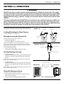
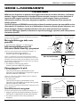
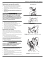
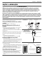
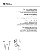
Locking/Unlocking the Rear Casters
•Referto Detail“A” ofFigure 3.1.
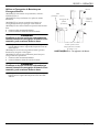
Raising/Lowering the Patient Lift
NOTE:Forthisprocedure,refertoDetail “B”.
•ToRaisethePatientLift:
Presstheup() buttononthehandcontrol.
NOTE:Ifthepatientlift isra isedtothehighestlevel,itmay be
necessarytopulldowngentlyontheliftarmsbefo r ethemastwill
begintolower.
Pull downgentlyonbotharmsatthesametimeto
avoidmaki ngtheliftunstable.
•ToLow erthePatientLift:
Pressthedownbutton() onthe handcontrol.
Closing/Opening the Legs
•ToClosethe Legs:
PulltheshifterhandleOUTandawayfromthestand‐uplift
andthentoyourLEFTuntilitLOCKSinthenotchofthe
bracket.
NOTE:Leftisdeterminedbystandingbehindthestand‐uplift
facingtowardsthefrontcasters.
•ToOpentheLegs:
Pulltheshifter
handleOUTandaw ayfromthestand‐uplift
andthento yourRIGHTuntilitLO CKSinthenotchof the
bracket.
NOTE:Rightisdeterminedbystandingbehindthestand‐uplift
facingtowardsthefrontcasters.
Using the Emergency Stop
NOTE:Forthisprocedure,refertoDetail “C”.
•PushtheREDemerge ncybuttonintostoptheliftarms
fromraisingorlowering.
•Toreset,rotatetheemerge ncybuttonclockwise.
FIGURE 3.1 Operating the Patient Lift
DETAIL “B” - HAND
CONTROL DETAILS
DETAIL “C” - EMERGENCY STOP
Down Button
Up Button
Hand Control
Emergency Button
Push in to stop,
turn clockwise
to reset.
Step Here
to Lock
Step Here
to Unlock
Locking
Lever
LOCKED
UNLOCKED
DETAIL “A”
RPS350-1ERPS350-1FR

SECTION 3—OPERATION
Stand Assist Patient Lift 12 Part No. 1078985
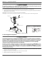
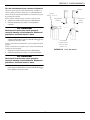
Activating a Mechanical Emergency
Release
Primary Emergency Release
NOTE:Forthisprocedure,refertoFIGURE 3.2.
NOTE:Thisprocedurewillbringtheb oomdownifthehandcontr ol
isnotfunctioningpr operly .
Toactiv atetheprimaryemergencyrelease,insertthetipofa
penintotheEmergencyDownhole() inthe controlbox.
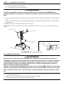
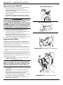
Secondary Emergency Release
NOTE:Forthisprocedure,refertoFIGURE 3.3.
NOTE:Allpatientliftactuato rsareequippedwithamechanical
emergencyrelease.Themechanicalreleasewillenabletheactuatorto
retractwithoutpower.
NOTE:Usetheprimaryemer gencyreleasefirstbeforeusingthe
secondaryemer gencyreleaseprocedur e.Thispr ocedur eshouldonly
beusedifthe
primaryemergencyreleaseprocedureisnotfunctioning
orisunreachable.
NOTE:TheliftMUSTbeunderaloadforthemechanicalreleaseto
function.
Toactiv atethesecondaryemergencyrelease,pulluponthe
REDemergencygripandpulldownontheboomatthesame
time.
Charging the Battery
Using a Power Cord to Charge the Battery
NOTE:Forthisprocedure,refertoFIGURE 3.2.
NOTE:ThisprocedureonlyappliestotheRPS350‐1FR.
CAUTION
The emergency stop MUST NOT be activated
- otherwise it will be impossible to charge the
battery. While charging takes place, the
patient lift cannot be used. DO NOT attempt
to move the patient lift without unplugging the
power cord from the wall outlet. DO NOT
attempt to use the patient lift if the battery
housing is damaged. Replace a damaged
battery housing before any further use.
1. Attachthepowercordtothecontrolbox.
2. Plugthepowercordintoasocketoutlet.
NOTE:Thebatterywillchargeinapproximately4hours.
Chargingmustbedoneinaroomwithgoodairventilation.
3. Disconnectthepowercordfromthesocketoutletafterthe
batteryhasbeenfullycharged.
FIGURE 3.2 Primary Emergency Release
FIGURE 3.3 Secondary Emergency Release
Emergency Down
Hole
Control Box
Emergency
Up Hole
Emergency Down
Hole
Control Box
Charger Cable
connects here
RPS350-1E
RPS350-1FR
RED Emergency Grip

SECTION 3—OPERATION
Part No. 1078985 13 Stand Assist Patient Lift
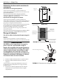
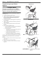
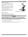
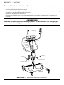
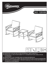
Using the Battery Charger to Charge the
Battery
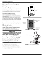
NOTE:Forthisprocedure,refertoFIGURE 3.4.
NOTE:Thispr ocedur eonlyappliestotheRPS350‐1E.
NOTE:Invacar erecommendsthebatteryberechargeddailyto
prolongbatterylife.
NOTE:Anaudiblealarmwillsoundwhenbatteryislow.
1. LiftUPonthehandleonthebac kofthebattery.
2. Liftthebatteryup
andaw ayfromthecont rolbox.
CAUTION
Make sure there is an audible click when
mounting battery on the battery charger.
Otherwise, injury or damage may occur.
3. Placethebatteryonthebatterycharger.Pushthetopofthe
batteryagainstthemountingbracketuntilthereisan
audibleclick.
NOTE:ThechargeLEDwillilluminate.Whencharged,theLED
willstopilluminating.
NOTE:Itwilltakeapproximatelyfourhourstochargeabatterythat
requiresafullcharge.
4. LiftUPonthehandleonthebac kofthebattery.
5. Liftthebatteryupandawayfromthebatterycharger.
CAUTION
Make sure there is an audible click when
mounting battery on the battery charger.
Otherwise, injury or damage may occur.
6. Placethebatteryonthecontr olbox.Pushthetopofthe
batteryagainstthemountingbracketuntilthereisan
audibleclick.
FIGURE 3.4 Using the Battery Charger to Charge the
Battery
Battery Charger
(STEP 3)
Control Box
(STEP 6)
An audible “click”
will be heard when
properly installed
(STEPS 3 and 6)
Handle
STEPS 1, 2, 4 and 5)
Battery

SECTION 4—LIFTING THE PATIENT
Stand Assist Patient Lift 14 Part No. 1078985
SECTION 4—LIFTING THE PATIENT
WARNING
DO NOT exceed the maximum weight limitation of 25 stone (350 lbs).
DO NOT attempt to any transfer without approval of the a Healthcare Professional.
ALWAYS keep hands and fingers clear of moving parts to avoid injury.
Use the sling that is recommended by the individual’s doctor, nurse or medical assistant for the
comfort and safety of the individual that is being lifted.
Individuals that use the standing patient sling MUST be able to support the majority of their own
weight, otherwise injury may occur.
The legs of the stand assist lift MUST be in the maximum open position and the shifter handle locked
in place for optimum stability and safety. If the patient is in a sling and it becomes necessary to move
through a narrow passage, close the legs of the stand-up lift only as long as it takes to move through
the passage. Once the stand-up lift is through the passage, return the legs of the stand-up lift to the
maximum open position and lock the shifter handle IMMEDIATELY.
DO NOT move the patient if the patient sling is not properly connected to the attachment points on
the patient lift. Check that the patient sling is properly connected to the attachment points BEFORE
lifting the patient.
During transfer, with the patient suspended in the patient sling, DO NOT roll the base of the patient
lift over any uneven surfaces that would cause the patient lift to become unstable.
Use the steering handle on the mast assembly at all times to push or pull the Stand Assist Lift.
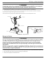
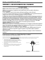
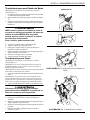
Positioning the Stand Assist Lift
NOTE:Forthisprocedure,refertoFIGURE 4.1.
NOTE:Refer toGeneralGuidelines
onpage 7befor epr oceed ingandobserveallwarningsindicated.
NOTE:Befor epositioningthelegsofthepatientliftunderabed,makesur e thatthe ar eaisclearofanyobstructions.
1. EnsurethelegsoftheStandAssistLiftareinthe
maximumopenposition.Ifnot,usetheshifterhandle
toopenthelegs.
2. P osition theStand AssistLiftusingthemasthandle.
3. PresstheDOWNbuttononthehandcontroltolowe rthe
liftarmsforeasyattachmenttothesling.
FIGURE 4.1 Hand Control Buttons
DOWN Button
UP Button
Hand Control

SECTION 4—LIFTING THE PATIENT
Stand Assist Patient Lift 15 Part No. 1078985
Lifting the Patient
WARNING
DO NOT exceed the maximum weight limitation of 25 stone (350 lbs).
Individuals that use the stand assist sling MUST be able to support the majority of their own weight,
otherwise injury may occur.
DO NOT move the patient if the sling is not properly attached to the attachment points on the Stand
Assist Lift. Make sure that the sling is properly attached BEFORE lifting the patient. If any
attachments are not properly in place, correct the problem. When the sling is elevated a few inches
off the stationary surface and before moving the patient, check again to make sure the sling and all
attachments are securely in place. If any problem is found, lower the patient back onto the stationary
surface and correct the problem - otherwise, injury or damage may occur.
Adjustments for safety and comfort should be made before moving the patient.
Use the sling that is recommended by the individual’s doctor, nurse or medical assistant for the
comfort and safety of the individual that is being lifted.
NOTE:Forthisprocedure,refertoFIGURE 4.2onpage16.
NOTE:RefertothepatientslingOwner’sManual,P/N1023891,formoreinformation.
NOTE:ThepatientMUSTbeinaseatedpositionfirst.Use theheadsectionofthebedtogetthepatientuprightthe nmovelegsovertheside
of
thebed.
1. Instructthepatienttoholdontothehan dgripsonbothsidesoftheStandAssistLift(Detail“A ”ofFIGURE 4.2).
2. Instructthepatienttoleanbackintothestandingortransfersling.
WARNING
Stand Assist Slings - Before lifting the patient, make sure the bottom edge of the stand assist sling is
positioned on the lower back of the patient and the patient’s arms are outside the sling.
Standing Slings - Before lifting the patient, make sure the bottom edge of the standing sling is at the
base of the spine and the patient’s arms are outside the sling.
Invacare does not recommend locking the rear casters of the Stand Assist Lift when lifting and trans-
ferring an individual. Doing so could cause the lift to tip and endanger the patient and assistants. Inva-
care recommends that the rear casters be left unlocked during lifting and transferring procedures to
allow the Stand Assist Lift to stabilize itself when the patient is initially lifted from and transferred to
a chair, bed or any stationary object.
3. Ensurethefollowing:
A. Thepatient’skneesare secureagainstthekneepad.
B. Thepatient’sfeetareproperlypositionedonthefootplate.
C. Slings:
• StandAssistSling‐thebottomed geofthestandassistslingispositionedonthe patient’slowerback.
• StandingSling‐thebottomedgeofthestandin gslingisatthe
baseofthepatient’sspine.
•EitherSlingStyle‐thepatient’sarmsareoutsidethesling.
D. Therearcastersareunlocked.
E. Thelegsareinthemaximumopenposition.

SECTION 4—LIFTING THE PATIENT
Part No. 1078985 16 Stand Assist Patient Lift
WARNING
If transferring a patient from a wheelchair, the wheelchair wheel locks MUST be in the locked posi-
tion before lowering the patient into the wheelchair. Otherwise, injury may occur.
4. Iftransferringfromawheelchair ,lockthewheellocksonthewheelchair (Detail“B”of FIGURE 4.2).
5. PresstheUParrowbuttonontheha ndcontroltoraisethepatientabovethesurface(bed,wheelchairorcommode).
NOTE:Thepatient’sweig htwillbesupportedbytheStandAssistLift.
NOTE:Thelowercenter
ofgravityprovidesstabilitymaki ngthepatientfeelmo resecureandthelifteasiertomove.
FIGURE 4.2 Lifting the Patient
Moving the Patient
WARNING
The legs of the Stand Assist Lift MUST be in the maximum open position for optimum stability
and safety. If the patient is in a sling and it becomes necessary to move through a narrow
passage, close the legs of the Stand Assist Lift only as long as it takes to move through the
passage. When the Stand Assist Lift is through the passage, return the legs to the maximum
open position.
DO NOT, during transfer of a patient suspended in the lift sling, roll caster base over uneven sur-
faces that would create an imbalance of the lift. This could cause the lift to tip over. Use the mast
handle at all times to push or pull the lift.
1. EnsurethelegsoftheStandAssistLiftareinthemaximumopenposition.Ifnot,usetheshifterhandletoopenthelegs.
2. MovetheStandAssistLiftawayfromthesurfacetheywereliftedfrom.
3. Slowlymovethepatienttothedesiredsurface.
Handgrip
Casters
Knee Pad
Foot Plate
DETAIL “A” - WHEEL LOCK
Wheel Lock
Mast Handle

SECTION 5—TRANSFERRING THE PATIENT
Stand Assist Patient Lift 17 Part No. 1078985
SECTION 5—TRANSFERRING THE PATIENT
WARNING
DO NOT attempt any transfer of a patient without the approval of a Healthcare Professional.
DO NOT move the patient if the sling is not properly connected to the attachment points of the
Stand Assist Lift. Check that the sling is properly connected to the attachment points prior to
lifting a patient. If any attachments are not properly in place, correct the problem. When the sling is
elevated a few inches off the stationary surface and before moving the patient, check again to make
sure that all sling attachments are secure. If any attachments are not properly in place, lower the
patient back onto the stationary surface and correct this problem - otherwise, injury or damage may
occur.
Adjustments for safety and comfort should be made before moving the patient.
Use the sling that is recommended by the individual’s doctor, nurse or medical assistant for the
comfort and safety of the individual that is being lifted.
Invacare does not recommend locking the rear casters of the Stand Assist Lift when lifting and
transferring an individual. Doing so could cause the lift to tip and endanger the patient and assistants.
Invacare recommends that the rear casters be left unlocked during lifting and transferring
procedures to allow the Stand Assist Lift to stabilize itself when the patient is initially lifted from and
transferred to a chair, bed or any stationary object.
The legs of the Stand Assist Lift MUST be in the maximum open position for optimum stability
and safety. If the patient is in a sling and it becomes necessary to move through a narrow
passage, close the legs of the Stand Assist Lift only as long as it takes to move through the
passage. When the Stand Assist Lift is through the passage, return the legs to the maximum
open position. If it is necessary to close the legs to maneuver the Stand Assist Lift under a bed,
close the legs only as long as it takes to position the Stand Assist Lift over the patient and lift the
patient off the surface of the bed. When the legs of the Stand Assist Lift are no longer under the
bed, return the legs to the maximum open position.
Be sure to check the sling attachments each time the sling is removed and replaced to ensure that it
is properly attached before the patient is removed from a surface.
Theuseofoneassistantisbasedontheevaluationofthehealthcareprofessionalforeachindividualcase.

SECTION 5—TRANSFERRING THE PATIENT
Part No. 1078985 18 Stand Assist Patient Lift
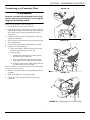
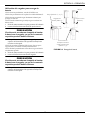
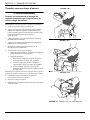
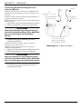
Transferring to a Commode Chair
WARNING
Invacare recommends locking the rear swivel
casters only when positioning or removing the
sling from around the patient.
NOTE:Forthisprocedure,refertoFIGURE 5.1.
1. Liftthepatientfromthesideofthebed.
2. PresstheUPbuttononthehandcontroltoelevatethe
patienthighenoughtoclearthearmsofthecommode
chair.TheirweightwillbesupportedbytheStand
AssistLift.
3. Guidethepatientonto
thecommodechair.Thismay
requiretwoassistants.
4. Pressthedownarrowbuttontolowerthepatientonto
thecommodechair.
5. LocktherearswivelcastersontheStandAssistLift.
6. Performoneofthefollowing:
•StandAssistSling‐unhookthestandassistsling
fromtheattachmentpointsonthelift.
•StandingSling‐
i. Unhookthestandingslingfromthebottom
attachmentpointsonthelift.
ii. Liftuponthepatient’sleg sand removethe
thighsupportsfromunderneaththepatient.
iii. Ifdesired,unhookthestandingslingfromthe
topattachmentpointsonthelift.
NOTE:Thepatientcanremainintheupperportionofthe
transfer
slingwhileusingthecommode.
7. Instructorassistthepatientinliftingtheirfeetoffthe
footplate.
8. Removetheslingfromaroundthepatient.
9. Unlockthecastersandpulltheliftawayfromthe
commode.
FIGURE 5.1 Transferring to a Commode Chair
DETAIL “A”
DETAIL “B”
DETAIL “C”

SECTION 5—TRANSFERRING THE PATIENT
Stand Assist Patient Lift 19 Part No. 1078985
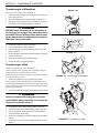
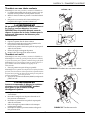
Transferring to a Wheelchair
NOTE:Forthisprocedure,refertoFIGURE 5.2.
1. Ensurethelegsoftheliftwiththepatientintheslingare
intheopenposition.
2. Movethewheelchairintoposition.RefertoDe tail“A ”.
3. Engagetherearwheellocksofthe wheelchairtoprev ent
mov ement ofthewheelchair.RefertoDetail“B”.
WARNING
DO NOT place the patient in the wheelchair if
the locks are not engaged. The wheelchair wheel
locks MUST be in a locked position before lower-
ing the patient into the wheelchair for transport.
Otherwise, injury may result.
4. P osition thepatientoverthewhee lchai r.
5. Lowerthepatientintothewheelchair.
6. Unhooktheslingfromallattachmentpointsonthelift.
RefertoDetail“C”.
7. Instructpatienttolifttheirfeetoffthefootplate.Assistthe
patientifnecessary.
8. Removetheslingfr omaroundthepatient.
9. Pulltheliftawayfromthe
wheelchair.
Transferring to a Bed
NOTE:Forthisprocedure,refertoFIGURE 5.3.
NOTE:Thelowercenterofgravityprovidesstabilitymaki ngthe
patientfeelmoresecureandthelifteasiertomove.
NOTE:Theliftarmswi llstayinpositionuntil theDOWNbutton
onthehandcontr olispres sed.
1. P osition thepatientasfarov erthe
bedaspossible.
NOTE:Ifpatientisbeingtransferredfr omasurfacethatislower
thanthebed,raisethepatientabovethesurfaceofthebed.Thepatient
shouldbeelevatedjusthighenoughtoclearthebedwiththeirweight
fullysuppor tedbythelift.
2. PresstheDOWNbuttonand
lowerthepatientontothebed.
WARNING
Invacare recommends locking the rear swivel
casters ONLY when positioning or removing the
sling from around the patient.
3. Locktherearswivelcaste rsontheStandAssistLift.
4. Unhooktheslingfromallattachmentpointsonthelift.
5. Instructthepatienttolifttheirfeetoffofthefootplate.
Assistthepatientifnecessary.
6. Removethestandingorstandassistslingfromaroundthe
patient.
7. Unlocktherearswiv elcastersand
pulltheliftawayfrom
thebed.
FIGURE 5.2 Transferring to a Wheelchair
FIGURE 5.3 Transferring to a Bed
DETAIL “A”
DETAIL “B”
DETAIL “C”

SECTION 6—TROUBLESHOOTING
Stand Assist Patient Lift 20 Part No. 1078985
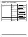
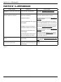
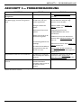
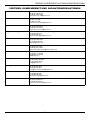
SECTION 6—TROUBLESHOOTING
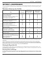
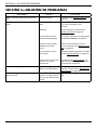
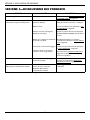
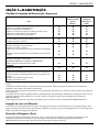
NOTE:Ifproblemsarenotremediedbythesuggestedmeans,pleasecontactyourdealerorInvacare.
SYMPTOMS FAULTS SOLUTION
Noisy or dry sound from pivots. Needs lubrication. Refer to Lubricating the Lift on page 22.
Electric actuator fails to lift when button is
pressed.
Hand-control or actuator
connector loose.
Battery low.
RED emergency stop button
pressed IN.
Battery not connected properly
to control box.
The connecting terminals are
damaged.
Electric actuator in need of ser-
vice or load is too high.
Check the hand control and actuator con-
nections. Re-connect as necessary.
Charge batteries. Refer to Using the Battery
Charger to Charge the Battery on page 13.
Rotate RED emergency stop button
CLOCKWISE until it pops out.
Reconnect the battery to the control box.
Refer to Using the Battery Charger to
Charge the Battery on page 13.
Replace the battery pack. Refer to Using the
Battery Charger to Charge the Battery on
page 13.
Refer to Adjusting the Base
on page 22.
Contact Dealer if service is required.
Unusual noise from actuator. Actuator is worn or damaged
or spindle is bent.
Replace the actuator or contact Dealer.
Refer to Replacing the Electric Actuator
on
page 23.
Lift arms will not lower from the uppermost
position.
Lift arms require a minimum
weight load to lower from the
uppermost position.
Pull down slightly on the lift arms.
Seite wird geladen ...
Seite wird geladen ...
Seite wird geladen ...
Seite wird geladen ...
Seite wird geladen ...
Seite wird geladen ...
Seite wird geladen ...
Seite wird geladen ...
Seite wird geladen ...
Seite wird geladen ...
Seite wird geladen ...
Seite wird geladen ...
Seite wird geladen ...
Seite wird geladen ...
Seite wird geladen ...
Seite wird geladen ...
Seite wird geladen ...
Seite wird geladen ...
Seite wird geladen ...
Seite wird geladen ...
Seite wird geladen ...
Seite wird geladen ...
Seite wird geladen ...
Seite wird geladen ...
Seite wird geladen ...
Seite wird geladen ...
Seite wird geladen ...
Seite wird geladen ...
Seite wird geladen ...
Seite wird geladen ...
Seite wird geladen ...
Seite wird geladen ...
Seite wird geladen ...
Seite wird geladen ...
Seite wird geladen ...
Seite wird geladen ...
Seite wird geladen ...
Seite wird geladen ...
Seite wird geladen ...
Seite wird geladen ...
Seite wird geladen ...
Seite wird geladen ...
Seite wird geladen ...
Seite wird geladen ...
Seite wird geladen ...
Seite wird geladen ...
Seite wird geladen ...
Seite wird geladen ...
Seite wird geladen ...
Seite wird geladen ...
Seite wird geladen ...
Seite wird geladen ...
Seite wird geladen ...
Seite wird geladen ...
Seite wird geladen ...
Seite wird geladen ...
Seite wird geladen ...
Seite wird geladen ...
Seite wird geladen ...
Seite wird geladen ...
Seite wird geladen ...
Seite wird geladen ...
Seite wird geladen ...
Seite wird geladen ...
Seite wird geladen ...
Seite wird geladen ...
Seite wird geladen ...
Seite wird geladen ...
Seite wird geladen ...
Seite wird geladen ...
Seite wird geladen ...
Seite wird geladen ...
Seite wird geladen ...
Seite wird geladen ...
Seite wird geladen ...
Seite wird geladen ...
Seite wird geladen ...
Seite wird geladen ...
Seite wird geladen ...
Seite wird geladen ...
Seite wird geladen ...
Seite wird geladen ...
Seite wird geladen ...
Seite wird geladen ...
Seite wird geladen ...
Seite wird geladen ...
Seite wird geladen ...
Seite wird geladen ...
Seite wird geladen ...
Seite wird geladen ...
Seite wird geladen ...
Seite wird geladen ...
Seite wird geladen ...
Seite wird geladen ...
Seite wird geladen ...
Seite wird geladen ...
Seite wird geladen ...
Seite wird geladen ...
Seite wird geladen ...
Seite wird geladen ...
Seite wird geladen ...
Seite wird geladen ...
Seite wird geladen ...
Seite wird geladen ...
Seite wird geladen ...
Seite wird geladen ...
Seite wird geladen ...
Seite wird geladen ...
Seite wird geladen ...
Seite wird geladen ...
Seite wird geladen ...
Seite wird geladen ...
Seite wird geladen ...
Seite wird geladen ...
Seite wird geladen ...
Seite wird geladen ...
Seite wird geladen ...
Seite wird geladen ...
Seite wird geladen ...
Seite wird geladen ...
Seite wird geladen ...
Seite wird geladen ...
Seite wird geladen ...
Seite wird geladen ...
Seite wird geladen ...
Seite wird geladen ...
Seite wird geladen ...
Seite wird geladen ...
-
 1
1
-
 2
2
-
 3
3
-
 4
4
-
 5
5
-
 6
6
-
 7
7
-
 8
8
-
 9
9
-
 10
10
-
 11
11
-
 12
12
-
 13
13
-
 14
14
-
 15
15
-
 16
16
-
 17
17
-
 18
18
-
 19
19
-
 20
20
-
 21
21
-
 22
22
-
 23
23
-
 24
24
-
 25
25
-
 26
26
-
 27
27
-
 28
28
-
 29
29
-
 30
30
-
 31
31
-
 32
32
-
 33
33
-
 34
34
-
 35
35
-
 36
36
-
 37
37
-
 38
38
-
 39
39
-
 40
40
-
 41
41
-
 42
42
-
 43
43
-
 44
44
-
 45
45
-
 46
46
-
 47
47
-
 48
48
-
 49
49
-
 50
50
-
 51
51
-
 52
52
-
 53
53
-
 54
54
-
 55
55
-
 56
56
-
 57
57
-
 58
58
-
 59
59
-
 60
60
-
 61
61
-
 62
62
-
 63
63
-
 64
64
-
 65
65
-
 66
66
-
 67
67
-
 68
68
-
 69
69
-
 70
70
-
 71
71
-
 72
72
-
 73
73
-
 74
74
-
 75
75
-
 76
76
-
 77
77
-
 78
78
-
 79
79
-
 80
80
-
 81
81
-
 82
82
-
 83
83
-
 84
84
-
 85
85
-
 86
86
-
 87
87
-
 88
88
-
 89
89
-
 90
90
-
 91
91
-
 92
92
-
 93
93
-
 94
94
-
 95
95
-
 96
96
-
 97
97
-
 98
98
-
 99
99
-
 100
100
-
 101
101
-
 102
102
-
 103
103
-
 104
104
-
 105
105
-
 106
106
-
 107
107
-
 108
108
-
 109
109
-
 110
110
-
 111
111
-
 112
112
-
 113
113
-
 114
114
-
 115
115
-
 116
116
-
 117
117
-
 118
118
-
 119
119
-
 120
120
-
 121
121
-
 122
122
-
 123
123
-
 124
124
-
 125
125
-
 126
126
-
 127
127
-
 128
128
-
 129
129
-
 130
130
-
 131
131
-
 132
132
-
 133
133
-
 134
134
-
 135
135
-
 136
136
-
 137
137
-
 138
138
-
 139
139
-
 140
140
-
 141
141
-
 142
142
-
 143
143
-
 144
144
-
 145
145
-
 146
146
-
 147
147
-
 148
148


Invacare RPS350–1FR Benutzerhandbuch
- Typ
- Benutzerhandbuch
- Dieses Handbuch eignet sich auch für
in anderen Sprachen
- English: Invacare RPS350–1FR User manual
- français: Invacare RPS350–1FR Manuel utilisateur
- español: Invacare RPS350–1FR Manual de usuario
- italiano: Invacare RPS350–1FR Manuale utente
- português: Invacare RPS350–1FR Manual do usuário
Verwandte Artikel
-
Invacare RPS350-1E Benutzerhandbuch
-
-
-
-
-
-
Invacare Fox Benutzerhandbuch
-
-
Invacare XPO2 Benutzerhandbuch
-
Andere Dokumente
-
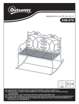 Outsunny 84B-078 Iron Rocking Bench Benutzerhandbuch
-
Outsunny 862-005CF Benutzerhandbuch
-
 Joerns Oxford® M78287 Bedienungsanleitung
-
 Joerns Oxford® F27178 Bedienungsanleitung
-
 Outsunny 863-120V00KK Benutzerhandbuch
-
 Outsunny 860-279V00GG Benutzerhandbuch
-
 Outsunny 867-138V00GG Benutzerhandbuch
-
 Outsunny 860-221 Assembly Instructions
-
Joerns Hoyer Advance Bedienungsanleitung
-
Joerns Healthcare Oxford Comfort Sling Benutzerhandbuch


