SICK TR4 T-junction TR4-AK004C Mounting instructions
- Typ
- Mounting instructions

M O N T A G E A N L E I T U N G
TR4 T-Stück
TR4-AK004C
D
SICK AG • Industrial Safety Systems
ErwinSick-Straße 1
D-79183 Waldkirch • www.sick.com
8015436/XA24/2013-07-15 • RV/XX
Printed in Germany (2013-07) • Alle Rechte
vorbehalten • Irrtümer und Änderungen
vorbehalten
1 Über dieses Dokument
Diese Montageanleitung ist eine Original-
Montageanleitung.
4 Montage
Verhindern Sie eine Überbrückung der Sicherheitsschalter!
Wenn Sie die TR4-T-Stücke zur Reihenschaltung verwenden, dann müssen Sie die Anschlussleitun-
gen sowie die Endstecker so montieren, dass ein Überbrücken der
Transponder-Sicherheitsschalter
TR4 Direct nicht möglich ist.
5 Technische Daten
Allgemeine Daten
Umgebungstemperatur –25 bis +90 °C
Werkstoffe
Gehäuse PUR
Kontaktträger PUR
Kontakt Kupferlegierung
Kontaktoberfläche Au/Ni
Mutter/Schraubhülse CUZn mit Ni-Oberfläche
Mechanische Daten
Schutzart IP 68
1)
Elektrische Daten
Betriebsspannung 30 V DC
Bemessungsstrom 2 A
Hinweis:
Nicht unter Spannung trennen!
6 Bestelldaten
Artikel Artikelnummer
TR4-AK004C 5325889
1)
Nur im verschraubten Zustand mit den dazugehörigen Gegenstücken.
M O U N T I N G I N S T R U C T I O N S
TR4 T-junction
TR4-AK004C
GB
SICK AG • Industrial Safety Systems
ErwinSick-Straße 1
D-79183 Waldkirch • www.sick.com
8015436/XA24/2013-07-15 • RV/XX
Printed in Germany (2013-07) • All rights
reserved • Subject to change without notice
1 About this document
These mounting instructions are original mounting
instructions.
4 Mounting
Prevent jumpering of the safety switches!
When using TR4-T-junctions for series connection, the connecting cables and the end plug
have to be installed in such a way that the transponder safety switches TR4 Direct cannot be
jumpered.
5 Technical data
General data
Ambient temperature –25 to +90 °C
Materials
Housing PUR
Insert PUR
Contact Copper alloy
Contact finish Au/Ni
Coupling nut CUZn (brass), Ni plated
Mechanical data
Degree of protection IP 68
2)
Electrical data
Operating voltage 30 V DC
Rated connector current 2 A
Note:
Remove power before disconnection!
6 Ordering information
Part Part number
TR4-AK004C 5325889
2)
Only with inserted nuts with the belonging complements.
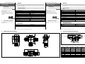
2 Maßbild/Dimensional drawing
Fig. 1: Maßbild TR4 T-Stück/dimensional drawing TR4 T-junction
3 Interne Verdrahtung/Internal wiring
Fig. 2: Interne Verdrahtung TR4 T-Stück/internal wiring TR4 T-junction
Bezeichnung
Stecker
M12, 5polig
Buchse
M12, 8polig
Buchse
M12, 5polig
Beschreibung
Designation
Conn. male
M12, 5pin
Conn. female
M12, 8pin
Conn. female
M12, 5pin
Description
Out Aux – 1 – Aux output (not safe)
+24 V DC 1 2 1 Voltage supply 24 V DC
n. v. 5 3 5 Not connected
In B – 4 4 Enable input for channel B
Out A 2 5 – Safety output A
Out B 4 6 – Safety output B
0 V 3 7 3 Voltage supply 24 V DC
In A – 8 2 Enable input for channel A
Tab. 1: Pin-Belegung TR4 T-Stück/Pin assignment TR4 T-junction
(mm)
17
30,5
16,0
1,5
45,2
10,4
6,5
4,5×45°
4×45°
12,9
8,0
1,5×45
4,5
12,5
56,4
12,5
12,5
26,5
23,5
45°
M12-Stecker
Male M12
M12-Buchse
Female M12
M12-Buchse/female M12
-
 1
1
