
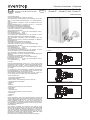
Ausschreibungstext:
Oventrop Verschraubung „Combi 4“/„Combi C“
mit proportionaler, reproduzierbarer Feineinstellung für den Ein-
satz in Warmwasser-Zentralheizungen und Kühlwasserkreis-
läufen.
Zum Voreinstellen, Absperren, Füllen und Entleeren des Heiz-
körpers.
Rotguss/Messing-Armatur, vernickelt („Combi C“ - verchromt),
Ventilkegel mit EPDM O-Ring-Abdichtung.
Schutzkappe mit zusätzlicher Dichtfunktion.
Anschluss für Entleerungs- und Füllwerkzeug.
Anschluss für Gewinde- und Klemmverbindungen.
Einbaumaße nach DIN 3842.
Betriebstemperatur ts: 2 °C bis 120 °C (kurzzeitig bis 130 °C)
max. Betriebsdruck ps: 10 bar
Oventrop Verschraubung „Combi 3“
mit proportionaler Feineinstellung für den Einsatz in Warm-
wasser-Zentralheizungen und Kühlwasserkreisläufen.
Zum Voreinstellen, Absperren, Füllen und Entleeren des Heiz-
körpers.
Rotguss/Messing-Armatur, vernickelt, Ventilkegel mit EPDM O-
Ring-Abdichtung.
Schutzkappe mit zusätzlicher Dichtfunktion.
Anschluss für Entleerungs- und Füllwerkzeug.
Anschluss für Gewinde-, Klemm- und Pressverbindungen.
Einbaumaße nach DIN 3842.
Betriebstemperatur ts: 2 °C bis 120 °C (kurzzeitig bis 130 °C)
max. Betriebsdruck ps: 10 bar
Oventrop Verschraubung „Combi 2“
mit proportionaler Feineinstellung für den Einsatz in Warm-
wasser-Zentralheizungen und Kühlwasserkreisläufen.
Zum Voreinstellen und Absperren des Heizkörpers.
Messing-Armatur, vernickelt, Ventilkegel mit EPDM O-Ring-Ab-
dichtung.
Schutzkappe mit zusätzlicher Dichtfunktion.
Anschluss für Gewinde-, Klemm- und Lötverbindungen.
Einbaumaße nach DIN 3842.
Betriebstemperatur t s: 2 °C bis 120 °C (kurzzeitig bis 130 °C)
max. Betriebsdruck ps: 10 bar
Funktion:
Oventrop Verschraubungen „Combi 4, 3, 2 und C“ werden in den
Heizkörper-Rücklauf eingebaut, wobei auf die Zu gäng lichkeit der
Entleerung bei der „Combi 4, 3 und C“ geachtet werden muss.
Sie ermöglichen die Demontage von Heizkör pern ohne Entleeren
der Anlage.
Zur Durchführung des hydraulischen Abgleichs innerhalb der
Heizungsanlage kann eine Voreinstellung zur Veränderung de s
Durchflusswiderstandes vorgenommen werden.
Das Entleeren und Füllen des Heizkörpers (nur bei „Combi 4, 3
und C“) erfolgt durch ein Entleerungs- und Füllwerkzeug.
Anwendungsbereich:
- Warmwasser-Zentralheizungen
- Kühlwasserkreisläufe
„Combi 4 und C“ Verschraubung mit den Funktionen:
- reproduzierbares Voreinstellen
- Absperren
- Füllen
- Entleeren
„Combi 3“ Verschraubung mit den Funktionen:
- Voreinstellen
-Absperren
- Füllen/Entleeren
„Combi 2“ Verschraubung mit den Funktionen:
- Voreinstellen
- Absperren
Hinweis:
Durch Verwendung einer Klemmringverschraubung können die
Oventrop Verschraubungen auch bei der Installation mit Oventrop
„Copipe“ Mehrschicht-Verbundrohr (14 und 16 mm) sowie Kup-
ferrohr ein gesetzt werden (10 - 22 mm). Die Ausführungen mit
G 3⁄4AG eignen sich zusätzlich für den Anschluss von Präzisions-
stahl-, Edelstahl-, sowie Kunst stoff rohr und dem Oventrop „Copi-
pe“ Mehrschicht-Verbundrohr.
Pressanschluss:
Zum direkten Anschluss von Kupferrohr nach DIN EN 1057/
DVGW GW 392, Edelstahlrohr nach DIN EN 10088/DVGW GW
541 und dünnwandiges C-Stahlrohr (Werkstoff-Nr. E 195/1.0034)
nach DIN EN 10305-3. Die Pressanschlüsse sind unverpresst un-
dicht. Zum Verpressen ausschließlich Pressbacken mit den Ori-
ginalkonturen SANHA (SA), Geberit-Mapress (MM) oder Viega
(Profipress) in der passenden Größe verwenden.
Die Verarbeitung muss gemäß der Einbauanleitung erfolgen.
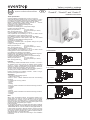
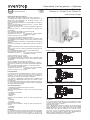
Verschraubung „Combi 4“
Schnitte:
„Combi 4 und C“ Eckform mit Innengewinde EN 10226-1
„Combi 2“ Eckform mit Innengewinde EN 10226-1
„Combi 3“ Eckform mit Innengewinde EN 10226-1
Das Qualitätsmanagementsystem von
Oventrop ist gemäß DIN EN ISO 9001
zertifiziert.
Verschraubungen „Combi 4“,
„Combi 3“, „Combi 2“ und „Combi C“
Premium Armaturen + Systeme
Einbauanleitung
DE

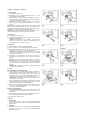
„Combi 4“ / „Combi 3“ / „Combi C“
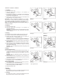
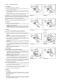
1 Voreinstellen:
1.1 Schutzkappe abschrauben.
1.2 Ventilkegel mit dem Sechskantschlüssel SW 4 (1) durch
Rechtsdrehen schließen (Bild 1).
1.3 Nun Ventilkegel mit dem Sechskantschlüssel SW 4 (1) ent-
sprechend den lt. Diagramm gewählten Umdrehungen durch
Linksdrehen voreinstellen (Bild 2).
1.4 Zuletzt Hohlschraube mit Schraubendreher durch Rechts-
drehen bis zum Anschlag schrauben (Bild 3, nur „Combi 4
und C“).
Wichtig: Bei nachträglicher Veränderung der Voreinstellung sollte
erst mit dem Schraubendreher (Bild 3) durch kurze Links-
drehung die Hohlschraube gelöst werden. Dann Änderung der
Voreinstellung mit dem Sechskantschlüssel SW 4 (1).
Hinweis: Die einmal gewählte Voreinstellung wird auch beim Ent-
leeren oder Absperren des Heizkörpers nicht verändert.
2 Absperren:
2.1 Schutzkappe abschrauben.
2.2 Ventilkegel mit Sechskantschlüssel SW 4 (1) durch Rechts-
drehen schließen (Bild 4).
Achtung: Hohlschraube nicht verdrehen, da sonst beim
Öffnen der Armatur die gewählte Voreinstellung nicht
mehr gegeben ist (nur „Combi 4 und C“).
3 Entleeren:
3.1 Regulierventil am Heizkörpervorlauf schließen.
3.2 Die „Combi 4/3/C“ wie in Punkt 2 beschrieben absperren.
3.3 Mit dem Sechskantschlüssel SW 10 (1) durch Linksdrehen
den Einsatz lockern (max. 1⁄4Gewindegang) (Bild 5).
Achtung: Die Hohlschraube muss soweit eingeschraubt
sein, dass der Sechskantschlüssel SW 10 min. 4 mm tief
eingesteckt werden kann.
3.4 Entleerungs- und Füllwerkzeug (2) auf die „Combi 4/3/C“
Verschraubung aufschrauben und Schlauch befestigen
(Bild 6).
Achtung: Druckschraube SW 19 dicht anziehen (max. 10 Nm).
3.5 Entlüftungsschraube am Heizkörper öffnen. Sechskant-
schlüssel SW 10 (1) auf Entleerungs- und Füllwerkzeug (2)
aufsetzen und durch Linksdrehen den Heizkörper entleeren
(Bild 6).
Achtung: Beim Füllen und Entleeren ist ein Differenzdruck
von maximal 4 bar zulässig.
4 Füllen:
über die Entleer- und Füllvorrichtung
4.1 Ist der Heizkörper vorher über das Entleerungs- und Füllwerk-
zeug (2) entleert worden, brauchen keine Veränderungen an
dem Werkzeug oder der Armatur vorgenommen werden. Der
Heizkörper kann nun über den angeschlossenen Schlauch
befüllt werden (Heizkörper muss nun entlüftet werden).
Achtung: Beim Füllen und Entleeren ist ein Differenzdruck
von maximal 4 bar zulässig.
4.2 Nach dem Befüllen den Sechskantschlüssel SW 10 (1) wieder
auf das Entleerungs- und Füllwerkzeug (2) aufsetzen und den
Einsatz durch Rechtsdrehen schließen (Bild 7).
4.3 Entleerungs- und Füllwerkzeug (2) von der Armatur abschrau-
ben und mit Sechskantschlüssel SW 10 (1) den Einsatz mit
max. 10 Nm nachziehen (Bild 8).
über das Heizungssystem
4.4 Mit Sechskantschlüssel SW 10 (1) durch Rechtsdrehen des
Einsatzes die Armatur schließen und mit max. 10 Nm anzie-
hen (Bild 8).
4.5 Mit Sechskantschlüssel SW 4 (1) den Ventilkegel durch Links-
drehen aufdrehen (Bild 2). Heizkörper entlüften.
4.6 Kappe wieder aufschrauben.
„Combi 2“
1 Voreinstellen:
Die Voreinstellung bei der „Combi 2“ Verschraubung erfolgt wie
bei der „Combi 4 und C“, jedoch mit Sechskantschlüssel SW6
(siehe Punkt 1).
2 Absperren:
Das Absperren der „Combi 2“ Verschraubung erfolgt ebenfalls
wie bei der „Combi 4 und C“, jedoch mit Sechskantschlüssel
SW6 (siehe Punkt 2).
Bild 1 Bild 2
Bild 4
Bild 6
Entleeren
Bild 8
Bild 3
Bild 5
Bild 7

L2
L2
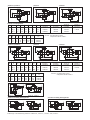
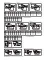
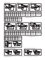
„Combi 4“/„Combi C“ „Combi 3“ „Combi 2“
DN D
D
L
L
t
t
D1
D1
L1
L1
L3
L3
„Combi 4“
vernickelt
„Combi 2“
roh
„Combi 3“
vernickelt „Combi 2“
vernickelt
Eckform mit Innengewinde
Eckform mit Lötanschluss
10
15
20
Rp 3⁄8
Rp 1⁄2
Rp 3⁄4
R 3⁄8
R 1⁄2
R 3⁄4
52
58
66
22
26
29
47,5
52,5
58,5
43,5
48,5
54,5
10,1
13,2
14,5
1090661
1090662
1090663
1090361
1090362
1090363
1091061
1091062
1091063
L2
DN tLD D1L1L3„Combi 4“
vernickelt „Combi 3“
vernickelt „Combi 2“
vernickelt
Durchgangsform mit Innengewinde
10
15
20
Rp 3⁄8
Rp 1⁄2
Rp 3⁄4
R 3⁄8
R 1⁄2
R 3⁄4
75
80
91
51,5
53,5
62,0
34,5
34,5
34,5
30,5
30,5
30,5
10,1
13,2
14,5
1090761
1090762
1090763
1090461
1090462
1090463
1091161
1091162
1091163
12
12
15
52
54
58
22
22
26
47,5
47,5
-
43,5
43,5
48
10
10
12
1091251
1091252
1091253
R 3⁄8
R 1⁄2
R 1⁄2
L2
DLSW
t
D1L1L3„Combi 2“
roh
Durchgangsform mit Lötanschluss
„Combi 4“ beidseitig Außengewinde „Combi 2“ beidseitig Außengewinde
12
12
15
75
77
80
51,5
53,5
53,5
34
34
-
30
30
30
10
10
12
27
27
30
1091351
1091352
1091353
R 3⁄8
R 1⁄2
R 1⁄2
Hinweis: Die Gewinde R und Rp
entsprechen der EN 10226-1.
Hinweis: Die Gewinde R und Rp
entsprechen der EN 10226-1.
Artikel-Nr. 1090672
Entleerungs- und Füllwerkzeug Artikel-Nr. 1090551 für „Combi 4“, „Combi 3“ und „Combi C“
Artikel-Nr. 1090772 Artikel-Nr. 1091072 Artikel-Nr. 1091172
L2
L1
t
D1
D
LL
t
L1
L3
D1
D
L
D
D1
t
L1
L2
D1
L2
t L1
L
D
L3
D
D1
t L1
L
D
L
L1t
L2
D1
EN 10226-1
EN 10226-1
80
53.5
9.5
34
G 3/4
R 1/2
„Combi 3“ mit Pressanschluss
Artikel-Nr. 1090374 Artikel-Nr. 1090474
72
46
18
Ø15
58
R1/2
EN 10226-1
34
Ø15
18 53.5
100
R1/2
EN 10226-1
30
G 3/4
R 1/2
9.5
53.5
80
EN 10226-1
EN 10226-1
„Combi C“
verchromt
–
1164554
–
„Combi 4“/„Combi C“ „Combi 3“ „Combi 2“
„Combi C“
verchromt
–
1165554
–

Technische Änderungen vorbehalten.
109036180 03/2021
OVENTROP GmbH & Co. KG
Paul-Oventrop-Straße 1
D-59939 Olsberg
Telefon +49 (0)29 62 82-0
Telefax +49 (0)29 62 82-400
E-Mail [email protected]
Internet www.oventrop.com
Eine Übersicht der weltweiten Ansprechpartner finden Sie unter
www.oventrop.de.
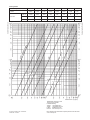
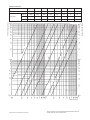
Leistungsdaten:
Voreinstellung
kv-Wert
Zeta-Wert
DN 10
DN 15
DN 20
0,25 0,5 0,75 1,5
12
34
0,060
10460
28070
93250
0,126
2370
6370
21150
0,190
1040
2780
9300
0,250
600
1620
5370
0,420
220
590
1900
0,819
56
150
500
1,236
25
66
220
1,700
13
35
116
Massenstrom qm[kg/h]
Druckverlust ∆p [mbar]
Druckverlust ∆p [Pascal]

Tender specification:
Oventrop radiator lockshield valve “Combi 4”/“Combi C”
with proportional fine presetting with memory position for use in
hot water central heating systems and for chilled water circuits.
For presetting, isolating, filling and draining of the radiator.
Made of bronze/brass, nickel plated (“Combi C” - chrome
plated), valve disc with EPDM O-ring seal.
Protection cap with additional sealing function.
Connection for service tool.
Suitable for threaded pipes or compression fittings.
Lengths according to DIN 3842.
Working temperature ts: 2 °C up to 120 °C
(for short periods up to 130°C)
Max. working pressure ps: 10 bar
Oventrop radiator lockshield valve “Combi 3”
with proportional fine presetting for use in hot water central
heating systems and for chilled water circuits.
For presetting, isolating, filling and draining of the radiator.
Made of bronze/brass, nickel plated, valve disc with EPDM
O-ring seal.
Protection cap with additional sealing function.
Connection for service tool.
Suitable for threaded pipes, compression fittings and press
connection.
Lengths according to DIN 3842.
Working temperature ts: 2 °C up to 120 °C
(for short periods up to 130°C)
Max. working pressure ps: 10 bar
Oventrop radiator lockshield valve “Combi 2”
with proportional fine presetting for use in hot water central
heating systems and for chilled water circuits.
For presetting and isolating of the radiator.
Made of brass, nickel plated, valve disc with EPDM O-ring seal.
Protection cap with additional sealing function.
Suitable for threaded or solder pipes or compression fittings.
Lengths according to DIN 3842.
Working temperature ts: 2 °C up to 120 °C
(for short periods up to 130°C)
Max. working pressure ps: 10 bar
Function:
The Oventrop radiator lockshield valves “Combi 4, 3, 2 and C”
are installed in the return pipe of the radiator. When installing
“Combi 4, 3 and C”, please ensure that the draining facility for
draining the radiator is accessible. This will allow the removal of
radiators without the necessity to drain the system.
To carry out the hydronic balancing with the heating system, a
presetting can be made to alter the flow resistance.
Draining and filling of the radiator (“Combi 4, 3 and C” only) is
carried out using the service tool.
Application:
- Hot water central heating systems
- Chilled water circuits
“Combi 4 and C” radiator lockshield valve with the following
functions:
- Presetting with memory position
- Isolating
- Filling
- Draining
“Combi 3” radiator lockshield valve with the following functions:
- Presetting
- Isolating
- Filling
- Draining
“Combi 2” radiator lockshield valve with the following functions:
- Presetting
- Isolating
Note:
When using compression fittings, the Oventrop radiator lock-
shield valves can also be used in installations with Oventrop
composition pipe “Copipe” (14 and 16 mm) as well as copper
pipe (10-22 mm). The models with G 3⁄4male thread can also be
used for precision steel, stainless steel and plastic pipes as well
as the Oventrop composition pipe “Copipe”.
Press connection:
For the direct connection of copper pipes according to DIN EN
1057/DVGW GW 392, stainless steel pipes according to DIN EN
10088/DVGW GW 541 and thin-walled C-steel pipe(material no.
E 195/1.0034) according to DIN EN 10305-3. Pressing must be
carried out to tighten the connection. Only use press jaws with
the original contours SANHA (SA), Geberit- Mapress (MM) or
Viega (Profipress) in corresponding size.
Processing must be carried out according to the installation
instructions.
Radiator lockshield valve “Combi 4”
Cut illustrations:
“Combi 4 and C” angle pattern with female thread according
to EN 10226-1
“Combi 2” angle pattern with female thread according
to EN 10226-1
“Combi 3” angle pattern with female thread according
to EN 10226-1
The Oventrop Quality Management
System is certified to DIN EN ISO 9001. Radiator lockshield valves “Combi 4”,
“Combi 3”, “Combi 2” and “Combi C”
Valves, controls + systems
Installation instructions
EN

“Combi 4” / “Combi 3” / “Combi C”
1 Presetting:
1.1 Remove protection cap.
1.2 Close the valve disc by turning a 4 mm spanner (1)
clockwise (drawing 1).
1.3 The preset the valve disc by turning the 4 mm spanner (1)
anticlockwise according to the number of turns selected
from the flow chart (drawing 2).
1.4 Finally, using a screwdriver, turn the lock nut clockwise until
stop (drawing 3, only “Combi 4 and C”).
Important: In case of subsequent modification of the preset-
ting, the lock nut should first be unscrewed by turning a screw-
driver (drawing 3) slightly anticlockwise. Afterwards the preset-
ting can be changed with the help of the 4 mm spanner (1).
Note: The chosen presetting will not be changed by draining or
isolating the radiator.
2 Isolating:
2.1 Remove protection cap.
2.2 Close the valve disc by turning a 4 mm spanner (1)
clockwise (drawing 4).
Attention: Do not twist the lock nut as otherwise the chosen
presetting is no longer given when opening the valve (only
“Combi 4 and C”).
3 Draining:
3.1 First close the thermostatic radiator valve in the flow pipe.
3.2 Isolate the “Combi 4/3/C” as described above (point 2).
3.3 Loosen the valve insert by turning a 10 mm spanner (1)
anticlockwise (max. 1⁄4thread)) (drawing 5).
Attention: The lock nut has to be screwed in sufficiently so
that the 10 mm spanner can be inserted up to 4 mm at least.
3.4 Fit the service tool (2) to the “Combi 4/3/C” and connect a
hose (drawing 6).
Note: Tighten the 19 mm compression nut closely (max. 10 Nm).
3.5 Open the vent screw at the radiator. Fit the 10 mm spanner
(1) to the service tool (2) and drain the radiator by turning
anticlockwise (drawing 6).
Attention: The max. differential pressure during filling and
draining is 4 bar.
4 Filling:
by using the service tool
4.1 If the radiator was just drained with the service tool (2), no
modifications to the tool or the valve are required. The radia-
tor can now be filled through the hose (radiator now has to
be bled).
Attention: The max. differential pressure during filling and
draining is 4 bar.
4.2 With the filling operation completed, fit a 10 mm spanner (1)
to the service tool (2) again and close the insert by turning
clockwise (drawing 7).
4.3 Remove the service tool (2) and tighten insert using the 10
mm spanner (1) (max. 10 Nm) (drawing 8).
via the heating system
4.4 Close the valve disc by turning a 10 mm spanner (1) clockwi-
se and tighten it (max. 10 Nm) (drawing 8).
4.5 Open the valve disc by turning a 4 mm spanner (1) anticlock-
wise until stop (drawing 2). Bleed radiator.
4.6 Replace protection cap.
“Combi 2”
1 Presetting:
For presetting the “Combi 2” proceed as described above but
using a 6 mm spanner (“Combi 4 and C”, point 1).
2 Isolating:
For isolating the “Combi 2” proceed as described above but
using a 6 mm spanner (“Combi 4 and C”, point 2).
Bild 1 Bild 2
Bild 4
Bild 6
Entleeren
Bild 8
Bild 3
Bild 5
Bild 7
Drawing 1 Drawing 2
Drawing 3 Drawing 4
Draining
Drawing 5 Drawing 6
Drawing 7
* SW = Spanner size
Drawing 8
presetting
closing
closing
opening
opening
SW*19
closing
closing

L2
L2
“Combi 4”/“Combi C” “Combi 3” “Combi 2”
DN D
D
L
L
t
t
D1
D1
L1
L1
L3
L3
“Combi 4”
nickel plated
“Combi 2”
unplated
“Combi 3”
nickel plated “Combi 2”
nickel plated
Angle pattern with female thread
Angle pattern with solder connection
10
15
20
Rp 3⁄8
Rp 1⁄2
Rp 3⁄4
R 3⁄8
R 1⁄2
R 3⁄4
52
58
66
22
26
29
47.5
52,5
58,5
43.5
48,5
54,5
10.1
13.2
14.5
1090661
1090662
1090663
1090361
1090362
1090363
1091061
1091062
1091063
L2
DN tLD D1L1L3“Combi 4”
nickel plated “Combi 3”
nickel plated “Combi 2”
nickel plated
Straight pattern with female thread
10
15
20
Rp 3⁄8
Rp 1⁄2
Rp 3⁄4
R 3⁄8
R 1⁄2
R 3⁄4
75
80
91
51.5
53.5
62,0
34,5
34,5
34.5
30,5
30,5
30.5
10.1
13.2
14.5
1090761
1090762
1090763
1090461
1090462
1090463
1091161
1091162
1091163
12
12
15
52
54
58
22
22
26
47.5
47.5
-
43.5
43.5
48
10
10
12
1091251
1091252
1091253
R 3⁄8
R 1⁄2
R 1⁄2
L2
DLSW*
t
D1L1L3“Combi 2”
unplated
Straight pattern with solder connection
“Combi 4” both ports male thread “Combi 2” both ports male thread
12
12
15
75
77
80
51.5
53.5
53.5
34
34
-
30
30
30
10
10
12
27
27
30
1091351
1091352
1091353
R 3⁄8
R 1⁄2
R 1⁄2
Note: The threads R and Rp are
according to EN 10226-1.
Note: The threads R and Rp are
according to EN 10226-1.
Item no.. 1090672
Service tool for “Combi 4”, “Combi 3” and “Combi C” item no. 1090551.
* SW = Spanner size
Item no. 1090772 Item no. 1091072 Item no. 1091172
L2
L1
t
D1
D
LL
t
L1
L3
D1
D
L
D
D1
t
L1
L2
D1
L2
t L1
L
D
L3
D
D1
t L1
L
D
L
L1t
L2
D1
EN 10226-1
EN 10226-1
80
53.5
9.5
34
G 3/4
R 1/2
“Combi 3” with press connection
Item no. 1090374 Item no. 1090474
72
46
18
Ø15
58
R1/2
EN 10226-1
34
Ø15
18 53.5
100
R1/2
EN 10226-1
30
G 3/4
R 1/2
9.5
53.5
80
EN 10226-1
EN 10226-1
“Combi C”
chrome plated
–
1164554
–
“Combi 4”/“Combi C” “Combi 3” “Combi 2”
“Combi C”
chrome plated
–
1165554
–

Subject to technical modification without notice. For an overview of our global presence visit www.oventrop.com.
Performance data:
Presetting
kvvalue
Zeta-value
DN 10
DN 15
DN 20
0.25 0.5 0.75 1.5
123 4
0.060
10460
28070
93250
0.126
2370
6370
21150
0.190
1040
2780
9300
0.250
600
1620
5370
0.420
220
590
1900
0.819
56
150
500
1.236
25
66
220
1.700
13
35
116
Flow rate V [l/s]
Pressure loss ∆p [mbar]
Pressure loss ∆p [kPa]
.

Descriptif du cahier des charges:
Raccord union de radiateur Oventrop «Combi 4»/«Combi C»
à préréglage de précision proportionnel, mémorisable pour l’uti-
lisation dans des installations de chauffage central à eau
chaude et circuits réfrigérants.
Pour le préréglage, la fermeture, le remplissage et la vidange du
radiateur.
Raccord en bronze/laiton, nickelé («Combi C» - chromé), clapet
avec joint torique en EPDM.
Capuchon de protection avec fonction d’étanchéité supplémen-
taire.
Raccord pour outil de
manœuvre (dispositif de vidange et de
remplissage).
Pour raccordements filetés ou raccords à serrage.
Encombrements selon DIN 3842.
Température de service ts: 2 °C jusqu’à 120 °C (pour périodes
courtes jusqu’à 130°C)
Pression de service max ps: 10 bars
Raccord union de radiateur Oventrop «Combi 3»
à préréglage de précision proportionnel pour l’utilisation dans
des installations de chauffage central à eau chaude et circuits
réfrigérants.
Pour le préréglage, la fermeture, le remplissage et la vidange du
radiateur.
Raccord en bronze/laiton, nickelé, clapet avec joint torique en
EPDM.
Capuchon de protection avec fonction d’étanchéité supplémen-
taire.
Raccord pour outil de manœuvre (dispositif de vidange et de
remplissage).
Pour raccordements filetés, à sertir ou raccords à serrage.
Encombrements selon DIN 3842.
Température de service ts: 2 °C jusqu’à 120 °C (pour périodes
courtes jusqu’à 130°C)
Pression de service max ps: 10 bars
Raccord union de radiateur «Combi 2»
à préréglage de précision proportionnel pour l’utilisation dans
des installations de chauffage central à eau chaude et circuits
réfrigérants.
Pour le préréglage et la fermeture du radiateur.
Raccord en laiton, nickelé, clapet avec joint torique en EPDM.
Capuchon de protection avec fonction d’étanchéité supplémen-
taire.
Pour raccordements filetés, à braser ou raccords à serrage.
Encombrements selon DIN 3842.
Température de service ts: 2 °C jusqu’à 120 °C (pour périodes
courtes jusqu’à 130°C)
Pression de service max ps: 10 bars
Fonctionnement:
Les raccords union de radiateur Oventrop «Combi 4, 3, 2 et C»
se montent sur le retour en veillant à ce que la vidange du
«Combi 4, 3 et C» soit toujours accessible. Ils permettent le
démontage du radiateur sans vidanger l’installation.
Pour effectuer l’équilibrage hydraulique dans l’installation de
chauffage, un préréglage peut être fait pour modifier la résis-
tance du débit.
La vidange et le remplissage du radiateur (seulement «Combi 4,
3 et C») sont effectués à l’aide de l’outil de manœuvre (dispositif
de vidange et de remplissage).
Domaine d’application:
- Installations de chauffage central à eau chaude
- Circuits réfrigérants
Raccord union de radiateur «Combi 4 et C» avec les fonctions
suivantes:
- Préréglage mémorisable
- Fermeture
- Remplissage
- Vidange
Raccord union de radiateur «Combi 3» avec les fonctions sui-
vantes:
- Préréglage
- Fermeture
- Remplissage/Vidange
Raccord union de radiateur «Combi 2» avec les fonctions sui-
vantes:
- Préréglage
- Fermeture
Remarque:
En utilisant des raccords à serrage, les raccords union de radia-
teur Oventrop peuvent aussi être montés dans des installations
avec tube multi-couches Oventrop «Copipe» (14 et 16 mm) et
tubes en cuivre (10-22 mm). Les modèles avec filetage mâle
Raccord union de radiateur «Combi 4»
Vues en coupe:
«Combi 4 et C» modèle équerre avec filetage femelle selon
EN 10226-1
«Combi 2» modèle équerre avec filetage femelle selon
EN 10226-1
«Combi 3» modèle équerre avec filetage femelle selon
EN 10226-1
Certification Assurance Qualité
DIN EN ISO 9001. Raccords union de radiateur «Combi 4»,
«Combi 3», «Combi 2» et «Combi C»
Robinetterie «haut de gamme» + Systémes
Instructions de montage
G3⁄4peuvent aussi être utilisés pour le raccordement de tubes
en acier de précision, acier inoxydable et plastique et du tube
multi-couches Oventrop «Copipe».
Raccordement à sertir:
Pour le raccordement direct de tubes en cuivre selon DIN EN
1057 / VGWGW 392, en acier inoxydable selon DIN EN 10088/
DVGW GW 541 et en acier C à paroi mince (numéro de matériel
E195/1.0034) selon DIN EN 10305-3. Les raccords à sertir
non-sertis ne sont pas étanches. N'utiliser que les pinces à
sertir avec contours originaux SANHA (SA), Geberit-Mapress
(MM) ou Viega (Profipress) de dimension appropriée.
Les instructions de montage sont à respecter.
FR

«Combi 4» / «Combi 3» / «Combi C»
1 Préréglage:
1.1 Dévisser le capuchon de protection.
1.2 Fermer le clapet à l’aide de la clé à six pans (clé de 4) (1) en la
tournant vers la droite (illustr. 1).
1.3 Ensuite, prérégler le clapet avec la clé à six pans (clé de 4) (1)
en donnant le nombre de tours à gauche prévu selon le dia-
gramme (illustr. 2).
1.4 Finalement, tourner la vis creuse vers la droite jusqu’à la butée
avec un tournevis (illustr. 3, seulement «Combi 4 et C»).
Important: En cas de modification ultérieure du préréglage, il faut
d’abord à l’aide d’un tournevis (illustr. 3) desserrer la vis creuse en
la tournant en peu vers la gauche. Ensuite, effectuer la modifica-
tion du préréglage avec la clé à six pans (clé de 4) (1).
Remarque: La valeur de préréglage sélectionnée n’est pas modi-
fiée même en cas de fermeture ou de vidange du radiateur.
2 Fermeture:
2.1 Dévisser le capuchon de protection.
2.2 Fermer le clapet à l’aide de la clé à six pans (clé de 4) (1) en la
tournant vers la droite (illustr. 4).
Attention: Ne pas déplacer la vis creuse sans quoi. Autrement
le préréglage sélectionné ne sera plus respecté lors de l’ouver-
ture du raccord union de radiateur (seulement «Combi 4 et C»).
3 Vidange:
3.1 Fermer le robinet de réglage sur l’aller du radiateur.
3.2 Fermer le «Combi 4/3/C» comme décrit sous point 2.
3.3 Desserrer le mécanisme (1⁄4pas de vis au maximum) (illustr. 5) à
l’aide de la clé à six pans (clé de 10) (1) en la tournant vers la
gauche.
Attention: La vis creuse doit être serrée de telle façon que la
clé à six pans (clé de 10) puisse être emboîtée de 4 mm.
3.4 Visser l’outil de manœuvre (dispositif de vidange et de
remplissage) (2) sur le raccord union de radiateur «Combi
4/3/C» et fixer un tuyau (illustr. 6).
Attention: Serrer à fond (10 Nm au maximum) la vis de serrage
(clé de 19).
3.5 Ouvrir le purgeur du radiateur. Poser la clé à six pans (clé de 10)
(1) sur l’outil de manœuvre (dispositif de vidange et de remplis-
sage) (2) et vidanger le radiateur en tournant l’outil vers la gau-
che (illustr. 6).
Attention: La pression différentielle max. pendant le remplis-
sage et la vidange est de 4 bars.
4 Remplissage:
par le dispositif de vidange et de remplissage
4.1 Si le radiateur a été vidangé par l’outil de manœuvre (2), une
modification à l’outil ou au raccord n’est pas nécessaire. Le ra-
diateur peut maintenant être rempli par le tuyau de remplissage
raccordé (le radiateur doit être purgé).
Attention: La pression différentielle max. pendant le remplis-
sage et la vidange est de 4 bars.
4.2 Après le remplissage, poser la clé à six pans (clé de 10) (1) sur l’-
outil de manœuvre (dispositif de vidange et de remplissage) (2) et
fermer le mécanisme en le tournant vers la droite (illustr. 7).
4.3 Dévisser l’outil de manœuvre (2) du raccord union de radiateur
et serrer à fond (10 Nm au maximum) le mécanisme
(illustr. 8) à l’aide d’une clé à six pans (clé de 10) (1).
par le système de chauffage
4.4 Fermer le raccord union de radiateur en tournant le mécanisme
vers droite à l’aide d’une clé à six pans (clé de 10) (1) et serrer à
fond (10 Nm au maximum) (illustr. 8).
4.5 Ouvrir le clapet en le tournant vers la gauche à l’aide d’une clé
à six pans (clé de 4) (1) (illustr. 2). Purger le radiateur.
4.6 Remonter le capuchon de protection.
«Combi 2“«
1 Préréglage:
Le préréglage du raccord union de radiateur «Combi 2» est iden-
tique à celui du «Combi 4 et C» mais à l’aide d’une clé à six pans
(clé de 6) (voir point 1).
2 Fermeture:
La fermeture du raccord union de radiateur «Combi 2» est égale-
ment identique à celle du «Combi 4 et C» mais à l’aide d’une clé
à six pans (clé de 6) (voir point 2).
Bild 1 Bild 2
Bild 4
Bild 6
Entleeren
Bild 8
Bild 3
Bild 5
Bild 7
Illustration 1 Illustration 2
Illustration 3 Illustration 4
Vidange
Illustration 5 Illustration 6
Illustration 7 Illustration 8
prérégler
fermer
fermer
ouvrir
ouvrir
Clé de
19 mm
fermer
fermer

L2
L2
«Combi 4»/«Combi C» «Combi 3» «Combi 2»
DN D
D
L
L
t
t
D1
D1
L1
L1
L3
L3
«Combi 4»
nickelé
„Combi 2“
brut
«Combi 3»
nickelé «Combi 2»
nickelé
Modèle équerre avec filetage femelle
Modèle équerre à souder
10
15
20
Rp 3⁄8
Rp 1⁄2
Rp 3⁄4
R 3⁄8
R 1⁄2
R 3⁄4
52
58
66
22
26
29
47,5
52,5
58,5
43,5
48,5
54,5
10,1
13,2
14,5
1090661
1090662
1090663
1090361
1090362
1090363
1091061
1091062
1091063
L2
DN tLD D1L1L3«Combi 4»
nickelé «Combi 3»
nickelé «Combi 2»
nickelé
Modèle droit avec filetage femelle
10
15
20
Rp 3⁄8
Rp 1⁄2
Rp 3⁄4
R 3⁄8
R 1⁄2
R 3⁄4
75
80
91
51,5
53,5
62,0
34,5
34,5
34,5
30,5
30,5
30,5
10,1
13,2
14,5
1090761
1090762
1090763
1090461
1090462
1090463
1091161
1091162
1091163
12
12
15
52
54
58
22
22
26
47,5
47,5
-
43,5
43,5
48
10
10
12
1091251
1091252
1091253
R 3⁄8
R 1⁄2
R 1⁄2
L2
DLSW*
t
D1L1L3„Combi 2“
brut
Modèle droit à souder
«Combi 4» filetage mâle des deux côtes «Combi 2» filetage mâle des deux côtes
12
12
15
75
77
80
51,5
53,5
53,5
34
34
-
30
30
30
10
10
12
27
27
30
1091351
1091352
1091353
R 3⁄8
R 1⁄2
R 1⁄2
Remarque: Les filetages R et Rp correspondant
à la norme EN 10226-1.
Remarque: Les filetages R et Rp correspondant
à la norme EN 10226-1.
Réf. 1090672
Outil de manœuvre réf. 1090551 pour «Combi 4», «Combi 3» et «Combi C» (comme dispositif de vidange et de remplissage)
*SW = Dimension de la clé
Réf. 1090772 Réf. 1091072 Réf. 1091172
L2
L1
t
D1
D
LL
t
L1
L3
D1
D
L
D
D1
t
L1
L2
D1
L2
t L1
L
D
L3
D
D1
t L1
L
D
L
L1t
L2
D1
EN 10226-1
EN 10226-1
80
53.5
9.5
34
G 3/4
R 1/2
«Combi 3» avec raccordement à sertir
Réf. 1090374 Réf. 1090474
72
46
18
Ø15
58
R1/2
EN 10226-1
34
Ø15
18 53.5
100
R1/2
EN 10226-1
30
G 3/4
R 1/2
9.5
53.5
80
EN 10226-1
EN 10226-1
«Combi 4»/«Combi C» «Combi 3» «Combi 2»
«Combi C»
chromé
–
1164554
–
«Combi 2»
chromé
–
1165554
–

Sous réserve de modifications techniques.
Vous trouverez une vue d’ensemble des interlocuteurs dans le
monde entier sur www.oventrop.com.
Données techniques:
Préréglage
Valeur kv
Valeur Zeta
DN 10
DN 15
DN 20
0,25 0,5 0,75 1,5
123 4
0,060
10460
28070
93250
0,126
2370
6370
21150
0,190
1040
2780
9300
0,250
600
1620
5370
0,420
220
590
1900
0,819
56
150
500
1,236
25
66
220
1,700
13
35
116
Débit qm[kg/h]
Perte de charge ∆p [mbar]
Perte de charge ∆p [Pascal]
0,25 Tours
-
 1
1
-
 2
2
-
 3
3
-
 4
4
-
 5
5
-
 6
6
-
 7
7
-
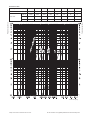 8
8
-
 9
9
-
 10
10
-
 11
11
-
 12
12


in anderen Sprachen
- English: Oventrop 1091062 Owner's manual
- français: Oventrop 1091062 Le manuel du propriétaire
Verwandte Papiere
-
Oventrop 1019497 Bedienungsanleitung
-
-
-
-
-
-
-
Oventrop 1404682 Bedienungsanleitung
-
-
Oventrop 1146064 Bedienungsanleitung
Sonstige Unterlagen
-
Geberit 70373 Installationsanleitung
-
Geberit AquaClean Benutzerhandbuch
-
Geberit ESG Benutzerhandbuch
-
Uponor Combi Port B1000/S1000 Installationsanleitung
-
Truma Combi 6 Operating Instructions Manual
-
 Norma NORMACONNECT PLAST GRIP Fitting Instructions Manual
-
HARVIA CP-RMC-75 Instructions For Installation And Use Manual
-
Baxi Luna Platinum Series Supplementary Manual For The Installer
-
