Uponor Combi Port B1000/S1000 Installationsanleitung
- Typ
- Installationsanleitung

Uponor Combi Port
B 1000/S 1000
EN Installation manual

2 l Uponor Combi Port B 1000/S 1000 l Installation manual
EN
Table of Contents
General information ......................................................................... 3
Validity of the instructions ................................................................... 4
ID plate (example) .............................................................................. 4
Related documents and regulations ................................................... 4
Document retention ............................................................................ 4
Correct operation ................................................................................ 4
Personnel and qualications............................................................... 4
Specialised installers .......................................................................... 5
Installation, commissioning and maintenance .................................... 5
Basic safety information ..................................................................... 5
Danger from electric shock ................................................................. 5
Avoid the risk of burning and scalding ................................................ 5
Avoid frost damage ............................................................................. 5
Information displayed on the device ................................................... 5
Technical data..................................................................................... 5
Device and functional description .................................................. 6
Function description .......................................................................... 6
Components and device connections ................................................ 6
On-wall mounting ............................................................................. 7
On-wall mounting rail .......................................................................... 7
Installing the heat interface unit .......................................................... 7
Installing the on-wall covering ............................................................ 8
Start-up ............................................................................................... 8
In-wall mounting ............................................................................... 9
Preparation of an in-wall-mounted box for installation........................ 9
Installation of an in-wall mounted box ................................................ 9
Mounting the connection rail............................................................... 9
Installing the heat interface unit .......................................................... 9
Connect the connection rail and heat interface unit ......................... 10
Installing the frame and door ............................................................ 10
Start-up ............................................................................................. 10
Recess dimensions ...........................................................................11
Dimensional drawing, base plate, narrow version .............................11
Dimensional drawing, base plate, wide version.................................11
Start-up ............................................................................................ 12
Connecting the hydraulic system ..................................................... 12
Hydraulic schemes, narrow/wide version .................................... 13
Basic equipment for narrow and wide version ................................. 13
Equipment for narrow and wide version (cover page) ..................... 13
Dimensional drawings for narrow version ................................... 14
Dimensional drawings for wide version ....................................... 15
Installed parts ................................................................................. 16
Testing the device prior to commissioning ........................................ 16
Fill/ush ............................................................................................ 16
Venting.............................................................................................. 16
8
Cold water apartment outlet ...................................................... 17
15
Differential pressure regulator (DRG) in the station input .......... 17
12
Thermostatic lead module ......................................................... 17
13
Thermostatic hot water temperature limiter ....................................17
14
Return temperature limiter (RTB) ............................................... 17
Injection circuit (FPI/EPI) .................................................................. 18
10
AQ dynamic zone valve ............................................................. 19
10
AQ static zone valve .................................................................. 20
Actuator on the zone valve ............................................................... 20
Electrics – Cabling ......................................................................... 21
Connection example, constant value control .................................... 21
Troubleshooting ............................................................................. 22
Important information about these instructions................................. 24
Function and energy savings............................................................ 24
Closing off the heat interface unit ..................................................... 25
2 l Uponor Combi Port B 1000/S 1000 l Installation manual

Uponor Combi Port B 1000/S 1000 l Installation manual l 3
EN
General information
Dear Customer,
Before installing the system, the installer must read, understand and
comply with these installation and operating instructions. We reserve
the right to make technical changes. Please keep these instructions
for future use!
1 This unit and its accessories may only be installed by qualied
specialist personnel.
2 The heating system must be planned and implemented in
accordance with generally accepted engineering practices, as
well as the DIN standards and VDI guidelines described below.
If necessary, please observe the applicable and comparable
country-specic regulations and standards. (The list is not
necessarily complete.)
DIN 18380 German construction contract procedures (VOB)
- Part C
DIN 4109 Sound insulation in buildings
DIN EN 6946 Building components and building elements -
Thermal resistance and thermal transmittance
- Calculation method
DIN EN 12831 Heating systems in buildings - Method for
calculation of the design heat load
DIN EN 128282 Heating systems in buildings - Planning of
water-based heating systems
DIN EN 14868 Protection of metallic materials against corrosion
DIN EN 14336 Installation and commissioning of water based
heating systems
VDI 2035 Prevention of damage in water heating
installations
VDI 4704 Water heating installations - Water quality,
pressure maintenance, deaeration - Trainings
VDI/DVGW 6023 Hygiene in drinking-water installations
DIN EN 1717 with national supplements
DIN 1988-100 Codes of practice for drinking
water installations
TRGI Technical Rules for Gas Installation
EneV Energy Saving Directive
Please note that, according to EneV, the heating load of the building
must be recalculated in the event of a major renovation of the
heating system (boiler replacement). The system must be provided
with equipment to enable automatic control according to time and
temperature.
A water analysis is recommended for every drinking water delivery
installation. In the case of warranty claims, water analysis is mandatory.
3 The necessary electrical connections, installation, commissioning
and maintenance work may only be carried out by qualied
specialist personnel. IEC 364 and/or CENELEC HD 384 or DIN
VDE 0100, DIN VDE 0190 and IEC Report 446 or DIN VDE 0110
and EN 50178, EN 60204, EN 60335/Part 1 and Part 51 and/or
local or national provisions must be satised.
Hazard warning: Before performing any work on the controller
or the components connected to it, disconnect the controller
from the power supply as instructed. The outlets are also in
an inactive state under mains voltage.
We would also ask you to install the systems supplied by us
according to the installation instructions. Our warranty shall be
rendered void in the event of damage caused to the systems or to
the heating system or building due to violation of these instructions.
Refurbishments or alterations are only permitted after consultation
with the manufacturer. The manufacturer accepts no liability for
any damage resulting from improper use of the units.
4 This product comes in contact with our most precious foodstuff,
drinking water. We therefore wish to point out some important
installation and operating conditions.
The drinking water installation must be planned and implemented in
accordance with the German Infection Protection Act, in particular
Article 37 of the Drinking Water Ordinance, DIN 1988, DIN 50930
Part 6, DIN 2000, DIN 2001 and DIN 18381 as well as VDI 6003
and VDI/DVGW 6023 and the DVGW Worksheets quoted below,
as well as generally accepted engineering practices. (The list is
not necessarily complete.)
These are:
W 551 Drinking water heating and drinking water piping
systems - Technical measures to reduce Legionella
growth
W 553 Dimensioning of circulation-systems in central drinking
water heating systems
W 291 Cleaning and disinfection of water distribution systems
DVGW W 557 Cleaning and disinfection of drinking water installations
Regulations of local water supply companies The applicable and
comparable country-specic regulations and standards.
There are a few specic points that we would like to point out,
but note that they are not necessarily complete.
• This system may only be installed by qualied specialist
personnel.
• During installation, make sure that the open ends of the pipes
are protected against dirt during work breaks.
• The safety equipment of the drinking water delivery installation
must comply with DIN EN 806-2 and DIN 1988-200 or the
comparable national regulations or standards.
• The system must be ushed and disinfected before
being commissioned and handed over to the user.
• Hot drinking water pipes must be provided with the prescribed
thermal insulation in accordance with EneV and DIN 1988-200.
• The drinking water pipes must be insulated in accordance
with recognised engineering practices.
• The cold water pipes should not be insulated together with
the heating pipes. Thermal separation or, preferably, spatial
separation is required.
Uponor Combi Port B 1000/S 1000 l Installation manual l 3

4 l Uponor Combi Port B 1000/S 1000 l Installation manual
EN
In the case of installations in the public sector (multi family homes,
hotels, retirement homes, hospitals, sports halls, etc.) care must be
taken to ensure that the heated drinking water temperature does not
fall below 60°C and the circulating water re-entering the unit reaches
a minimum temperature of 55°C. This requires accurate calculation
and precise adjustment of the circulating line.
The system is maintained in compliance with DIN EN 806-5 or, outside
Germany, in accordance with national regulations or standards.
Use-related wear of wearing parts, such as pumps, built-in valves
(moving parts, PM valves, etc.) are not considered as defects.
We recommend a maintenance cycle especially for example for the
built-in heat exchanger (test, dirt, sludge, lime), PM valve (functional
test), dirt lter, shut-off valves (functional test), valves such as a
thermostatic lead module, thermostatic hot water temperature limiter,
zone valves, injection valve, differential pressure regulator, pump,
volume measuring unit, thermal premixer or other parts.
5 Please instruct the system users properly and provide them with
these installation and operating instructions together with the
inventory documents.
Please check that the units are complete. Any screws that
are loosened during transport should be retightened.
In the event of leaks that occur during the pressure test, be
sure to depressurise the unit before replacing any affected
components.
Never remove individual parts of the unit (or any other built-in
components) while the system is still under pressure (risk of injury).
If you have any questions about correct operation or function,
please contact your supplier. Of course you are also welcome
to contact us directly anytime.
Validity of the instructions
These installation and operating instructions apply exclusively to
the manufacturer's unit. The type can be found on the ID plate.
The ID plate is located on the base plate of the unit. The ID plate
contains the following information.
• Sales
• Created by
• Device type
• Technical data
• Year built
• Serial number
• Order number
• Production location
ID plate (example)
Device type: Combi Port B 1000
Hz-VI temperature: max. 90°C
TWW ow rate: Exchanger type 1; 12 l/min
Pressure level Hz/TWW: PN 10/PN 6
Year built: 2015
Serial number: D-10-0026036
Order number: 102628
Made in Germany
Related documents and regulations
• Additional documents are valid in conjunction with
these installation and operating instructions.
• When carrying out service work on the unit, it is essential to
observe all instructions for supplementary components and
components of the heating system.
• In all service work pay attention to:
- the recognised technical rules for safe and
professional operations
- the statutory regulations for accident prevention
- the statutory environmental protection regulations
- the stipulations of employer's liability insurance associations
- the relevant safety conditions of the DIN, EN, DVGW, DWGW,
VDE and AGFW standards
- the relevant national and EU regulations for other countries
- and the relevant specications for the recognised rules
of engineering
Document retention
• You should keep these instructions and all other applicable
documents in a safe place, so that they are always available.
• Make sure to hand over all the documents to the operator.
Correct operation
The heat interface unit is intended exclusively for drinking water
heating, control of the downstream domestic heating system and
the measurement of heating energy and cold water consumption
for an apartment or similar unit.
Any other or further use is considered improper use. The
manufacturer/supplier is not liable for resulting damages. The risk
is borne solely by the user. Intended use also includes observance
of all relevant documents and compliance with the inspection and
maintenance conditions.
Under no circumstances should you deviate from the values given
in the technical data.
Personnel and qualifications
The heat interface unit may be operated by the operator or by
personnel authorised by the operator. Service work (assembly,
commissioning and maintenance) on the heat interface unit
requires specialist knowledge. In general, only authorised specialist
tradesmen are allowed to carry out service work on the heat
interface unit.

Uponor Combi Port B 1000/S 1000 l Installation manual l 5
EN
Operator
The operator is responsible for the correct operation of the heating
system.
The operator must:
• have read and understood the operating instructions,
• have reached a statutory minimum age,
• ensure that the heating system is regularly maintained by
an installer.
Specialised installers
The installer is authorised to carry out installation, commissioning
and maintenance work (service and repair).
Authorised installers must have a recognised qualication or
knowledge of the relevant area of expertise and are responsible
for compliance with existing regulations, rules and guidelines.
Work on electrical equipment belonging to the system may only be
carried out by a qualied electrician in accordance with the electrical
engineering regulations. Only personnel with special knowledge and
experience in hydraulics may work on hydraulic equipment.
Installation, commissioning and maintenance
For your own safety, please note that the installation, commissioning
and maintenance of the heat interface unit must be carried out by
sufciently qualied personnel.
Basic safety information
Observe the following instructions for your own safety and the safety
of your environment.
Danger from electric shock
Controllers and pumps are under mains voltage. Contact with
live parts can be fatal or cause serious injury.
• Switch off the power supply immediately when working on
electrical components.
• Work on the electrical system may only be carried out by
qualied electricians.
• Never touch electrical components with wet or damp body parts.
• Never pull on electrical cables.
Avoid the risk of burning and scalding
The surfaces of individual components and the water at the tap
can become very hot.
• Avoid contact with hot surfaces.
• Carefully check the water temperature with a gauge
before touching it
Leaks
If leaks occur, you must follow the instructions below.
• Close all shut-off valves immediately.
• Repair the lick in the appropriate manner.
Avoid frost damage
Without hot water and power supplies, the heat interface unit
is not protected against frost.
• Take the appropriate steps to ensure supply and notify the
operator that the heat interface unit is in operation during
a period of frost (even when the operator is away).
• Take the appropriate steps to ensure supply and notify the
operator that a sufcient temperature must be maintained
at the installation site of the heat interface unit and in the
accommodation.
• Avoiding property damage due to improper maintenance
• Perform yearly maintenance on the station.
Information displayed on the device
• Observe the instructions displayed directly on the device.
• Maintain such displayed instructions in a fully legible state.
Material damage due to incorrect additional components, avoidance
of spare and wearing parts, use of unauthorised components, spare
parts and wear parts that have not been tested with the system can
damage the heat interface unit.
The installation of non-approved components, spare parts and
wear parts, as well as unauthorised modications and alterations
are considered to be improper and may restrict the function, safety
and warranty. We accept no liability in such cases.
• Use only original parts from the manufacturer or spare parts
approved by the manufacturer for replacement purposes.
Recommendations, optimum values for water
dH <dH 0.11
pH value >8.2 - >8.5 Heating water
Technical data
Materials
Fittings Brass/dezincing resistant brass
Pipes Stainless steel 1.4401
Heat exchanger Stainless steel 1.4404/copper solder
and diffusion
General information
Max. operating
temperature
90°C
Operating pressure PN10
Min. cold water pressure approx. 2 bar
Max. cold water pressure approx. 4 bar
Connections 3/4“ or 1“ IG, at-sealing

6 l Uponor Combi Port B 1000/S 1000 l Installation manual
EN
Device and functional description
Function description
The heat interface unit supplies a residential unit with hot water and
heating. The drinking water is heated as required by means of a
stainless steel plate heat exchanger using the through ow principle
1
. The great thermal length of the heat exchanger ensures very
good cooling of the heating water and low return temperatures.
The energy is supplied by heating water with a ow temperature
of at least 55°C via the hot water supply line.
The drinking water temperature is controlled by a pressure-controlled
proportional-quantity controller (PM valve
2
). The PM valve only
opens when hot water is dispensed. Upon completion of dispensing,
the valve stops the heating of the exchanger.
If constant ow temperatures are assumed, the same dispensing
temperature is always achieved with the proportional ow control
for small and large dispensing volumes.
Thanks to the thermostatic hot water temperature limiter
13
, a
stable dispensing temperature can be achieved even with fluctuating
flow temperatures (optional).
A thermostatic lead module
12
(optional) is used on the last unit on a
line or at greater distances from the main line and prevents the risers
from cooling down when not dispensing.
The unit can be balanced with the regulating
10
valve for the
heating side. A 2-point actuator can be mounted on the valve,
which is controlled by a room thermostat (optional).
The differential pressure controller
15
(optional) in the heat
interface unit ensures correct hydraulic autobalancing. If this
controller is not installed in the station, it must be incorporated
in the pipeline.
1 Plate heat exchangers
2 Proportional volume control (PV control)
3 Coldwater orice plate (in screw connection)
4 Sensor pocket WMZ M10x1, submersible
6 Ventilation
7 WMZ adaptor
9 Dirt collector
10 Zone valve for limiting heating ow -for apartments
B TWW in apartments
C TW from pipeline
D HZ-VL-PR
E HZ-RL-PR
F HZ-VL-SEK
G HZ-RL-SEK
I HZ-VL add-on HK
J HZ-RL add-on HK
Additional components with extended equipment
5 Draining
8 Coldwater meter adaptor
12 Thermostatic lead module
13 Thermostatic hot water temperature limiter
15 Differential pressure regulator primarily in the station input
17 Isolating ball valve
19 Pump
21 Check valve
22 Control valve for bypass section
23 Thermostatic FBH regulation 20-50° C
A TW in apartments
Components and device connections
Basic equipment for narrow and wide version
Note: The illustration shows a sample set-up.
Individual modules may vary in appearance.
The legend-based numbering is not continuous.
A
B C D E F G JI
7
1
17
9
4
19
12
23
13
10
21
22
15
6
5
8
9
6
6
2
3

Uponor Combi Port B 1000/S 1000 l Installation manual l 7
EN
On-wall mounting
On-wall mounting rail
1 Mark the hole positions on the wall.
Note: see also the dimensional drawings on page 11.
Pay attention to horizontal alignment!
2 Drill holes.
3 Screw the on-wall mounting rail to the wall using the
mounting material provided.
The connection rail is xed to the wall and the piping to the on-wall
mounting rail can be installed.
Installing the heat interface unit
Connecting the on-wall mounted rail and heat interface unit
1 Mark the hole positions on the wall.
Pay attention to horizontal alignment.
2 Drill holes.
3 Screw the heat interface unit to the wall using the
mounting material provided.
4 The 3/4“ screw connection of the heat interface unit must be
joined to screw connections of the on-wall mounting rail (3/4"
AG).
The at seals provided must be inserted before joining.
The screw connections are to be tightened with lock nuts.
(detail A)
Please note:
The seal of the screw connections should be checked!
A
1.
2.
Bohrlöcher bohren.
Markierung für Bohrungen an der Wand vornehmen.
(Auf waagerechte Ausrichtung achten!)
Schritt 1: Montage Aufputzschiene
B
C
A
D
E
3.
Aufputzschiene mit
beiliegendem
Befestigungsmaterial an
der Wand verschrauben.
Die Anschlussschiene ist an der Wand befestigt und die
Installation der Rohrleitungen zur AP-Schiene kann
vorgenommen werden.
Bohrlöcher bohren.
2.
G
F
E
D
(A) Mauerwerk
(B) Bohrung
(C) Dübel
(D) AP-Schiene
(E) Sechskant-
schraube
(F) Wohnungsstation
(G) Dichtung
(H) AP-Verkleidung
1.
Markierungen für Bohrungen an der Wand vornehmen (siehe
Maßzeichnung) Auf waagerechte Ausrichtung achten!
A
C
B
Detail A
F
D
G
A
F
D
1.
Die Verkleidung ist auf die Aufhängung der Grundblechs der
Wohnungsstation aufzusetzen.
H
Hinweis:
Die dargestellte Abbildung ist eine
prinzipdarstellung ohne Anspruch auf
Vollständigkeit. Alle Angaben ohne Gewähr.
Achtung:
Fachgerechte Befestigung
nach Beschaffenheit der Wände und
Träger ausführen!
Schritt 2: Montage Wohnungsstation
Schritt 3: Verbinden von Aufputzschiene und
Wohnungsstation
Beachten Sie bei Inbetriebnahme nachfolgenden
Spülhinweis:
Vor dem Befüllen des Gerätes müssen Sie vorab die gesamte
Heizungsanlage und die Wohnungsheizung gründlich spülen.
Vor der Inbetriebnahme müssen Sie die Schmutzfänger
kontrollieren und ggf. spülen/reinigen. Kontrollieren Sie die
Dichtigkeit der flach dichtenden
Verbindungen.
Kontern Sie beim Nachziehen von Verbindungen immer die
Gegenseite. Entlüften Sie die aufgestaute Luft in der
Wohnungsstation durch Öffnen der Entlüftungen. Beachten
Sie dabei den Anlagenbetriebsdruck und füllen Sie ggf. nach.
Schritt 4: Montage der Aufputzverkleidung
Montageanleitung
Aufputz-Wandmontage
Schritt 5: Inbetriebnahme
4.
Beachten Sie: Dichtigkeit der Verschraubungen
sind zu prüfen!
Beiliegende Flachdichtungen sind vor dem
Verbinden einzulegen. Die Verschraubungen sind
durch kontern festzuziehen. (Detail A)
Die 3/4"-Verschraubung der Wohnungsstation
(3/4"ÜWM) sind mit den Verschraubungen der
Aufputzschiene (3/4"AG) zu verschrauben.
3.
Wohnungsstation mit
beiliegendem
Besfestigungsmaterial an
der Wand verschrauben.
F
8
E
D
C
B
A
G
H
J
K
L
M
7
6
5
4
3
2
1
9
10
11
12
13
14
15
16
9
1
2
3
4
5
6
7
8
10
11
12
K
G
A
B
C
D
E
F
H
J
M
14
15
16
von
Bl.
FLW
Die Weitergabe sowie Vervielfältigung, Verwertung und Mitteilung dieses Inhalts ist nur mit unserer
ausdrücklichen Genehmigung gestattet. Zuwiderhandlungen verpflichten zu Schadenersatz.
Alle Rechte für den Fall der Patenterteilung oder Gebrauchsmustereintragung vorbehalten.
Delta Systemtechnik GmbH
Heineckes Feld 9 - 29227 Celle
Deutschland - Germany
PAT
Für Irrtümer und Druckfehler keine Haftung.
Technische Änderungen vorbehalten.
Änderung
Index
Schutzvermerk ISO 16016 beachten.
Maßstab
Freigabe
Datum
Geprüft
Gezeich.
21.08.2017
Name
21.08.2017
Art.-Nr.
Gezeichnet/Datum
Freigabe/Datum
Geprüft/Datum
Werkstoff
Gewicht(kg)
Benennung
Status
Blatt
A1
1
Blatt2
Montageanleitung
Freigegeben
1:10
Aufputz-Wandmontage
Delta Systemtechnik
A
1.
2.
Bohrlöcher bohren.
Markierung für Bohrungen an der Wand vornehmen.
(Auf waagerechte Ausrichtung achten!)
Schritt 1: Montage Aufputzschiene
B
C
A
D
E
3.
Aufputzschiene mit
beiliegendem
Befestigungsmaterial an
der Wand verschrauben.
Die Anschlussschiene ist an der Wand befestigt und die
Installation der Rohrleitungen zur AP-Schiene kann
vorgenommen werden.
Bohrlöcher bohren.
2.
G
F
E
D
(A) Mauerwerk
(B) Bohrung
(C) Dübel
(D) AP-Schiene
(E) Sechskant-
schraube
(F) Wohnungsstation
(G) Dichtung
(H) AP-Verkleidung
1.
Markierungen für Bohrungen an der Wand vornehmen (siehe
Maßzeichnung) Auf waagerechte Ausrichtung achten!
A
C
B
Detail A
F
D
G
A
F
D
1.
Die Verkleidung ist auf die Aufhängung der Grundblechs der
Wohnungsstation aufzusetzen.
H
Hinweis:
Die dargestellte Abbildung ist eine
prinzipdarstellung ohne Anspruch auf
Vollständigkeit. Alle Angaben ohne Gewähr.
Achtung:
Fachgerechte Befestigung
nach Beschaffenheit der Wände und
Träger ausführen!
Schritt 2: Montage Wohnungsstation
Schritt 3: Verbinden von Aufputzschiene und
Wohnungsstation
Beachten Sie bei Inbetriebnahme nachfolgenden
Spülhinweis:
Vor dem Befüllen des Gerätes müssen Sie vorab die gesamte
Heizungsanlage und die Wohnungsheizung gründlich spülen.
Vor der Inbetriebnahme müssen Sie die Schmutzfänger
kontrollieren und ggf. spülen/reinigen. Kontrollieren Sie die
Dichtigkeit der flach dichtenden
Verbindungen.
Kontern Sie beim Nachziehen von Verbindungen immer die
Gegenseite. Entlüften Sie die aufgestaute Luft in der
Wohnungsstation durch Öffnen der Entlüftungen. Beachten
Sie dabei den Anlagenbetriebsdruck und füllen Sie ggf. nach.
Schritt 4: Montage der Aufputzverkleidung
Montageanleitung
Aufputz-Wandmontage
Schritt 5: Inbetriebnahme
4.
Beachten Sie: Dichtigkeit der Verschraubungen
sind zu prüfen!
Beiliegende Flachdichtungen sind vor dem
Verbinden einzulegen. Die Verschraubungen sind
durch kontern festzuziehen. (Detail A)
Die 3/4"-Verschraubung der Wohnungsstation
(3/4"ÜWM) sind mit den Verschraubungen der
Aufputzschiene (3/4"AG) zu verschrauben.
3.
Wohnungsstation mit
beiliegendem
Besfestigungsmaterial an
der Wand verschrauben.
F
8
E
D
C
B
A
G
H
J
K
L
M
7
6
5
4
3
2
1
9
10
11
12
13
14
15
16
9
1
2
3
4
5
6
7
8
10
11
12
K
G
A
B
C
D
E
F
H
J
M
14
15
16
von
Bl.
FLW
Die Weitergabe sowie Vervielfältigung, Verwertung und Mitteilung dieses Inhalts ist nur mit unserer
ausdrücklichen Genehmigung gestattet. Zuwiderhandlungen verpflichten zu Schadenersatz.
Alle Rechte für den Fall der Patenterteilung oder Gebrauchsmustereintragung vorbehalten.
Delta Systemtechnik GmbH
Heineckes Feld 9 - 29227 Celle
Deutschland - Germany
PAT
Für Irrtümer und Druckfehler keine Haftung.
Technische Änderungen vorbehalten.
Änderung
Index
Schutzvermerk ISO 16016 beachten.
Maßstab
Freigabe
Datum
Geprüft
Gezeich.
21.08.2017
Name
21.08.2017
Art.-Nr.
Gezeichnet/Datum
Freigabe/Datum
Geprüft/Datum
Werkstoff
Gewicht(kg)
Benennung
Status
Blatt
A1
1
Blatt2
Montageanleitung
Freigegeben
1:10
Aufputz-Wandmontage
Delta Systemtechnik
A Masonry E Hexagonal bolt
B Hole F Heat interface unit
C Anchor G Seal
D AP rail H AP covering
A
1.
2.
Bohrlöcher bohren.
Markierung für Bohrungen an der Wand vornehmen.
(Auf waagerechte Ausrichtung achten!)
Schritt 1: Montage Aufputzschiene
B
C
A
D
E
3.
Aufputzschiene mit
beiliegendem
Befestigungsmaterial an
der Wand verschrauben.
Die Anschlussschiene ist an der Wand befestigt und die
Installation der Rohrleitungen zur AP-Schiene kann
vorgenommen werden.
Bohrlöcher bohren.
2.
G
F
E
D
(A) Mauerwerk
(B) Bohrung
(C) Dübel
(D) AP-Schiene
(E) Sechskant-
schraube
(F) Wohnungsstation
(G) Dichtung
(H) AP-Verkleidung
1.
Markierungen für Bohrungen an der Wand vornehmen (siehe
Maßzeichnung) Auf waagerechte Ausrichtung achten!
A
C
B
Detail A
F
D
G
A
F
D
1.
Die Verkleidung ist auf die Aufhängung der Grundblechs der
Wohnungsstation aufzusetzen.
H
Hinweis:
Die dargestellte Abbildung ist eine
prinzipdarstellung ohne Anspruch auf
Vollständigkeit. Alle Angaben ohne Gewähr.
Achtung:
Fachgerechte Befestigung
nach Beschaffenheit der Wände und
Träger ausführen!
Schritt 2: Montage Wohnungsstation
Schritt 3: Verbinden von Aufputzschiene und
Wohnungsstation
Beachten Sie bei Inbetriebnahme nachfolgenden
Spülhinweis:
Vor dem Befüllen des Gerätes müssen Sie vorab die gesamte
Heizungsanlage und die Wohnungsheizung gründlich spülen.
Vor der Inbetriebnahme müssen Sie die Schmutzfänger
kontrollieren und ggf. spülen/reinigen. Kontrollieren Sie die
Dichtigkeit der flach dichtenden
Verbindungen.
Kontern Sie beim Nachziehen von Verbindungen immer die
Gegenseite. Entlüften Sie die aufgestaute Luft in der
Wohnungsstation durch Öffnen der Entlüftungen. Beachten
Sie dabei den Anlagenbetriebsdruck und füllen Sie ggf. nach.
Schritt 4: Montage der Aufputzverkleidung
Montageanleitung
Aufputz-Wandmontage
Schritt 5: Inbetriebnahme
4.
Beachten Sie: Dichtigkeit der Verschraubungen
sind zu prüfen!
Beiliegende Flachdichtungen sind vor dem
Verbinden einzulegen. Die Verschraubungen sind
durch kontern festzuziehen. (Detail A)
Die 3/4"-Verschraubung der Wohnungsstation
(3/4"ÜWM) sind mit den Verschraubungen der
Aufputzschiene (3/4"AG) zu verschrauben.
3.
Wohnungsstation mit
beiliegendem
Besfestigungsmaterial an
der Wand verschrauben.
F
8
E
D
C
B
A
G
H
J
K
L
M
7
6
5
4
3
2
1
9
10
11
12
13
14
15
16
9
1
2
3
4
5
6
7
8
10
11
12
K
G
A
B
C
D
E
F
H
J
M
14
15
16
von
Bl.
FLW
Die Weitergabe sowie Vervielfältigung, Verwertung und Mitteilung dieses Inhalts ist nur mit unserer
ausdrücklichen Genehmigung gestattet. Zuwiderhandlungen verpflichten zu Schadenersatz.
Alle Rechte für den Fall der Patenterteilung oder Gebrauchsmustereintragung vorbehalten.
Delta Systemtechnik GmbH
Heineckes Feld 9 - 29227 Celle
Deutschland - Germany
PAT
Für Irrtümer und Druckfehler keine Haftung.
Technische Änderungen vorbehalten.
Änderung
Index
Schutzvermerk ISO 16016 beachten.
Maßstab
Freigabe
Datum
Geprüft
Gezeich.
21.08.2017
Name
21.08.2017
Art.-Nr.
Gezeichnet/Datum
Freigabe/Datum
Geprüft/Datum
Werkstoff
Gewicht(kg)
Benennung
Status
Blatt
A1
1
Blatt2
Montageanleitung
Freigegeben
1:10
Aufputz-Wandmontage
Delta Systemtechnik

8 l Uponor Combi Port B 1000/S 1000 l Installation manual
EN
Installing the on-wall covering
1 The covering is to be placed on the mounting of the base plate
of the heat interface unit.
Start-up
Observe the following ushing instructions during
commissioning:
1 Before lling the device, you must rst thoroughly ush the
entire heating system and the apartment heating system.
Before commissioning, you must check the dirt collectors
and, if necessary, ush/clean them.
2 Check the tightness of the at-seal connections.
3 When tightening connections, always lock the opposite side.
Vent the accumulated air in the heat interface unit by opening
the vents. Observe the system operating pressure and top up
if necessary.
Caution:
Mount according to the condition of the walls and supports!
Note:
The illustration shown is a schematic representation without
any claim to completeness. All data provided without warranty.
A
1.
2.
Bohrlöcher bohren.
Markierung für Bohrungen an der Wand vornehmen.
(Auf waagerechte Ausrichtung achten!)
Schritt 1: Montage Aufputzschiene
B
C
A
D
E
3.
Aufputzschiene mit
beiliegendem
Befestigungsmaterial an
der Wand verschrauben.
Die Anschlussschiene ist an der Wand befestigt und die
Installation der Rohrleitungen zur AP-Schiene kann
vorgenommen werden.
Bohrlöcher bohren.
2.
G
F
E
D
(A) Mauerwerk
(B) Bohrung
(C) Dübel
(D) AP-Schiene
(E) Sechskant-
schraube
(F) Wohnungsstation
(G) Dichtung
(H) AP-Verkleidung
1.
Markierungen für Bohrungen an der Wand vornehmen (siehe
Maßzeichnung) Auf waagerechte Ausrichtung achten!
A
C
B
Detail A
F
D
G
A
F
D
1.
Die Verkleidung ist auf die Aufhängung der Grundblechs der
Wohnungsstation aufzusetzen.
H
Hinweis:
Die dargestellte Abbildung ist eine
prinzipdarstellung ohne Anspruch auf
Vollständigkeit. Alle Angaben ohne Gewähr.
Achtung:
Fachgerechte Befestigung
nach Beschaffenheit der Wände und
Träger ausführen!
Schritt 2: Montage Wohnungsstation
Schritt 3: Verbinden von Aufputzschiene und
Wohnungsstation
Beachten Sie bei Inbetriebnahme nachfolgenden
Spülhinweis:
Vor dem Befüllen des Gerätes müssen Sie vorab die gesamte
Heizungsanlage und die Wohnungsheizung gründlich spülen.
Vor der Inbetriebnahme müssen Sie die Schmutzfänger
kontrollieren und ggf. spülen/reinigen. Kontrollieren Sie die
Dichtigkeit der flach dichtenden
Verbindungen.
Kontern Sie beim Nachziehen von Verbindungen immer die
Gegenseite. Entlüften Sie die aufgestaute Luft in der
Wohnungsstation durch Öffnen der Entlüftungen. Beachten
Sie dabei den Anlagenbetriebsdruck und füllen Sie ggf. nach.
Schritt 4: Montage der Aufputzverkleidung
Montageanleitung
Aufputz-Wandmontage
Schritt 5: Inbetriebnahme
4.
Beachten Sie: Dichtigkeit der Verschraubungen
sind zu prüfen!
Beiliegende Flachdichtungen sind vor dem
Verbinden einzulegen. Die Verschraubungen sind
durch kontern festzuziehen. (Detail A)
Die 3/4"-Verschraubung der Wohnungsstation
(3/4"ÜWM) sind mit den Verschraubungen der
Aufputzschiene (3/4"AG) zu verschrauben.
3.
Wohnungsstation mit
beiliegendem
Besfestigungsmaterial an
der Wand verschrauben.
F
8
E
D
C
B
A
G
H
J
K
L
M
7
6
5
4
3
2
1
9
10
11
12
13
14
15
16
9
1
2
3
4
5
6
7
8
10
11
12
K
G
A
B
C
D
E
F
H
J
M
14
15
16
von
Bl.
FLW
Die Weitergabe sowie Vervielfältigung, Verwertung und Mitteilung dieses Inhalts ist nur mit unserer
ausdrücklichen Genehmigung gestattet. Zuwiderhandlungen verpflichten zu Schadenersatz.
Alle Rechte für den Fall der Patenterteilung oder Gebrauchsmustereintragung vorbehalten.
Delta Systemtechnik GmbH
Heineckes Feld 9 - 29227 Celle
Deutschland - Germany
PAT
Für Irrtümer und Druckfehler keine Haftung.
Technische Änderungen vorbehalten.
Änderung
Index
Schutzvermerk ISO 16016 beachten.
Maßstab
Freigabe
Datum
Geprüft
Gezeich.
21.08.2017
Name
21.08.2017
Art.-Nr.
Gezeichnet/Datum
Freigabe/Datum
Geprüft/Datum
Werkstoff
Gewicht(kg)
Benennung
Status
Blatt
A1
1
Blatt2
Montageanleitung
Freigegeben
1:10
Aufputz-Wandmontage
Delta Systemtechnik
A
1.
2.
Bohrlöcher bohren.
Markierung für Bohrungen an der Wand vornehmen.
(Auf waagerechte Ausrichtung achten!)
Schritt 1: Montage Aufputzschiene
B
C
A
D
E
3.
Aufputzschiene mit
beiliegendem
Befestigungsmaterial an
der Wand verschrauben.
Die Anschlussschiene ist an der Wand befestigt und die
Installation der Rohrleitungen zur AP-Schiene kann
vorgenommen werden.
Bohrlöcher bohren.
2.
G
F
E
D
(A) Mauerwerk
(B) Bohrung
(C) Dübel
(D) AP-Schiene
(E) Sechskant-
schraube
(F) Wohnungsstation
(G) Dichtung
(H) AP-Verkleidung
1.
Markierungen für Bohrungen an der Wand vornehmen (siehe
Maßzeichnung) Auf waagerechte Ausrichtung achten!
A
C
B
Detail A
F
D
G
A
F
D
1.
Die Verkleidung ist auf die Aufhängung der Grundblechs der
Wohnungsstation aufzusetzen.
H
Hinweis:
Die dargestellte Abbildung ist eine
prinzipdarstellung ohne Anspruch auf
Vollständigkeit. Alle Angaben ohne Gewähr.
Achtung:
Fachgerechte Befestigung
nach Beschaffenheit der Wände und
Träger ausführen!
Schritt 2: Montage Wohnungsstation
Schritt 3: Verbinden von Aufputzschiene und
Wohnungsstation
Beachten Sie bei Inbetriebnahme nachfolgenden
Spülhinweis:
Vor dem Befüllen des Gerätes müssen Sie vorab die gesamte
Heizungsanlage und die Wohnungsheizung gründlich spülen.
Vor der Inbetriebnahme müssen Sie die Schmutzfänger
kontrollieren und ggf. spülen/reinigen. Kontrollieren Sie die
Dichtigkeit der flach dichtenden
Verbindungen.
Kontern Sie beim Nachziehen von Verbindungen immer die
Gegenseite. Entlüften Sie die aufgestaute Luft in der
Wohnungsstation durch Öffnen der Entlüftungen. Beachten
Sie dabei den Anlagenbetriebsdruck und füllen Sie ggf. nach.
Schritt 4: Montage der Aufputzverkleidung
Montageanleitung
Aufputz-Wandmontage
Schritt 5: Inbetriebnahme
4.
Beachten Sie: Dichtigkeit der Verschraubungen
sind zu prüfen!
Beiliegende Flachdichtungen sind vor dem
Verbinden einzulegen. Die Verschraubungen sind
durch kontern festzuziehen. (Detail A)
Die 3/4"-Verschraubung der Wohnungsstation
(3/4"ÜWM) sind mit den Verschraubungen der
Aufputzschiene (3/4"AG) zu verschrauben.
3.
Wohnungsstation mit
beiliegendem
Besfestigungsmaterial an
der Wand verschrauben.
F
8
E
D
C
B
A
G
H
J
K
L
M
7
6
5
4
3
2
1
9
10
11
12
13
14
15
16
9
1
2
3
4
5
6
7
8
10
11
12
K
G
A
B
C
D
E
F
H
J
M
14
15
16
von
Bl.
FLW
Die Weitergabe sowie Vervielfältigung, Verwertung und Mitteilung dieses Inhalts ist nur mit unserer
ausdrücklichen Genehmigung gestattet. Zuwiderhandlungen verpflichten zu Schadenersatz.
Alle Rechte für den Fall der Patenterteilung oder Gebrauchsmustereintragung vorbehalten.
Delta Systemtechnik GmbH
Heineckes Feld 9 - 29227 Celle
Deutschland - Germany
PAT
Für Irrtümer und Druckfehler keine Haftung.
Technische Änderungen vorbehalten.
Änderung
Index
Schutzvermerk ISO 16016 beachten.
Maßstab
Freigabe
Datum
Geprüft
Gezeich.
21.08.2017
Name
21.08.2017
Art.-Nr.
Gezeichnet/Datum
Freigabe/Datum
Geprüft/Datum
Werkstoff
Gewicht(kg)
Benennung
Status
Blatt
A1
1
Blatt2
Montageanleitung
Freigegeben
1:10
Aufputz-Wandmontage
Delta Systemtechnik
A Masonry I Washer
B Hole J Screed
C Anchor K Door
D AP rail L Frame
E Hexagonal bolt N Screed impact plate
F Heat interface unit M Bolt
G Seals O Cross strut
H Case P Bare oor

Uponor Combi Port B 1000/S 1000 l Installation manual l 9
EN
Preparation of an in-wall-mounted box for
installation
Dismantle the frame and the door by drawing it out of the case.
Keep the parts for later installation.
Installing an in-wall mounted box
1 Mark the hole positions in the wall aperture. Pay attention to
horizontal alignment.
Note: For freestanding installations, set the height according
to the table and adjust the feet accordingly.
In the case of wall-mounted installations in cases, the incised
metre mark must be observed.
2 Drill holes.
3 Screw the prepared case into the wall aperture using
the mounting material provided.
Mounting the connection rail
1 Mount the connecting rail on the bolts provided in the case
(see dimensional drawing) using the mounting material provided.
2 The connection rail is xed in the in-wall mounting case and the
piping for the rail can be installed.
Installing the heat interface unit
1 Mount the heat interface unit on the bolts provided (see
dimensional drawing) and on the case using the mounting
material provided.
Vorbereitung Unterputzkasten für Einbau
H
L
K
O
N
1.
Demontage des Rahmens und der Tür durch
herausziehen aus der Zarge
Aufbehalten der Teile für späteren Einbau
1.
Markierungen für Bohrungen in dem Wandausschnitt vornehmen.
(Auf waagerechte Ausrichtung achten)
Hinweis
: Bei
bodenstehender Montage
Höhenmaß nach Tabelle (Tabelle 1)
festlegen und Standfüße dementsprechend einstellen
Bei
wandhängender Montage
in Zarge eingestanzten Meterstrich
beachten.
2.
Bohrlöcher bohren.
3.
Vorbereitete Zarge mit beiliegendem Befestigungsmaterial in dem Wandausschnitt
verschrauben.
A
H
E
P
Schritt 1: Montage Unterputzkasten
C
B
Montage der Anschlussschiene auf den dafür vorgesehenen Bolzen (siehe
Maßzeichnung) der Zarge mit dem beiliegendem Befestigungsmaterial.
1.
Die Anschlussschiene ist in dem UP-Kasten befestigt und die
Installation der Rohrleitungen zu der Schiene kann vorgenommen
werden.
A
H
D
I
E
P
Schritt 2: Montage Anschlussschiene
M
Schritt 3: Montage der Wohnungsstation
1.
Montage der Wohnungs-station auf den dafür vorgesehenen
Bolzen (siehe Maßzeichnung) der Zarge mit dem beiliegendem
Befestigungsmaterial.
A
H
D
I
E
P
F
1.
Die 3/4"-Verschraubung der Wohnungsstation (3/4"ÜWM) ist
mit den Verschraubungen der Anschlussschiene (3/4"AG) zu
verschrauben.
Beiliegende Flachdichtungen sind vor dem Verbinden
einzulegen. Die Verschraubungen sind durch kontern
festzuziehen. (Detail A)
Beachten Sie: Dichtigkeit der Verschraubungen sind zu
prüfen!
A
F
Schritt 4: Verbinden von Anschlussschiene und Wohnungsstation
Detail A
D
G
F
Schritt 5: Rahmen und Tür montieren
P
J
A
F
D
K
L
N
1. Tür und Rahmen des UP-Kastens montieren.
Estrich kann jetzt verlegt werden.
Beachten Sie bei Inbetriebnahme nachfolgenden Spülhinweis:
Vor dem Befüllen des Gerätes müssen Sie vorab die gesamte Heizungsanlage und
die Wohnungsheizung grundlich spülen. Vor der Inbetriebnahme müssen Sie die
Schmutzfänger kontrollieren und ggf. spülen/reinigen.
Kontrollieren Sie die Dichtigkeit der flach dichtenden Verbindungen.
Kontern Sie beim Nachziehen von Verbindungen immmer die Gegenseite.
Entlüften Sie die aufgestaute Luft in der Wohnungsstation durch Öffnen der
Entlüftungen.
Beachten Sie dabei den Anlagenbetriebsdruck und füllen Sie ggf. nach.
Montageanleitung
Unterputz-Montage
Achtung:
Fachgerechte
Befestigung nach Beschaffenheit
der Wände und Träger ausführen!
Hinweis:
Die dargestellte Abbildung ist eine
Prinzipdarstellung ohne Anspruch auf
Vollständigkeit. Alle Angaben ohne Gewähr!
Schritt 6: Inbetriebnahme
(A) Mauerwerk
(B) Bohrung
(C) Dübel
(D) AP-Schiene
(E) Sechskantschraube
(F) Wohnungsstation
(G) Dichtung
(H) Zarge
(I) Unterlegscheibe
(J) Estrich
(K) Tür
(L) Rahmen
(M) Bolzen
(N) Estrichprallblech
(O) Querstrebe
(P) Rohfußboden
F
8
E
D
C
B
A
G
H
J
K
L
M
7
6
5
4
3
2
1
9
10
11
12
13
14
15
16
9
1
2
3
4
5
6
7
8
10
11
12
K
G
A
B
C
D
E
F
H
J
M
14
15
16
von
Bl.
FLW
Die Weitergabe sowie Vervielfältigung, Verwertung und Mitteilung dieses Inhalts ist nur mit unserer
ausdrücklichen Genehmigung gestattet. Zuwiderhandlungen verpflichten zu Schadenersatz.
Alle Rechte für den Fall der Patenterteilung oder Gebrauchsmustereintragung vorbehalten.
Delta Systemtechnik GmbH
Heineckes Feld 9 - 29227 Celle
Deutschland - Germany
PAT
Für Irrtümer und Druckfehler keine Haftung.
Technische Änderungen vorbehalten.
Änderung
Index
Schutzvermerk ISO 16016 beachten.
Maßstab
Freigabe
Datum
Geprüft
Gezeich.
22.08.2017
Name
22.08.2017
Art.-Nr.
Gezeichnet/Datum
Freigabe/Datum
Geprüft/Datum
Werkstoff
Gewicht(kg)
Benennung
Status
Blatt
A1
1
Blatt2
Montageanleitung
Freigegeben
1:10
Unterputz-Wandmontage
Delta Systemtechnik
In-wall mounting

10 l Uponor Combi Port B 1000/S 1000 l Installation manual
EN
Connecting the connection rail and heat interface
unit
1 The 3/4“ screw connection of the heat interface unit must be
joined to screw connections of the connection rail (3/4" AG).
2 The at seals provided must be inserted before joining. The screw
connections are to be tightened with lock nuts. (detail A)
Please note:
The seal of the screw connections should be checked!
Installing the frame and door
1 Install the door and frame of the in-wall mounting box.
The screed can now be laid.
Start-up
Observe the following ushing instructions during commissioning:
1 Before lling the device, you must rst thoroughly ush the
entire heating system and the apartment heating system.
Before commissioning, you must check the dirt collectors and,
if necessary, ush/clean them.
3 Check the tightness of the at-seal connections.
4 When tightening connections, always lock the opposite side.
5 Vent the accumulated air in the heat interface unit by opening
the vents.
Observe the system operating pressure and top up if necessary.
Vorbereitung Unterputzkasten für Einbau
H
L
K
O
N
1.
Demontage des Rahmens und der Tür durch
herausziehen aus der Zarge
Aufbehalten der Teile für späteren Einbau
1.
Markierungen für Bohrungen in dem Wandausschnitt vornehmen.
(Auf waagerechte Ausrichtung achten)
Hinweis
: Bei
bodenstehender Montage
Höhenmaß nach Tabelle (Tabelle 1)
festlegen und Standfüße dementsprechend einstellen
Bei
wandhängender Montage
in Zarge eingestanzten Meterstrich
beachten.
2.
Bohrlöcher bohren.
3.
Vorbereitete Zarge mit beiliegendem Befestigungsmaterial in dem Wandausschnitt
verschrauben.
A
H
E
P
Schritt 1: Montage Unterputzkasten
C
B
Montage der Anschlussschiene auf den dafür vorgesehenen Bolzen (siehe
Maßzeichnung) der Zarge mit dem beiliegendem Befestigungsmaterial.
1.
Die Anschlussschiene ist in dem UP-Kasten befestigt und die
Installation der Rohrleitungen zu der Schiene kann vorgenommen
werden.
A
H
D
I
E
P
Schritt 2: Montage Anschlussschiene
M
Schritt 3: Montage der Wohnungsstation
1.
Montage der Wohnungs-station auf den dafür vorgesehenen
Bolzen (siehe Maßzeichnung) der Zarge mit dem beiliegendem
Befestigungsmaterial.
A
H
D
I
E
P
F
1.
Die 3/4"-Verschraubung der Wohnungsstation (3/4"ÜWM) ist
mit den Verschraubungen der Anschlussschiene (3/4"AG) zu
verschrauben.
Beiliegende Flachdichtungen sind vor dem Verbinden
einzulegen. Die Verschraubungen sind durch kontern
festzuziehen. (Detail A)
Beachten Sie: Dichtigkeit der Verschraubungen sind zu
prüfen!
A
F
Schritt 4: Verbinden von Anschlussschiene und Wohnungsstation
Detail A
D
G
F
Schritt 5: Rahmen und Tür montieren
P
J
A
F
D
K
L
N
1. Tür und Rahmen des UP-Kastens montieren.
Estrich kann jetzt verlegt werden.
Beachten Sie bei Inbetriebnahme nachfolgenden Spülhinweis:
Vor dem Befüllen des Gerätes müssen Sie vorab die gesamte Heizungsanlage und
die Wohnungsheizung grundlich spülen. Vor der Inbetriebnahme müssen Sie die
Schmutzfänger kontrollieren und ggf. spülen/reinigen.
Kontrollieren Sie die Dichtigkeit der flach dichtenden Verbindungen.
Kontern Sie beim Nachziehen von Verbindungen immmer die Gegenseite.
Entlüften Sie die aufgestaute Luft in der Wohnungsstation durch Öffnen der
Entlüftungen.
Beachten Sie dabei den Anlagenbetriebsdruck und füllen Sie ggf. nach.
Montageanleitung
Unterputz-Montage
Achtung:
Fachgerechte
Befestigung nach Beschaffenheit
der Wände und Träger ausführen!
Hinweis:
Die dargestellte Abbildung ist eine
Prinzipdarstellung ohne Anspruch auf
Vollständigkeit. Alle Angaben ohne Gewähr!
Schritt 6: Inbetriebnahme
(A) Mauerwerk
(B) Bohrung
(C) Dübel
(D) AP-Schiene
(E) Sechskantschraube
(F) Wohnungsstation
(G) Dichtung
(H) Zarge
(I) Unterlegscheibe
(J) Estrich
(K) Tür
(L) Rahmen
(M) Bolzen
(N) Estrichprallblech
(O) Querstrebe
(P) Rohfußboden
F
8
E
D
C
B
A
G
H
J
K
L
M
7
6
5
4
3
2
1
9
10
11
12
13
14
15
16
9
1
2
3
4
5
6
7
8
10
11
12
K
G
A
B
C
D
E
F
H
J
M
14
15
16
von
Bl.
FLW
Die Weitergabe sowie Vervielfältigung, Verwertung und Mitteilung dieses Inhalts ist nur mit unserer
ausdrücklichen Genehmigung gestattet. Zuwiderhandlungen verpflichten zu Schadenersatz.
Alle Rechte für den Fall der Patenterteilung oder Gebrauchsmustereintragung vorbehalten.
Delta Systemtechnik GmbH
Heineckes Feld 9 - 29227 Celle
Deutschland - Germany
PAT
Für Irrtümer und Druckfehler keine Haftung.
Technische Änderungen vorbehalten.
Änderung
Index
Schutzvermerk ISO 16016 beachten.
Maßstab
Freigabe
Datum
Geprüft
Gezeich.
22.08.2017
Name
22.08.2017
Art.-Nr.
Gezeichnet/Datum
Freigabe/Datum
Geprüft/Datum
Werkstoff
Gewicht(kg)
Benennung
Status
Blatt
A1
1
Blatt2
Montageanleitung
Freigegeben
1:10
Unterputz-Wandmontage
Delta Systemtechnik
A Masonry I Washer
B Hole J Screed
C Anchor K Door
D AP rail L Frame
E Hexagonal bolt N Screed impact plate
F Heat interface unit M Bolt
G Seals O Cross strut
H Case P Bare oor

Uponor Combi Port B 1000/S 1000 l Installation manual l 11
EN
Recess dimensions
Wall-mounted versions should be aligned with the metre mark.
This is incised on the case (4).
Sendzimir-galvanized in-wall-mounted box, frame and door, white
powder-coated (similar to RAL 9016). Press-on door with chrome-
plated pivot lock and horizontal ventilation openings to prevent the
build-up of heat and condensation.
Installation depth: 150 mm
Box type Recess dimensions W x H
WS-UP 61-85-15 650 x 870 mm
Version on feet
with height-adjustable feet/screed impact strip.
The recess height for the in-wall-mounted housing (1) is calculated
according to the total height of the oor (3) and is measured from the
bare oor (2) (see table). The specied oor installation height is set
on the feet. This ensures that the screed ends below the frame so
that this can be easily attached at a later point.
Cabinet type Recess dimensions W x H
WS-UP 61-92-15 ST 650 mm x see Table A
WS-UP 61-120-15 ST 650 mm x see Table B
WS-UP 81-120-15 ST 850 mm x see Table B
Dimensional drawing, base plate, narrow version
2
3
1
4
Floor construction (3) Recess height (1)
A 180 mm
1030 mm
160 mm
1010 mm
140 mm 0990 mm
120 mm 0970 mm
100 mm 0950 mm
B
180 mm 1400 mm
160 mm 1380 mm
140 mm 1360 mm
120 mm 1340 mm
100 mm 1320 mm
Dimensional drawing, base plate, wide version
50
600
95
415
435
618
688
10
20
AB GE
H
CD
F
67.55067.5 50
50
50 50 50
Revision
Zeichnungs Nummer
Planbezeichnung
Zubehör
Hydraulikschema WK - Station
Schmal
Datum
Datum
27.10.11
400.1
50
600
95
535
555
618
688
10
20
JA B C ID EHF G
35
50 65 65
35
50
32.532.5
65 6565
Revision
Zeichnungs Nummer
Planbezeichnung
Zubehör
Breit
Hydraulikschema WK - Station
Datum
Datum
26.10.11
401.1

12 l Uponor Combi Port B 1000/S 1000 l Installation manual
EN
Connecting the hydraulic system
Risk of injury due to improper installation!
Leaking connections can cause personal injury.
• Make sure to connect the hydraulics correctly.
• When connecting the pipes, make sure to use the supplied seals.
To ensure the proper functioning of the heating system, you must
not reduce the specied cable cross-sections. The connections for
optional components (e.g. meters) are capped with black plastic
adaptors in the device.
If the ttings are not to be replaced with optional components,
you must replace the plastic ttings with stainless steel 1.4401 pipes.
These can be obtained from your supplier.
• Make sure to connect the heating supply and return as well as
the hot and cold water correctly.
• To ll the central heating system, install a lling and draining
valve on site at a suitable central point.
• Observe the hydraulic diagram as an installation guide.
Connect the hydraulics in the following steps:
1 Prepare pipelines.
Prepare the pipelines according to your plan.
2 Install the pipelines.
Install the pipelines in the heat interface unit according
to your plan.
3 Insulate pipes according to national regulations.
Insulate the pipes with thermal insulation.
The heat interface unit is connected hydraulically.
Sample application: Implementation with a flow rate up to 1 m
3
Start-up

Uponor Combi Port B 1000/S 1000 l Installation manual l 13
EN
Hydraulic schemes, narrow/wide version
Basic equipment for narrow and wide version
1 Plate heat exchangers
2 Proportional volume control (PV control)
3 Coldwater orice plate (in screw connection)
4 Sensor pocket WMZ M10x1, submersible
6 Ventilation
7 WMZ adaptor
9 Dirt collector
10 Zone valve for limiting heating ow -for apartments
18 Union nut
24 Equipotential bonding connection
25 Earthing on site
B TWW in apartments
C TW from pipeline
D HZ-VL-PR
E HZ-RL-PR
F HZ-VL-SEK
G HZ-RL-SEK
Equipment for narrow and wide version (cover page)
1 Plate heat exchangers
2 Proportional volume control (PV control)
3 Coldwater orice plate (in screw connection)
4 Sensor pocket WMZ M10x1, submersible
5 Draining
6 Ventilation
7 WMZ adaptor
8 Adaptor
9 Dirt collector
10 Zone valve for limiting heating ow -for apartments
12 Thermostatic lead module
13 Thermostatic hot water temperature limiter
15 Differential pressure regulator primarily in the station input
17 Isolating ball valve
19 Pump
21 Check valve
22 Control valve for bypass section
23 Thermostatic FBH regulation 20-50°C
24 Equipotential bonding connection
25 Earthing on site
A TW in apartments
B TWW in apartments
C TW from pipeline
D HZ-VL-PR
E HZ-RL-PR
F HZ-VL-SEK
G HZ-RL-SEK
I HZ-VL add-on HK
J HZ-RVL add-on HK
G
B
1
9
DC
4
F
E
6
2
3
9
10
7
6
6
24
25
18
10
9
I A B
1
C D E
5
4
9
F
G
5
17
12
23
8
6
9
3
2
22
21
7
15
6
13
J
19
10
Legende:
24
25
A. TW Wohnung
1. Plattenwärmetauscher
2. Proportionalmengenregler (PM-Regler)
3. Kaltwasserdrosselblende (in Verschraubung)
4. Fühlertasche WMZ M10x1, nasstauchend
5. Entleerung
6. Entlüftung
7. WMZ-Passstück
8. Passstück
9. Schmutzfänger
10. Zonenventil zur Begrenzung Heizvolumenstrom - Wohnung
12. Thermostatisches Temperaturvorhalte-Modul (TTV)
13. Thermostatischer Warmwasserbegrenzer (TWB)
15. Differenzdruckregler primär im Stationseingang
17. Absperrkugelhahn
19. Pumpe
21. Rückflussverhinderer
22. Regelventil für Bypassstrecke
23. Thermostatische FBH-Regelung 20-50°C
24. Anschluss Potentialausgleich
25. Erdung bauseits
B. TWW Wohnung
C. TW vom Strang
D. HZ-VL-PR
E. HZ-RL-PR
F. HZ-VL-SEK
G. HZ-RL-SEK
I. HZ-VL-Zusatz HK
J. HZ-RL-Zusatz HK
Kapillarleitung
Kabel

14 l Uponor Combi Port B 1000/S 1000 l Installation manual
EN
Dimensional drawings for narrow version
Toleranzmaß 10 mm bis zur Fertigwand
655
610
65
F
32.5
32.5
50
I
656565
AB
C
65
D EH
771
648.5
63469
(109)
65
G
50
J
z.B.Fliesen, Putz etc. berücksichtigen
Legende:
840
66
39.3
150
TW Wohnung
TWW Wohnung
TW vom Strang
HZ-RL-SEK
HZ-VL-SEK
HZ-RL-PR
BWZ
HZ-VL-Zusatz HK
A.
B.
C.
D.
HZ-VL-PR
G.
F.
E.
H.
I.
HZ-RL-Zusatz HK
J.
Fertigwand
Die Weitergabe sowie Vervielfältigung, Verwertung und Mitteilung dieses Inhalts ist nur mit unserer
ausdrücklichen Genehmigung gestattet. Zuwiderhandlungen verpflichten zu Schadenersatz.
Alle Rechte für den Fall der Patenterteilung oder Gebrauchsmustereintragung vorbehalten.
Für Irrtümer und Druckfehler keine Haftung.
Technische Änderungen vorbehalten.
ÄnderungIndex
Schutzvermerk ISO 16016 beachten.
Maßstab
Freigabe
Name
Geprüft
Gezeich.
Benennung/Bauvorhaben
Datum
Art.-Nr./Kunde
Status
Gezeichnet/Datum
Freigabe/Datum
Geprüft/Datum
Blatt
Delta Systemtechnik GmbH
Heineckes Feld 9 - 29227 Celle
Deutschland - Germany
FLW
PAT
1 : 7,5
Maßzeichnung
1022458, 1022459
1022456, 1022457
Produktkonfiguration
WS-B1000 Ausstattungsbeispiel
in UP-Kasten 610x840x150mm
22.11.2016
22.11.2016
6 von 18 A3
z.B.Fliesen, Putz etc. berücksichtigen
Toleranzmaß 10 mm bis zur Fertigwand
634
648.5
771
65
563.5
656565
419
56
50
56
8
11
8
9
10
2
10
1
I A B
C
D
65
(109)
50
8
9
5
4
6
7
10
8
E F
G
H
2
10
1
655
610
D. HZ-VL-PR
1190
39.3
neuer Bolzen
für Verteilerschiene
9.
3
Anbindungspunkt für die
10.
Querverstrebung
Estrichprallblech
11.
OK-Fußboden
OK-Rohdecke
Befestigungsbolzen für
Grundplatte
Befestigungsbolzen für
Anschlußschiene ( 3. von oben )
vorhandener Bolzen
für Verteilerschiene
HZ-VL-stat. Heizkreis
HZ-RL-stat. Heizkreis
4.
Dämmschicht
7.
Estrich6.
Belag
5.
3.
G.
F.
E.
HZ-RL-SEK
HZ-VL-SEK
HZ-RL-PR
1.
2.
8.
I.
H.
Fertigwand
160
A.
B.
C.
Legende:
TW Wohnung (Option)
TWW Wohnung
TW vom Strang
Die Weitergabe sowie Vervielfältigung, Verwertung und Mitteilung dieses Inhalts ist nur mit unserer
ausdrücklichen Genehmigung gestattet. Zuwiderhandlungen verpflichten zu Schadenersatz.
Alle Rechte für den Fall der Patenterteilung oder Gebrauchsmustereintragung vorbehalten.
Für Irrtümer und Druckfehler keine Haftung.
Technische Änderungen vorbehalten.
ÄnderungIndex
Schutzvermerk ISO 16016 beachten.
Maßstab
Freigabe
Name
Geprüft
Gezeich.
Benennung/Bauvorhaben
Datum
Art.-Nr./Kunde
Status
Gezeichnet/Datum
Freigabe/Datum
Geprüft/Datum
Blatt
Delta Systemtechnik GmbH
Heineckes Feld 9 - 29227 Celle
Deutschland - Germany
Pat
a Tiefe 150 auf 160 geändert
1 : 7,5
WK1B, 1/MB, WK2B, WK3B
1022458; 1022459
1022456; 1022457
Produktkonfiguration
UP-Kasten 1190x610x150
9 DGKGH bodenstehend
03.04.2012
JOB / 09.09.2013 FLW / 09.09.2013
14 von 18 A3
BWZ
J.
32.5
J
32.5
Dimensions for narrow version of in-wall-mounted distribution cabinet (width 610 mm - cabinet height 840 mm)
Dimensions for narrow version of in-wall-mounted distribution cabinet (width 610 mm - cabinet height 1190 mm)
Tolerance 10 mm to nished wall
Tolerance 10 mm to nished wall
Finished wall
Finished wall
Legend:
A TW in apartments
B. TWW in apartments
C. TW from pipeline
D. HZ-VL-PR
E. HZ-RL-PR
F. HZ-VL-SEK
G. HZ-RL-SEK
H. BWZ
I. HZ-VL add-on HK
J. HZ-RL add-on HK
Legend:
A TW in apartments
B. TWW in apartments
C. TW from pipeline
D. HZ-VL-PR
E. HZ-RL-PR
F. HZ-VL-SEK
G. HZ-RL-SEK
H. BWZ
I. HZ-VL add-on HK
J. HZ-RL add-on HK
1 Mounting bolts for
base plate
2 Mounting bolts
for connection rail
(3rd from top)
3 Top edge of the
bare concrete oor
4 Top edge of the
oor
5 Covering
6 Screed
7 Insulating layer
8 Existing bolt for
distribution rail
10 Connection point for
the cross supports
11 Screed impact plate
e.g. tiles, plaster, etc. must be
taken into account
e.g. tiles, plaster, etc. must be
taken into account

Uponor Combi Port B 1000/S 1000 l Installation manual l 15
EN
Dimensional drawings for wide version
Dimensions for wide version of in-wall-mounted distribution cabinet (width 810 mm - cabinet height 840 mm)
Dimensions for wide version of in-wall-mounted distribution cabinet (width 810 mm - cabinet height 1190 mm)
z.B.Fliesen, Putz etc. berücksichtigen
Toleranzmaß 10 mm bis zur Fertigwand
855
810
65
C
65
50
AI B
77169
(109.5)
65
32.5
32.5
6565
D EH
65
50
F
G
J
634
648.5
150
TWW WohnungB.
68
840
39.3
TW vom Strang
HZ-VL-PR
HZ-RL-PR
HZ-VL-SEK
HZ-RL-SEK
HZ-VL-Zusatz HK
HZ-RL-Zusatz HK
H. BWZ (Option)
C.
D.
E.
F.
G.
I.
J.
A. TW Wohnung
Legende:
Fertigwand
Die Weitergabe sowie Vervielfältigung, Verwertung und Mitteilung dieses Inhalts ist nur mit unserer
ausdrücklichen Genehmigung gestattet. Zuwiderhandlungen verpflichten zu Schadenersatz.
Alle Rechte für den Fall der Patenterteilung oder Gebrauchsmustereintragung vorbehalten.
Für Irrtümer und Druckfehler keine Haftung.
Technische Änderungen vorbehalten.
ÄnderungIndex
Schutzvermerk ISO 16016 beachten.
Maßstab
Freigabe
Name
Geprüft
Gezeich.
Benennung/Bauvorhaben
Datum
Art.-Nr./Kunde
Status
Gezeichnet/Datum
Freigabe/Datum
Geprüft/Datum
Blatt
Delta Systemtechnik GmbH
Heineckes Feld 9 - 29227 Celle
Deutschland - Germany
FLW
PAT
a
1 : 7,5
Maßzeichnung
1022458, 1022459
1022456, 1022457
Produktkonfiguration
WS-B1000 Ausstattungsbeispiel
in UP-Kasten 810x840x150mm
22.11.2016
22.11.2016
1 von 1 A3
555.5 (Grundblech)
600 Grundblech
Toleranzmaß 10 mm bis zur Fertigwand
z.B.Fliesen, Putz etc. berücksichtigen
634
648.5
771
65
32.5
656565
419
50
I A B
C
D
6565
(109)
50
32.5
FE H
G
J
810
855
1190
68
39.3
Fertigwand
150
Die Weitergabe sowie Vervielfältigung, Verwertung und Mitteilung dieses Inhalts ist nur mit unserer
ausdrücklichen Genehmigung gestattet. Zuwiderhandlungen verpflichten zu Schadenersatz.
Alle Rechte für den Fall der Patenterteilung oder Gebrauchsmustereintragung vorbehalten.
Für Irrtümer und Druckfehler keine Haftung.
Technische Änderungen vorbehalten.
ÄnderungIndex
Schutzvermerk ISO 16016 beachten.
Maßstab
Freigabe
Name
Geprüft
Gezeich.
Benennung/Bauvorhaben
Datum
Art.-Nr./Kunde
Status
Gezeichnet/Datum
Freigabe/Datum
Geprüft/Datum
Blatt
Delta Systemtechnik GmbH
Heineckes Feld 9 - 29227 Celle
Deutschland - Germany
FLW
PAT
1 : 7,5
Maßzeichnung
1022458, 1022459
1022456, 1022457
Produktkonfiguration
WS-B1000 Ausstattungsbeispiel
in UP-Kasten 1200x810x150mm
22.11.2016
22.11.2016
1 von 1 A3
D. HZ-VL-PR
HZ-RL-SEK
HZ-VL-SEK
HZ-RL-PR
HZ-RL-Zusatz HK
G.
F.
E.
H. BWZ
J.
A.
B.
C.
Legende:
TW Wohnung
TWW Wohnung
TW vom Strang
HZ-VL-Zusatz HKI.
555.5 (Grundblech)
600 (Grundblech)
Tolerance 10 mm to nished wall
Tolerance 10 mm to nished wall
Finished wall
Finished wall
(base plate)
(base plate)
Legend:
A TW in apartments
B. TWW in apartments
C. TW from pipeline
D. HZ-VL-PR
E. HZ-RL-PR
F. HZ-VL-SEK
G. HZ-RL-SEK
H. BWZ
I. HZ-VL add-on HK
J. HZ-RL add-on HK
Legend:
A TW in apartments
B. TWW in apartments
C. TW from pipeline
D. HZ-VL-PR
E. HZ-RL-PR
F. HZ-VL-SEK
G. HZ-RL-SEK
H. BWZ
I. HZ-VL add-on HK
J. HZ-RL add-on HK
e.g. tiles, plaster, etc. must be taken
into account
e.g. tiles, plaster, etc. must be
taken into account

16 l Uponor Combi Port B 1000/S 1000 l Installation manual
EN
Installed parts
STOP
Caution!
Property damage due to improper commissioning!
Improper commissioning can lead to damage to property.
• Only an authorised specialist can carry out commissioning.
Observe the following ushing instructions during commissioning:
Before lling the device, you must rst thoroughly and carefully ush
the entire heating system and the apartment heating system. Before
commissioning, you must check the dirt collectors and, if necessary,
ush/clean them. Check the tightness of the at-seal connections in
the heat interface unit. If necessary tighten the connections When
tightening connections, always lock the opposite side.
Vent the accumulated air in the heat interface unit by opening the
venting screw. Observe the system operating pressure.
To commission the heat interface unit, follow these steps:
1 Testing the device prior to commissioning
2 Filling
3 Flushing
4 Venting
5 Checking settings
6 Completing the acceptance protocol (commissioning)
7 Handing over the device to the operator
Testing the device prior to commissioning
Prior to commissioning, you must verify proper installation through
visual inspection as follows:
• Check that any dirt accumulated during installation and the dust
on the unit have been removed properly.
• Check the seals on all pipes and device connections.
• Optional: Check that the electrical connections have been made
correctly, that the polarity of the mains connection is correct and
that grounding is assured.
If you nd an installation error during visual inspection, you must
temporarily stop commissioning and rectify the error.
At the end of each line, you must perform a line vent. This prevents
the units from drawing in air, which can cause interference on
the units.
To optimally vent the heat exchanger, this must be carried out during
WW dispensing.
Fill/flush
To ll the heat interface unit, follow these steps:
• Fill the heat interface unit with heating water at one of the
lling and draining valves
5
.
To ush the heat interface unit, follow these steps:
• Open the other lling and draining valve.
• Allow the heating water to drain into a suitable collecting
vessel from the heat interface unit.
Venting
To vent the heat interface unit, follow these steps:
6
Ventilation valves
• Vent the heat interface unit at the ventilation vents.
6
6
6
5

Uponor Combi Port B 1000/S 1000 l Installation manual l 17
EN
8
Cold water apartment outlet
This meters the total cold water consumption of the apartment.
An adaptor for the cold water meter 3/4" x 110 mm and a T-piece
for the apartment outlet, mounted in the unit and checked for leaks.
Operating pressure: PN 10
Max. operating temperature: 90°C
15
Differential pressure regulator (DRG) in the
station input
A higher set value means a higher pressure difference, possibly an
equally high volume ow and possibly also ow tests by means of
the downstream valves, e.g. the thermostatic valves.
A lower setting means a lower pressure difference, possibly a lower
volume ow and possibly also less ow noise from the thermostatic
valves, for example.
• Turn the hand wheel to set the desired setpoint continuously.
15
Adjustment range, narrow version: 50-300 mbar
(default 200 mbar)
15
Adjustment range, wide version: 100-400 mbar
(default 200 mbar)
12
Thermostatic lead module
• Set the line temperature at the thermostatic lead module to
approx. 15 K below the mains supply temperature.
If the line maintenance temperature setting is too low, this can
lead to longer waiting times when preparing domestic hot water.
If the values are set too high, this can cause the heating water
return temperature to rise.
13
Thermostatic hot water temperature limiter
Changing the thermostatic hot water temperature limiter setting
Scale value 1 2 3 4 5 6 7 8
WW temp. 35-70°C 35 40 45 50 55 60 65 70
To change the default setting, follow these steps:
1 Remove the thermostatic tip from the valve.
• Please note: Make sure not to bend or break the capillary line.
• Using a welding wire, slide out the locking tabs next to the
adjustment number on the left and right in the direction of
the union nut. If the valve tip is only restricted in an upward
direction (valve can be closed), then you only need to
remove one locking tab.
2 Remove the top part of the valve head.
• Lift out the internal anchor using a strong round object.
3 Adjust the hand wheel.
• Line up the white marking on the toothed sleeve with the
white alignment mark underneath the lettering.
• Gently turn the hand wheel to setting 5.
• Turn the hand wheel from setting 5 to the desired setting
Adjustment example: for 50°C set to scale value 4.
4 Block the setting.
• Insert the clips behind the number set on the hand wheel.
• Reinstall the hand wheel to the set value so that the hand
wheel is blocked with the new setting.
5 Install the thermostatic tip.
• Screw the valve tip onto the valve The standard setting
is changed.
14
Return temperature limiter (RTB)
The valve has a setting scale. The setting range is printed on the
cap. The cap can be secured with the grub screw. Grub screw with
hexagon socket 1.5 mm.
13
12
8
14
15

18 l Uponor Combi Port B 1000/S 1000 l Installation manual
EN
Injection circuit (FPI/EPI)
Scale value 1 2 3 4 5 6 7
Flow temp. 20-50°C 20 25 30 35 40 45 50
Injection circuit with thermostatic flow temperature
control (FPI)
The following overview shows the position of the components.
The bypass is fully open on delivery.
There is an insert check valve mounted in the screw
connection of the bypass.
The commissioning and adjustment work of the individual
components are explained in detail below.
1 Set the circulation pump. A Wilo Yonos pump is installed in
the injection circuit: Observe the installation instructions of
the pump manufacturer.
1026306
Mischkreis thermostatisch
geregelt
mit Pumpe Wilo Yonos Para
Injection circuit with 3-point actuator without emergency
function (EPI)
The structure, function and settings of the components in the EPI are
identical to the injection circuit with thermostatic ow temperature
control (FPI). The difference lies in the temperature control.
In the injection circuit with 3-point actuator without emergency
function, the temperature is controlled by an external controller on the
actuator. The necessary ow temperature sensor must be installed on
the supply line of the constant-volume circuit as a contact sensor on
the on-site control.
The drive pinion of the electromotive actuator is moved by applying
the electrical operating voltage to Y1 or Y2 in Open or Closed
direction. As soon as the voltage is switched off, the drive remains
in its current position.
The drive also has a force-dependent shut-off function for overload
and in the stroke limit positions.
The manual adjustment system allows the actuator to be moved
to any desired position using an Allen key (3 mm).
If there is a control signal pending from the controller, this primarily
determines the position. If the manually set position is to be
maintained, the connection cable must be disconnected or the
operating voltage switched off.
• Observe the operating instructions of the control unit for
control purposes.
• Observe the following instructions for installing and mounting
the actuator.
The electromotive actuators can be operated in any mounting
position, except vertical mounting facing downwards.
[mH
2
0] [kPa]
[l/h]
[l/min]
Wilo Yonos
Para RS 25/6
Grundfos
Alpha 2L 25-60

Uponor Combi Port B 1000/S 1000 l Installation manual l 19
EN
10
AQ dynamic zone valve
• This is adjusted by means of the pre-setting key on the hand
wheel. This prevents the manipulation of the preset value by
unauthorised persons.
• The valve is innitely adjustable. It is possible to correct
the setting value while the system is running.
3 Gehäuse
4 Bauschutzkappe
5 Überwurfmutter
6 Auslass
1 Voreinstellschlüssel
2 Ventileinsatz „QA“
2a Handrad
2b Filtersieb
∆p Differenzdruck
Einstellmarkierung
Einstellwert x 10 [l/h] = 170 l/h
1 Pre-setting key
2 “QA” valve insert
2a Hand wheel
2b Filter screen
3 Housing
4 Protective cap
5 Union nut
6 Outlet
Dp Differential pressure
Valve characteristic curves at various hand wheel presets
in full load operation
The hand wheel setting adjusts the maximum required ow (full
load operation) of the valve. It cannot be exceeded. A thermostat
or actuator mounted on the valve can be used to control the ow
in partial load operation up to this max. ow.
Valve characteristic curves in partial load operation:
Durchfluss [l/h]
Differenzdruck [mbar]
0
0
20
50
80
110
140
170
300 600 900 1200 1500
Durchfluss [l/h]
Teillastbereich
Volllastbetrieb (Handradeinstellung)
0
0
1500
Differenzdruck [mbar]
Setting mark
Setting value x 10 [l/h] = 170 l/h
Throughput [l/h]
Throughput [l/h]
Differential pressure [mbar]
Differential pressure [mbar]
Partial load range
Full load operation (hand wheel setting)
10

20 l Uponor Combi Port B 1000/S 1000 l Installation manual
EN
10
AQ static zone valve
• Adjust the default setting according to the desired value with
a SW 13 open-ended spanner or with a special key.
• Please note: The required setting value must correspond to the
marking (see g.). The default setting between "1" and "9" can be
selected. It is possible to correct the setting while the system is
running; water will not escape. Works pre-setting 7.
2 K P deviation
Pre-setting 1 2 3 4 5 6 7 8 9
Kv value with 2 K
P deviation
0,05 0,09 0,14 0,20 0,26 0,32 0,43 0,57 0,67
Actuator on the zone valve
The thermal actuator is mounted on the zone valve and controlled by
a room thermostat located in the control room. All users can set the
required room temperature here.
This can only be used with a version without pump module or system
separation.
Operating voltage: 230 V AC 50/60 Hz
Operating line: 1 W
Line: 2 x 0.75 mm
2
(1 x blue/1 x brown)
Alle Nennweiten bei 2K P-Abweichung
Voreinstellung
Massenstrom qm [kg/h]
Druckverlust ∆p [mbar]
Druckverlust ∆p [Pascal]
Voreinstellung
1 2 3 4 5 6 7 8 9
k
v
-Wert
0,05 0,09 0,14 0,20 0,26 0,32 0,43 0,57 0,67
Sechskant 13 mm
Markierung
Einstellwert
Alle Nennweiten bei 2K P-Abweichung
Voreinstellung
Massenstrom qm [kg/h]
Druckverlust ∆p [mbar]
Druckverlust ∆p [Pascal]
Voreinstellung
1 2 3 4 5 6 7 8 9
k
v
-Wert
0,05 0,09 0,14 0,20 0,26 0,32 0,43 0,57 0,67
Sechskant 13 mm
Markierung
Einstellwert
Hexagonal 13 mm
Mark
Setting value
Pressure loss ∆p [mbar]
Pressure loss ∆p [Pascal]
Mass ux qm [kg/h]
Blue brown
L brown
N blue
PE green/
yellow
All nominal widths with 2K P deviation
Pre-setting
Seite laden ...
Seite laden ...
Seite laden ...
Seite laden ...
Seite laden ...
Seite laden ...
Seite laden ...
Seite laden ...
-
 1
1
-
 2
2
-
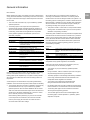 3
3
-
 4
4
-
 5
5
-
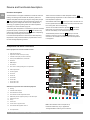 6
6
-
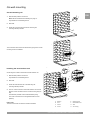 7
7
-
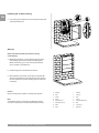 8
8
-
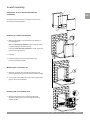 9
9
-
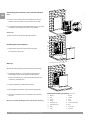 10
10
-
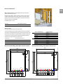 11
11
-
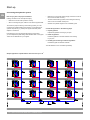 12
12
-
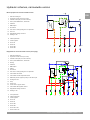 13
13
-
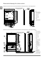 14
14
-
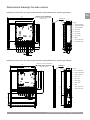 15
15
-
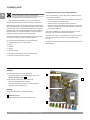 16
16
-
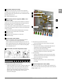 17
17
-
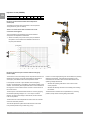 18
18
-
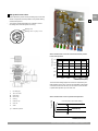 19
19
-
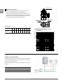 20
20
-
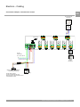 21
21
-
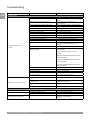 22
22
-
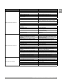 23
23
-
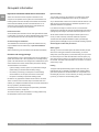 24
24
-
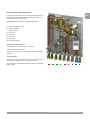 25
25
-
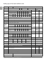 26
26
-
 27
27
-
 28
28


Uponor Combi Port B1000/S1000 Installationsanleitung
- Typ
- Installationsanleitung
in anderen Sprachen
Verwandte Papiere
Sonstige Unterlagen
-
Panasonic PAWDHWM200ZC Bedienungsanleitung
-
-
Liebert Rack Enclosure With Integrated Liquid Cooling XDK-W Benutzerhandbuch
-
Oventrop 1187095 Bedienungsanleitung
-
Chattanooga M2 Benutzerhandbuch
-
 Purmo Euro Pump Unit Bedienungsanleitung
-
Loctite 97211 Bedienungsanleitung
-
Carrera Exclusiv - Evolution Additional Supply Bedienungsanleitung
-
Bartscher A150673 Produktinformation
-
Bartscher A150671 Produktinformation
