Maico ECA piano Mounting And Operating Instructions
- Typ
- Mounting And Operating Instructions

D
GB
F
Kleinraum-Ventilator
Small Room Fan
Aérateur pour petits locaux
ECA piano
Montage- und Betriebsanleitung
Mounting and operating instructions
Instructions de montage et mode d’emploi
www.maico.de

2

3
ECA piano
1. Verwendete Warnsymbole
GEFAHR
Lebensgefahr!
Eine Nichtbeachtung kann
zum Tod oder zu schweren
Körperverletzungen führen.
VORSICHT
Verletzungsgefahr! Sachschä-
den! Eine Nichtbeachtung kann
zu leichten bis mittleren Körper-
verletzungen oder Sachschäden
führen.
2. Produktinformationen
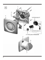
Geräteübersicht, Abb. A
1 Gehäuse mit Motor
2 Platinenträger
2.1 Klemmleiste – ECA piano STANDARD
2.2 Timerplatine – ECA piano TC
2.3 Feuchteplatine – ECA piano H
3 Motordeckel
4 Abdeckung
5 Dichtring
6 Klappe
7 Flügelrad mit Ringfeder
Ausführungen
Siehe Schaltbilder Seite 7.
ECA piano STANDARD, drehzahl-
steuerbar. Ein/Aus mit Lichtschalter oder
separatem Schalter (beide bauseitig).
Ventilator schaltet beim Betätigen des
Schalters sofort ein/aus.
ECA piano TC mit einstellbarer Nach-
laufzeit, nicht drehzahlsteuerbar.
Ein/Aus mit Lichtschalter oder separatem
Schalter (beide bauseitig). Ventilator
schaltet aus, wenn nach Betätigen des
Schalters die Nachlaufzeit abgelaufen ist.
Nachlaufzeit: ca. 3...25 min.
– ab Werk: ca. 6 min.
ECA piano H mit Feuchtesteuerung
und einstellbarer Nachlaufzeit, nicht
drehzahlsteuerbar. Funktion je nach
Anschlussvariante unterschiedlich.
Variante 1: Ventilator schaltet automatisch
ein, wenn die relative Raumfeuchte im
Bereich des Ventilators voreingestellten
Schaltpunkt überschreitet. Abschalten
erfolgt nach Unterschreiten des
Schaltpunktes und anschließendem Ablauf
einer einstellbaren Nachlaufzeit.
Mit zusätzlichem Schalter “S1“ lässt sich
der Ventilator außer Betrieb nehmen.
Variante 2: Ventilator schaltet ein – auto-
matisch per Feuchtesteuerung (gemäß
Variante 1) oder manuell per Lichtschalter.
Bei relativer Raumfeuchte über dem
Schaltpunkt lässt sich der Ventilator nicht
ausschalten, auch nicht per Lichtschalter.
Ventilator schaltet aus, wenn die Raum-
feuchte im Bereich des Ventilators unter
dem Schaltpunkt liegt und anschließend
die Nachlaufzeit abgelaufen ist.
Gilt für beide Varianten:
1. Raumfeuchte: ca. 50...90% rel. Feuchte
– ab Werk: ca. 70% rel. Feuchte
2. Nachlaufzeit: ca. 0,5...18 min.
– ab Werk: ca. 12 min.
Spannungsversorgung
Bemessungsspannung: 230 V
Netzfrequenz: 50 oder 60 Hz
3. Umgebungsbedingungen und
Grenzen für Betrieb
Zulässige Höchsttemperatur des Förder-
mediums: +40°C
Bei Betrieb mit raumluftabhängigen
Feuerstätten muss für ausreichende
Zuluftnachströmung gesorgt werden. Die
maximal zulässige Druckdifferenz pro
Wohneinheit beträgt 4 Pa.
Störfestigkeit nach DIN EN 55014-2
je nach Impulsform und Energieanteil
1000 bis 4000 V.
Bei Betrieb mit Leuchtstoffröhren sind
zusätzliche Entstörmaßnahmen erforderlich
(L-, C- oder RC-Glieder, Schutzdioden,
Varistoren), da diese Werte überschritten
werden können.
– Änderungen vorbehalten –
D

4
4. Grundlegende
Sicherheitshinweise
Allgemeine Sicherheitshinweise
Sicherheitshinweise vor Inbetriebnahme
aufmerksam durchlesen.
Anleitung aufbewahren.
Montage nur durch Fachkräfte zulässig.
Elektrischer Anschluss und Reparaturen
nur durch Elektrofachkräfte zulässig.
Gerät nur an fest verlegte elektrische
Installation mit Leitungen vom Typ NYM-O
oder NYM-J, 2 x 1,5 mm² oder 3 x 1,5 mm²
anschließen! Vorrichtung zur Trennung
vom Netz mit mind. 3 mm Kontaktöffnung
je Pol erforderlich.
Gerät nur mit auf Typenschild angegebener
Spannung und Frequenz betreiben.
Keine Veränderungen am Gerät
vornehmen.
Gerät nie ohne Abdeckung [4] betreiben.
Während des Gerätebetriebs:
Keine Gegenstände hineinstecken!
Verletzungsgefahr.
Bestimmungsgemäße Verwendung
Entlüftung von Bädern, WCs, Abstell- und
Vorratsräumen, Büros etc.
Aufputzinstallation an Wand, Decke,
Schacht oder Rohr.
Nicht bestimmungsgemäße
Verwendung
Betrieb in der Nähe von brennbaren
Materialien, Flüssigkeiten oder Gasen.
Förderung von Chemikalien, aggressiven
Gasen oder Dämpfen.
Betrieb in Einzelentlüftungsanlagen nach
DIN 18017.
5. Technische Daten
Siehe Typenschild bzw. gültigen Katalog.
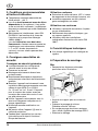
6. Montage vorbereiten
Wand
Vorgeschriebene Mindestabstände gemäß
Abbildung einhalten.
Im Bereich des Gehäuses für einen ebenen
Untergrund sorgen.
Wanddurchbruch vorbereiten.
Mindestdurchmesser 105 mm.
Bei rechteckigen Wanddurchbrüchen
Montageplatte ZM 11 verwenden!
Leitung verlegen.
VORSICHT
Kurzschlussgefahr und
Gerätebeschädigung durch
eindringendes Wasser bei
unebenem Untergrund!
Im Bereich des Dichtrings [5]
für einen ebenen Untergrund
sorgen.
Ggf. zusätzlich bauseitig
abdichten.
Decke
VORSICHT
Kurzschlussgefahr und
Gerätebeschädigung durch
Kondenswasserbildung im
Ventilatorgehäuse!
Rohrleitungen unbedingt
fachgerecht thermisch
isolieren.
– Änderungen vorbehalten –
D

5
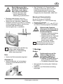
VORSICHT
Beschädigung von Netz-
leitung oder Rasthaken bei
Bohrungen in der oberen
oder unteren Seitenfläche !
Niemals die obere oder
untere Seitenfläche der
Abdeckung [4] durchbohren.
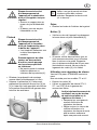
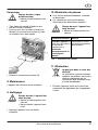
Montagevorbereitungen wie zuvor
beschrieben vornehmen (siehe Wand).
Abdeckung [4] vorbereiten. Abdeckung
entweder an Position [X] oder [Y] vorsichtig
und mit geeignetem Bohrer durchbohren,
um Nässe und Keimbildung im
Ventilatorgehäuse zu vermeiden.
Darauf achten, dass die Bohrung
mittig an den Seitenflächen
angebracht ist. Maßzeichnung
(siehe oben) beachten !
Rohr
Kanten der Rohrinnenseite entgraten!
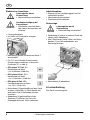
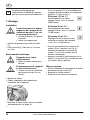
Gehäuse [1]
Gehäuserückseite auf vorhandenen
Dichtring [5] und dessen festen Sitz
überprüfen.
Ggf. Hilfsmittel (z. B. Tesamoll) zum
Fixieren in Wand oder Rohr anbringen.
Dabei Mindestabstand 20 mm zum
Stutzenende einhalten! Lagerung der
Klappen [6] nicht überkleben, siehe Pfeil!
Betrieb mit Drehzahlsteller
Nur bei ECA piano STANDARD.
Nicht zulässig für TC- und H-Ausführung!
Klappen [6] entfernen.
Drehzahlsteller STU 1, ST 1 oder STS 2,5
aus Maico-Zubehörprogramm verwenden.
VORSICHT
Stillstand und Funktions-
störung des Ventilators bei zu
geringer Ausgangsspannung
am Drehzahlsteller!
Hinweise in Betriebsanleitung
Drehzahlsteller beachten.
Mindestdrehzahl am Drehzahl-
steller immer so einstellen,
dass Motor nach Spannungs-
ausfall wieder anläuft.
Durch die Technik der Phasen-
anschnittsteuerung kann es zu
Brummgeräuschen kommen.
7. Montage
Einbau
VORSICHT
Funktionsstörung und Ge-
rätebeschädigung durch
streifendes Flügelrad [7]
bei fehlerhaftem Einbau!
Gehäuse [1] weder verspannt
noch gequetscht einbauen!
Für ebenen Untergrund sorgen.
Waagerechte Ausrichtung des Gehäuses
[1] prüfen.
Gehäuse [1] mit Schrauben (bauseitig)
befestigen.
– Änderungen vorbehalten –
i
i
D

6
Elektrischer Anschluss
GEFAHR
Lebensgefahr durch
Stromschlag!
Netzsicherung ausschalten!
VORSICHT
Gerätebeschädigung bei
Kurzschluss!
Schutzleiter und nicht benö-
tigte Adern abschneiden und
isolieren!
Leitung abmanteln.
Im Gerät nur Einzeladern verlegen.
Netzleitung gemäß Schaltbild auf Seite 7
anschließen.
Für TC- und H-Geräte Potentiometer-
Einstellungen vornehmen, siehe auch
Positionen „P“ in Abb. A.
ECA piano TC Poti „P“:
Nachlaufzeit ab Werk
= ca. 6 Minuten (9:00 Uhr)
ECA piano H Poti „P1“:
Nachlaufzeit ab Werk
= ca. 12 Minuten (12:00 Uhr)
ECA piano H Poti „P2“:
Feuchteschaltpunkt ab Werk
= ca. 70% (12:00 Uhr)
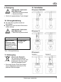
Motordeckel [3] gleichmäßig auf das Gerät
drücken (siehe Abb. A). Motordeckel fest
andrücken! Alle 5 Rasthaken müssen
einrasten.
Abdeckung [4] gleichmäßig auf das
Gehäuse [1] drücken, bis sie in die
Schnapper einrastet. Nicht verkanten!
Inbetriebnahme
Klappen [6] auf Leichtgängigkeit und Un-
versehrtheit prüfen!
Netzsicherung einschalten!
Funktionstest durchführen.
Demontage
GEFAHR
Lebensgefahr durch
Stromschlag!
Netzsicherung ausschalten!
Abdeckung [4] zuerst im unteren Drittel ab-
ziehen, dann abnehmen.
Alle 5 Rasthaken (siehe Pfeile) des Motor-
deckels [3] mit Schraubendreher aus
Rasterung drücken.
Motordeckel [3] abnehmen.
8. Instandhaltung
Das Gerät ist wartungsfrei.
– Änderungen vorbehalten –
D

7
9. Reinigung
GEFAHR
Lebensgefahr, Gerät steht
unter Spannung!
Netzsicherung ausschalten!
Gerät nicht fluten!
Gerät mit angefeuchtetem Tuch reinigen!
10. Störungsbehebung
Bei jeder Störung Elektrofachkraft
hinzuziehen!
Reparaturen sind nur durch Elektrofach-
kräfte zulässig!
GEFAHR
Lebensgefahr, Gerät steht
unter Spannung!
Netzsicherung ausschalten!
Störung Maßnahme
Gerätestillstand
oder
thermischer Über-
lastungsschutz des
Motors schaltet Gerät
aus und nach
Abkühlung wieder ein.
Störungsursache
feststellen und
beseitigen!
Tab.1: Störungsbehebung
11. Entsorgung
Nicht in den Restmüll !
Der Ventilator enthält teils
wiederverwertbare Stoffe, teils
Substanzen, die nicht in den
Restmüll gelangen dürfen.
Entsorgen Sie das Gerät nach Ablauf
seiner Lebensdauer nach den für Sie
geltenden Bestimmungen.
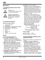
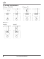
12. Schaltbilder
ECA piano STANDARD
ECA piano TC
ECA piano H
Variante 1 Variante 2
– Änderungen vorbehalten –
D

8
ECA piano
1. Warning symbols used in this
manual
DANGER
Danger of life!
If ignored, this may lead to death
or severe personal injury.
CAUTION
Danger of injury! Material
damage! If ignored, this may
lead to minor or more serious
personal injury or material
damage.
2. Product information
Device overview, Fig. A
1 Housing with motor
2 Board carrier
2.1 Terminal block – ECA piano STANDARD
2.2 Timer board – ECA piano TC
2.3 Humidity board – ECA piano H
3 Motor cover
4 Cover
5 Sealing ring
6 Shutter
7 Impeller with annular spring
Models
See wiring diagram, Page 12.
ECA piano STANDARD, speed
controllable. On/off with light switch or
separate switch (both to be supplied by the
customer). Fan switches on/off immediately
when the switch is operated.
ECA piano TC with adjustable overrun
time, not speed controllable. On/off with
light switch or separate switch (both to be
supplied by the customer). Fan switches off
immediately when the overrun time expires
after the switch has been operated.
Overrun time: approx. 3…25 min,
– factory setting: approx. 6 min.
ECA piano H, with humidity control and
adjustable overrun time, not speed
controllable. Different functions depending
on the connection version.
Version 1: The fan switches on
automatically when the relative ambient
humidity in the area of the fan exceeds the
pre-defined switching point. The fan is
switched off when the humidity level drops
below the switching point threshold and
once the defined overrun time has expired.
The fan can also be deactivated with the
optional “S1” switch.
Version 2: The fan is switched on
automatically, controlled by the humidity
level (as version 1) or manually by the light
switch. If the relative humidity level remains
above the switching point threshold, the fan
cannot be switched off, even with the light
switch. The fan switches off when the
humidity level drops below the switching
point threshold and once the defined
overrun time has expired.
Valid for both versions:
1. Ambient humidity: approx. 50…90%
relative humidity
– Factory setting: approx. 70%
relative humidity
2. Overrun time: approx. 0.5…18 min,
– Factory setting: approx. 12 min.
Power supply
Rated voltage: 230 V
Power frequency: 50 or 60 Hz
3. Environmental conditions and
operational limits
Maximum permitted airstream temperature:
+40°C
If the fans are being used with air-
ventilated fireplaces, you must ensure
that there is sufficient flow of supply air.
The maximum permitted pressure
difference per domestic unit is 4 Pa.
Resistance to interference complies with
DIN EN 55014-2, depending on the pulse
shape and energy factor 1000 to 4000 V
If operating with fluorescent tube lighting,
additional interference suppression
measures (L, C components or RC
modules, protection diodes, varistors) are
needed, as these values can be exceeded.
– Subject to change –
GB

9
4. Basic safety instructions
General notes regarding safety
Read the following safety instructions
carefully before starting to work with the
unit.
Please keep these instructions somewhere
safe.
Assembly should only be carried out by
expert personnel.
Electrical connections and repairs should
only be carried out by trained electricians.
Only connect to a fixed electrical
installation with type NYM-O or NYM-J
cables, 2 x 1.5 mm
2
or 3 x 1.5 mm
2
. A
mains isolation device that has contact
openings of at least 3 mm at each pole is
required.
The fan should only be operated using the
rated voltage and power frequency
indicated on the rating plate.
Do not carry out any modifications to the
device.
Never operate the device without the cover
[4] in place.
While the device is in operation:
Never insert any objects. Danger of injury.
Intended use
Extracting air from bathrooms, toilets,
storage rooms or larders, offices, etc.
Surface installation on walls, ceilings,
shafts or ducting.
Improper use
Operation in the vicinity of combustible
materials, fluids or gases.
Transport of chemicals, gases or vapours.
Operation in single air extraction systems
in accordance with DIN 18017.
5. Technical Data
See the rating plate or the currently valid
catalogue.
6. Installation preparation
Wall
Maintain the minimum spacings according
to the picture.
Make sure there is a flat surface to mount
the housing on.
Prepare the wall breakthrough.
Minimum diameter is 105 mm.
Use a ZM11 mounting plate, with
rectangular wall breakthroughs.
Lay the cables.
CAUTION
If the surface is uneven, there
is a danger of short circuits
and damage to the device if
water can penetrate the
housing!
Make sure there is a flat
surface in the area of the
sealing ring [5].
If necessary, provide
additional sealing measures.
Ceiling
CAUTION
There is a danger of short
circuits and damage to the
device if condensate forms
in the fan housing!
Ensure that ducts are correctly
thermally insulated.
– Subject to change –
GB

10
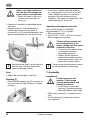
CAUTION
Holes in the top or bottom of
the side face will damage the
power cable or locking hook
!
Never drill holes in the top or
bottom of the side faces of
cover [4].
Prepare for assembly as described above
(see wall).
Prepare cover [4]. Use suitable drill to
carefully drill holes in cover, either at
position [X] or [Y] to prevent dampness and
germs from building up in the fan housing.
Ensure that the hole is in the centre of
the side face. Observe dimensions
shown in drawing (above).
Duct
Deburr the inside edges of the duct.
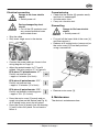
Housing [1]
Check that the sealing ring [5] is present at
the rear of the housing and that it is seated
correctly.
If necessary, supply additional material,
e.g. sealing tape to fix the unit to the wall
or duct. Make sure there is a minimum
distance of 20 mm to the end of the
connector. Don’t apply any adhesive to the
shutter bearing [6], see arrow.
Operation with speed controller
Only with ECA piano STANDARD.
Not permitted for TC or H models.
Remove shutters [6].
Use an STU 1, ST 1 or STS 2,5 from the
Maico range of accessories.
CAUTION
The fan will not operate and
cause malfunctions if the
output voltage from the speed
controller is too low!
Take note of the advice given
in the speed controller
operating instructions.
Always set the minimum
speed at the speed controller,
such that the motor starts up
again after a power failure.
There can be vibration noises caused
by the phase control technology.
7. Assembly
Installation
CAUTION
If fitted incorrectly, the
impeller [7] will scrape
causing malfunctions and
damage the device!
Do not twist or distort the
housing [1] during installation.
Make sure there is a flat surface.
Check that housing [1] is aligned horizon-
tally.
Fix the housing [1] in place with screws
(not supplied).
– Subject to change –
i
i
GB

11
Electrical connection
DANGER
Danger to life from electric
shock!
Switch power off.
CAUTION
Device damaged by short
circuit!
Cut off the PE conductor and
any unused individual cores
and insulate them.
Strip the cable.
Only insert single cores in the device.
Connect the power cable as shown in the
wiring diagram on Page 12.
Adjust the potentiometer for TC and H
models. See also position “P” in Figure A.
ECA piano TC potentiometer “P”:
Factory set overrun time
= approx. 6 minutes (9 o’clock)
ECA piano H potentiometer “P1”:
Factory set overrun time
= approx. 12 minutes (12 o’clock)
ECA piano H potentiometer “P2”:
Factory set humidity switching point
= approx. 70% (12 o’clock)
Press the motor cover [3] evenly and se-
curely into place on the device (see Fig. A).
All 5 locking hooks must clip into place.
Press the cover [4] evenly over the housing
[1] until it clicks into place. Do not bend or
distort it.
Commissioning
Check that the shutter [6] operates easily
and that it is undamaged.
Activate mains fuse.
Carry out a function test.
Dismantling
DANGER
Danger to life from electric
shock!
Switch power off.
First pull off the lower third of the cover [4]
and then remove it.
Release all 5 locking hooks (see arrow] on
the motor cover [3] from their positions
using a screwdriver.
Remove motor cover [3].
8. Maintenance
The device is maintenance-free.
– Subject to change –
GB

12
9. Cleaning
DANGER
Danger to life, the device
is live!
Switch power off.
Don’t apply water to the
device.
Clean the device with a moist cloth.
10. Fault rectification
Always call on the services of a qualified
electrician in the case of faults.
Repairs should only be carried out by
trained electricians.
DANGER
Danger to life, the device
is live!
Switch power off.
Fault Measure
Device doesn’t run
or
thermal overload
motor protection
switches the device
off and back on again
after it cools down.
Identify the cause of
the fault and rectify it.
Tab. 1: Fault rectification
11. Disposal
Do not dispose of
in the rubbish!
The fan contains some
recyclable materials and some
substances that should not be
disposed of in the rubbish.
After its lifetime has elapsed, dispose of the
device according to the valid regulations.
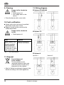
12. Wiring diagram
ECA piano STANDARD
ECA piano TC
ECA piano H
Version 1 Version 2
– Subject to change –
GB

13
ECA piano
1. Symboles d'avertissement
utilisés
DANGER
Risque de blessure!
Le non respect peut entraîner
la mort ou des blessures
graves.
ATTENTION
Risque de blessure/Dommages
matériels ! Le non respect peut
entraîner des blessures légères
à moyennement graves ou des
dommages matériels.
2. Informations produit
Vue d'ensemble de l'appareil, Fig. A
1 Boîtier avec moteur
2 Porte-platine
2.1 Réglette de bornier - ECA piano
STANDARD
2.2 Platine Timer – ECA piano TC
2.3 Platine humidité – ECA piano H
3 Couvercle moteur
4 Cache de protection
5 Joint d'étanchéité
6 Volet
7 Hélice avec anneau-ressort
Modèles
Voir schémas de branchement page 18.
ECA piano STANDARD, à vitesse
variable. Marche/Arrêt avec interrupteur
d'éclairage ou interrupteur séparé (les deux
à fournir par le client). Le ventilateur se met
immédiatement en marche/arrêt si l'on
actionne l'interrupteur.
ECA piano TC avec fonctionnement par
inertie réglable, vitesse non réglable
Marche/Arrêt avec interrupteur d'éclairage
ou interrupteur séparé (les deux à fournir
par le client). Le ventilateur s'arrête après
l'actionnement de l'interrupteur dès que le
temps de fonctionnement par inertie est
écoulé.
Fonctionnement par inertie : env. 3...25 min.
– réglage d'usine : env. 6 min.
ECA piano H avec commande en
fonction de l'humidité et fonctionnement
par inertie réglable, vitesse non réglable
Fonction différente selon la variante de
connexion.
Variante 1 : Le ventilateur se met auto-
matiquement en marche dès que l'humidité
ambiante dans la zone du ventilateur
dépasse le point de commutation. L'arrêt
se fait si l'humidité est inférieure au point
de commutation et une fois le temps de
fonctionnement par inertie écoulé.
Un interrupteur supplémentaire "S1"
permet d'arrêter le ventilateur.
Variante 2 : La mise en marche du
ventilateur se fait automatiquement via la
commande en fonction de l'humidité (selon
Variante 1) ou manuellement par
l'interrupteur d'éclairage.
Si l'humidité relative est supérieure au
point de commutation, il est impossible
d'arrêter le ventilateur, même avec
l'interrupteur d'éclairage. Le ventilateur
s'arrête si l'humidité ambiante dans la zone
du ventilateur est inférieure au point de
commutation et une fois le temps du
fonctionnement par inertie écoulé.
S´applique aux deux variantes :
1. Humidité ambiante :
env. 50 ... 90 % d'humidité rel.
– réglage d'usine :
env. 70 % d'humidité rel.
2. Fonctionnement par inertie :
env. 0,5 ... 18 min.
– réglage d'usine :
env. 12 min.
Alimentation électrique
Tension de service : 230 V
Fréquence du secteur : 50 ou 60 Hz
– Sous réserve de modification –
F

14
3. Conditions environnementales
et limites d'utilisation
Température maximale admissible du
fluide refoulé : +40 °C
Lors d'un fonctionnement avec des âtres
dépendants de l'air ambiant, il faut veiller
à une arrivée d'air suffisante. La différence
de pression maximale par unité d'habitation
est de 4 Pa.
Résistance aux interférences selon DIN
EN 55014-2 en fonction de la forme de
l'impulsion et la proportion d'énergie
1000 à 4000 V.
Lors de l'utilisation avec des tubes
fluorescents, d'autres mesures contre les
interférences sont nécessaires (éléments
L, C ou RC, diodes de protection,
varistors), car ces valeurs peuvent être
dépassées.
4. Consignes essentielles de
sécurité
Consignes de sécurité générales
Lire attentivement les consignes de
sécurité avant la mise en service.
Conserver le manuel.
Montage exclusivement réservé aux
professionnels.
Branchement électrique et réparations
exclusivement réservés à des électriciens
qualifiés.
Brancher l'appareil exclusivement à une
installation électrique permanente avec des
câbles du type NYM-O ou NYM-J,
2 x 1,5 mm² ou 3 x 1,5 mm² ! Dispositif
pour la coupure du secteur avec une
ouverture de contact d'au moins 3 mm
par pôle nécessaire.
Utiliser l'appareil exclusivement avec la
tension et fréquence indiquées sur la
plaque signalétique.
N'effectuer aucune modification sur
l'appareil.
Ne jamais utiliser l'appareil [4] sans le
cache de protection.
Pendant que l'appareil est en service :
n'introduire aucun objet à l'intérieur!
Risque de blessure.
Utilisation conforme
Extraction de salles de bains, WC´s, locaux
de rangement et de stockage, bureaux, etc.
Installation apparente au mur, plafond,
gaine rectangulaire ou ronde.
Utilisation non conforme
Utilisation à proximité de matières, liquides
ou gaz inflammables.
Refoulement de produits chimiques, gaz
ou vapeurs agressifs.
Utilisation dans des installations
individuelles d'extraction d'air selon DIN
18017.
5. Caractéristiques techniques
Voir plaque signalétique ou catalogue en
vigueur.
6. Préparation du montage
Mur
Respecter les distances minimales
prescrites selon l'illustration.
Assurer un support plan au niveau du
boîtier.
Préparer le perçage de cloison.
Diamètre minimal 105 mm.
En cas de perçage de cloison rectangu-
laire, utiliser la platine de montage ZM 11.
Effectuer le câblage.
– Sous réserve de modification –
F

15
ATTENTION
Risque de court-circuit et
d’endommagement de
l’appareil par la pénétration
d’eau si le support n’est pas
régulier!
Assurer un support plan au
niveau du joint d'étanchéité
[5].
Si besoin, assurer en plus
l'étanchéité sur site.
Plafond
ATTENTION
Risque de court-circuit et
d’endommagement de
l’appareil par la formation
d’eau de condensation dans
le boîtier de l’appareil !
Il est impératif d’effectuer une
isolation thermique des
conduits.
ATTENTION
Endommagement du câble
secteur ou des crochets
d’arrêt en cas de perçage
sur la surface supérieure
ou inférieure !
Ne jamais percer la surface
latérale supérieure ou
inférieure de la protection [4].
Effectuer les préparatifs de montage
comme décrit précédemment (cf. mur).
Préparer la protection [4]. Percer avec
précaution la protection en position [X] ou
[Y] à l’aide d’un forêt approprié afin d’éviter
la formation d’humidité et de germes dans
le boîtier du ventilateur.
Veiller à ce que la percée soit bien
située au milieu des surfaces
latérales. Respecter le dessin coté
(cf. ci-dessus) !
Gaine
Ébarber les bords de l'intérieur de la gaine!
Boîtier [1]
Vérifiez au dos de l'appareil la présence et
la bonne tenue du joint d'étanchéité [5].
Si besoin, utiliser des auxiliaires (par ex.
joint mousse autocollant) pour la fixation
dans la cloison ou la gaine. Respecter
alors la distance minimale de 20 mm avec
l'extrémité du raccord. Ne pas coller le
logement des volets [6], voir flèche!
Utilisation avec régulateur de vitesse
Version ECA piano STANDARD exclusive-
ment.
Non autorisée pour les modèles TC et H !
Enlever les volets [6].
Utiliser un régulateur de vitesse STU 1,
ST 1 ou STS 2,5 de la gamme des
accessoires Maico.
ATTENTION
Arrêt et dysfonctionnement du
ventilateur en cas de tension
de sortie trop faible sur le
régulateur de vitesse !
Respecter les consignes du
manuel d'utilisation du
régulateur de vitesse.
Régler toujours la vitesse de
rotation minimale sur le
régulateur de vitesse de sorte
que le moteur redémarre
après une panne de courant.
– Sous réserve de modification –
i
F

16
La technique de réglage par
redressement à l'entrée des phases
peut provoquer des bourdonnements.
7. Montage
Installation
ATTENTION
Dysfonctionnement et endom-
magement de l’appareil dû au
frottement du rotor [7] en cas
de montage défectueux!
Installer le boîtier [1] ni gauchi
ni coincé!
Veiller à un support plan.
Vérifier l'alignement horizontal du boîtier
[1].
Fixer le boîtier [1] avec des vis (à fournir
sur site).
Branchement électrique
DANGER
Danger de mort, risque
d’électrocution!
Mettre le fusible secteur hors
service!
ATTENTION
Endommagement de l’appareil
en cas de court-circuit!
Couper et isoler le conducteur
de protection et des fils non
utilisés!
Blinder les câbles.
Câbler uniquement des conducteurs
individuels dans l'appareil.
Brancher le câble secteur selon le schéma
de branchement à la page 18.
Pour les appareils TC et H, procéder aux
réglages de potentiomètre, voir également
positions "P“ dans la Fig. A.
ECA piano TC Poti "P":
Fonctionnement par inertie
réglage d'usine = env. 6 minutes
(9:00 heures)
ECA piano H Poti "P1" :
Fonctionnement par inertie
réglage d'usine = env. 12 minutes
(12:00 heures)
ECA piano H Poti "P2" :
Réglage d'usine du point de com-
mutation en fonction de l'humidité
= env. 70 % (12:00 heures)
Presser uniformément le couvercle du
moteur [3] sur l'appareil (voir Fig. A).
Appuyer fermement le couvercle du
moteur ! Touts les 5 crochets d'arrêt
doivent s'enclencher.
Appuyer le cache [4] uniformément sur le
boîtier [1] jusqu'à ce qu'il s'enclenche dans
les loquets. Ne pas gauchir!
Mise en service
Vérifier l'absence de dommage et la facilité
de manœuvre des volets [6] !
Brancher le fusible secteur !
Effectuer un test de fonctionnement.
– Sous réserve de modification –
i
F

17
Démontage
DANGER
Danger de mort, risque
d’électrocution!
Mettre le fusible secteur hors
service!
Tirer d'abord le cache [4] dans le tiers
inférieur avant le l'enlever.
Pousser tous les 5 crochets d'arrêt (voir
flèches) du couvercle du moteur [3] avec
un tournevis hors des loquets.
Enlever le couvercle du moteur [3].
8. Maintenance
L'appareil ne nécessite aucun entretien.
9. Nettoyage
DANGER
Danger de mort, l’appareil est
sous tension!
Mettre le fusible secteur hors
service!
Ne pas mettre l'appareil dans
l'eau!
Nettoyer l'appareil avec un chiffon
humidifié.
10. Élimination de pannes
Lors de tout dysfonctionnement, consulter
un électricien !
Les réparations sont exclusivement
réservées à des électriciens qualifiés !
DANGER
Danger de mort, l’appareil est
sous tension!
Mettre le fusible secteur hors
service!
Dysfonctionnement Mesure
Arrêt de l'appareil ou
mise hors service puis
en service de
l'appareil par la
protection
thermique contre la
surcharge du
moteur.
Déterminer la cause
du dysfonctionnement
puis l'éliminer.
Tab. 1: Élimination de pannes
11. Élimination
Ne pas jeter dans le reste des
déchets!
Le ventilateur contient certaines
matières recyclables, mais aussi
d'autres substances qui ne
doivent pas être éliminées avec
le reste des déchets.
Éliminez l'appareil arrivé en fin de vie en
respectant les règlements qui s'appliquent
à vous.
– Sous réserve de modification –
F

18
12. Schémas de branchement
ECA piano STANDARD
ECA piano H
Variante 1 Variante 2
ECA piano TC
– Sous réserve de modification –
F

19

20
MAICO Elektroapparate-Fabrik GmbH • Steinbeisstr. 20 • 78056 Villingen-Schwenningen •
Deutschland • Service-Hotline 0049 – (0)1805 694 110 • E-Mail: [email protected]
0185.1111.0001 / 09.06
-
 1
1
-
 2
2
-
 3
3
-
 4
4
-
 5
5
-
 6
6
-
 7
7
-
 8
8
-
 9
9
-
 10
10
-
 11
11
-
 12
12
-
 13
13
-
 14
14
-
 15
15
-
 16
16
-
 17
17
-
 18
18
-
 19
19
-
 20
20


Maico ECA piano Mounting And Operating Instructions
- Typ
- Mounting And Operating Instructions
in anderen Sprachen
- English: Maico ECA piano
- français: Maico ECA piano
Verwandte Artikel
-
Maico ECA piano STANDARD Mounting And Operating Instructions
-
-
-
-
-
-
-
-