
Montage- und Betriebsanleitung
Kleinraumventilatoren
Mounting and Operating instructions
Small room fans
Instructions de montage et Mode d’emploi
Aérateurs pour petites pièces
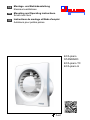
ECA piano
STANDARD
ECA piano TC
ECA piano H
B
www.maico- ventilatoren.com
DE
UK
FR

2

Lieferumfang │ DE
3
ECA piano
Lieferumfang 1.
ECA-Kleinraumventilator, Dichtring, Betriebs-
anleitung. Schaumstoffband bei ECA piano H.
Verwendete Symbole 2.
2.1 Warnsymbole
GEFAHR
Lebensgefahr!
Eine Nichtbeachtung kann
zum Tod oder zu schweren
Körperverletzungen führen.
VORSICHT
Verletzungsgefahr!
Eine Nichtbeachtung kann zu
leichten bis mittleren Körper-
verletzungen führen.
ACHTUNG
Sachschäden!
Eine Nichtbeachtung kann zu
Sachschäden führen.
2.2 Sonstige Symbole
INFO-Symbol: Mit diesem
Symbol versehene Text-
passagen geben Ihnen wichtige
Informationen und Tipps.
● Aufzählungssymbol:
Liste mit wichtigen Informatio-
nen zum jeweiligen Thema.
Handlungssymbol:
Liste mit durchzuführenden
Tätigkeiten. Führen Sie die
angegebenen Anweisungen
der Reihe nach durch.
Produktinformationen 3.
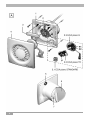
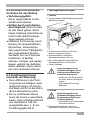
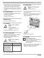
3.1 Geräteübersicht, Abb. A
1 Gehäuse mit Motor
2 Platinenträger
2.1 Klemmleiste – ECA piano STANDARD
2.2 Timerplatine – ECA piano TC
2.3 Feuchteplatine – ECA piano H
3 Motordeckel
4 Abdeckung
5 Dichtring
6 Klappe
7 Flügelrad mit Ringfeder
3.2 Produktbeschreibung
ECA piano STANDARD, drehzahlsteuerbar.
Ein/Aus mit Lichtschalter oder separatem
Schalter (beide bauseitig). Ventilator schaltet
beim Betätigen des Schalters sofort ein/aus.
ECA piano TC mit einstellbarer Nach-
laufzeit, nicht drehzahlsteuerbar. Ein/Aus mit
Lichtschalter oder separatem Schalter (beide
bauseitig). Ventilator schaltet aus, wenn nach
Betätigen des Schalters die Nachlaufzeit
abgelaufen ist.
Nachlaufzeit: ca. 3...25 min.
– ab Werk: ca. 6 min.
ECA piano H mit Feuchtesteuerung
und einstellbarer Nachlaufzeit, nicht
drehzahlsteuerbar. Funktion je nach
Anschlussvariante unterschiedlich.
Variante 1: Ventilator schaltet automatisch
ein, wenn die relative Raumfeuchte im
Bereich des Ventilators voreingestellten
Schaltpunkt überschreitet. Abschalten erfolgt
nach Unterschreiten des Schaltpunktes und
anschließendem Ablauf einer einstellbaren
Nachlaufzeit.
Mit zusätzlichem Schalter “S1“ lässt sich der
Ventilator außer Betrieb nehmen.
Variante 2: Ventilator schaltet ein – auto-
matisch per Feuchtesteuerung (gemäß
Variante 1) oder manuell per Lichtschalter.
Bei relativer Raumfeuchte über dem
Schaltpunkt lässt sich der Ventilator nicht
ausschalten, auch nicht per Lichtschalter.
Ventilator schaltet aus, wenn die Raum-
feuchte im Bereich des Ventilators unter dem
Schaltpunkt liegt und anschließend die
Nachlaufzeit abgelaufen ist.
Gilt für beide Varianten:
1. Raumfeuchte: ca. 50...90% rel. Feuchte
– ab Werk: ca. 70% rel. Feuchte
2. Nachlaufzeit: ca. 0,5...18 min.
– ab Werk: ca. 12 min.
Impressum: © MAICO Elektroapparate-Fabrik GmbH.
Deutsche Original-Betriebsanleitung. Druckfehler,
Irrtümer und technische Änderungen vorbehalten.
i
●
DE

DE │ Bestimmungsgemäße Verwendung
4
3.3 Bestimmungsgemäße
Verwendung
● Dieses Gerät ist ausschließlich für den
häuslichen Gebrauch und ähnliche Zwecke
vorgesehen.
● Das Gerät dient zur Entlüftung von Bädern,
WCs, Abstell- und Vorratsräumen, Ausstel-
lungsräumen, Keller, Büros, Gemeinschafts-
duschen in Vereinsheimen, Fitnessstudios,
Umkleidekabinen und ähnlichen Räumen.
● Zulässig ist ein Betrieb nur bei:
● Festinstallation innerhalb von Gebäuden.
● Installation an Wand oder Decke.
● Luftführung über Schacht oder Rohr.
● elektrischem Unterputz-Anschluss.
3.4 Vorhersehbare Fehlanwendungen
Maico haftet nicht für Schäden durch bestim-
mungswidrigen Gebrauch. Gerät auf keinen
Fall einsetzen:
● in Einzelentlüftungsanlagen nach
DIN 18017-3.
● in der Nähe von brennbaren Materialien,
Flüssigkeiten oder Gasen.
● für die Förderung von Chemikalien,
aggressiven Gasen oder Dämpfen.
● in explosionsfähiger Atmosphäre.
● im Außenbereich.
Technische Daten 4.
● Siehe Typenschild.
Umgebungsbedingungen und 5.
Grenzen für Betrieb
● Zulässige Höchsttemperatur des Förder-
mediums: + 40 °C
● Bei Betrieb mit raumluftabhängigen
Feuerstätten muss für ausreichende
Zuluftnachströmung gesorgt werden. Die
maximal zulässige Druckdifferenz pro
Wohneinheit beträgt 4 Pa.
● Störfestigkeit nach EN 55014-2 je nach
Impulsform und Energieanteil 1000 bis
4000 V. Bei Betrieb mit Leuchtstoff-
röhren sind zusätzliche Entstörmaßnah-
men erforderlich (L-, C- oder RC-Glieder,
Schutzdioden, Varistoren), da diese Werte
überschritten werden können.
Sicherheitshinweise 6.
6.1 Allgemeine
Sicherheitshinweise
● Sicherheitshinweise vor
Inbetriebnahme aufmerksam
durchlesen.
● Anleitung aufbewahren.
● Montage nur durch Fachkräfte
zulässig.
● Elektrischer Anschluss und
Reparaturen nur durch
Elektrofachkräfte zulässig.
● Gerät nur an fest verlegte
elektrische Installation mit
Leitungen vom Typ NYM-O
oder NYM-J, 2 x 1,5 mm² oder
3 x 1,5 mm² anschließen.
Vorrichtung zur Trennung vom
Netz mit mind. 3 mm Kontakt-
öffnung je Pol erforderlich.
● Gerät nur mit auf Typenschild
angegebener Spannung und
Frequenz betreiben.
● Keine Veränderungen am
Gerät vornehmen.
● Gerät nie ohne Abdeckung [4]
betreiben.

Sicherheitshinweise │ DE
5
6.2 Sicheres und korrektes
Verhalten für den Betrieb
● Verletzungsgefahr.
Keine Gegenstände in das
Gerät hineinstecken.
● Gefahr durch sich drehen-
des Flügelrad. Nicht zu nahe
an das Gerät gehen, damit
Haare, Kleidung oder Schmuck
nicht in das Gerät hineinge-
zogen werden können.
● Gefahren für Personen (auch
Kinder) mit eingeschränkten
physischen, sensorischen
oder psychischen Fähigkeiten
oder mangelndem Wissen.
Ventilator nur von Personen
installieren, in Betrieb
nehmen, reinigen und warten
lassen, welche die Gefahren
dieser Arbeiten sicher erken-
nen und vermeiden können.
6.3 Zuluftnachströmung
innerhalb der Wohnung
● Die Luftführung in der Woh-
nung muss so erfolgen, dass
möglichst keine Luft aus Kü-
che, Bad und WC in die Wohn-
räume überströmen kann.
● Ein zu entlüftender Raum
muss mit einem unverschließ-
baren, freien Zuluftquerschnitt
von mindestens 150 cm²
ausgestattet sein, z. B. mit
Türlüftungsgitter MLK.
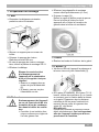
Montagevorbereitungen 7.
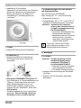
7.1 Wand
Vorgeschriebene Mindestabstände gemäß
Abbildung einhalten.
Im Bereich des Gehäuses für einen
ebenen Untergrund sorgen.
Wanddurchbruch vorbereiten.
Mindestdurchmesser 105 mm.
Bei rechteckigen Wanddurchbrüchen
Montageplatte ZM 11 verwenden!
Leitung verlegen.
VORSICHT
Kurzschlussgefahr und
Gerätebeschädigung durch
eindringendes Wasser bei
unebenem Untergrund!
Im Bereich des Dichtrings [5]
für einen ebenen Untergrund
sorgen.
Ggf. zusätzlich bauseitig
abdichten.
7.2 Decke
VORSICHT
Kurzschlussgefahr und
Gerätebeschädigung durch
Kondenswasserbildung im
Ventilatorgehäuse!
Lüftungsleitungen fachgerecht
thermisch isolieren.
Montagevorbereitungen wie zuvor
beschrieben vornehmen (siehe Wand).

DE │ Montagevorbereitungen
6
Abdeckung [4] vorbereiten.
Abdeckung vor dem Bohren vom Gehäuse
abnehmen. Abdeckung mit geeignetem
Bohrer durchbohren, um Nässe und
Keimbildung im Ventilatorgehäuse zu
vermeiden.
7.3 Rohr
Kanten der Rohrinnenseite entgraten!
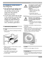
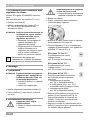
7.4 Gehäuse [1]
Gehäuserückseite auf vorhandenen
Dichtring [5] und dessen festen Sitz
überprüfen.
ECA piano STANDARD, ECA piano TC:
Ggf. Hilfsmittel (z. B. Schaumstoffband) zum
Fixieren in Wand oder Rohr anbringen.
Dabei Mindestabstand 20 mm zum
Stutzenende einhalten! Lagerung der
Klappen [6] nicht überkleben, siehe Pfeil!
ECA piano H:
Schaumstoffband wie zuvor beschrieben
anbringen. Dies ist wichtig, damit das
Gerät keine Luft von Außen anzieht.
7.5 Vorbereitungen für den Betrieb
mit Drehzahlsteller
Nur bei ECA piano STANDARD.
Nicht zulässig für TC- und H-Ausführung.
Klappen [6] entfernen.
Drehzahlsteller STU 1, ST 1 oder STS 2,5
aus Maico-Zubehörprogramm verwenden.
ACHTUNG
Stillstand und Funktions-
störung des Ventilators bei zu
geringer Ausgangsspannung
am Drehzahlsteller.
Hinweise in Betriebsanleitung
Drehzahlsteller beachten.
Mindestdrehzahl am Drehzahl-
steller immer so einstellen,
dass Motor nach Spannungs-
ausfall wieder anläuft.
Durch die Technik der Phasen-
anschnittsteuerung kann es zu
Brummgeräuschen kommen.
Montage 8.
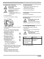
8.1 Einbau
ACHTUNG
Funktionsstörung und Ge-
rätebeschädigung durch
streifendes Flügelrad [7]
bei fehlerhaftem Einbau!
Gehäuse [1] weder verspannt
noch gequetscht einbauen!
Für ebenen Untergrund sorgen.
Waagerechte Ausrichtung des Gehäuses
[1] prüfen.
Gehäuse [1] mit Schrauben (bauseitig)
befestigen.
i

Montage / Elektrischer Anschluss │ DE
7
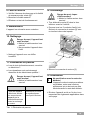
8.2 Elektrischer Anschluss
GEFAHR
Lebensgefahr durch
Stromschlag.
Netzsicherung ausschalten!
VORSICHT
Gerätebeschädigung bei
Kurzschluss.
Schutzleiter und nicht
benötigte Adern abschneiden
und isolieren.
Leitung abmanteln.
Im Gerät nur Einzeladern verlegen.
Netzleitung gemäß Schaltbild auf Seite 20
anschließen.
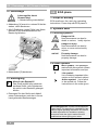
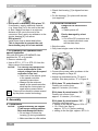
Für TC- und H-Geräte Potentiometer-
Einstellungen vornehmen, siehe auch
Positionen „P“ in Abb. A.
ECA piano TC Poti „P“:
Nachlaufzeit ab Werk
ca. 6 Minuten (9:00 Uhr)
ECA piano H Poti „P1“:
Nachlaufzeit ab Werk
ca. 12 Minuten (12:00 Uhr)
ECA piano H Poti „P2“:
Feuchteschaltpunkt
ganz links, ca. 50 % r.F.
12:00 Uhr (siehe Abbildung):
ca. 70 % r.F. (ab Werk)
ganz rechts, ca. 90 % r.F.
Motordeckel [3] gleichmäßig auf das Gerät
drücken (siehe Abb. A). Motordeckel fest
andrücken! Alle 5 Rasthaken müssen
einrasten.
Abdeckung [4] gleichmäßig auf das
Gehäuse [1] drücken, bis sie in die
Schnapper einrastet. Nicht verkanten!
8.3 Inbetriebnahme
Klappen [6] auf Leichtgängigkeit und
Unversehrtheit prüfen!
Netzsicherung einschalten!
Funktionstest durchführen.
Wartung 9.
Das Gerät ist wartungsfrei.
Reinigung 10.
GEFAHR
Lebensgefahr, Gerät steht
unter Spannung!
Netzsicherung ausschalten!
Gerät mit angefeuchtetem Tuch reinigen!
Störungsbehebung 11.
● Bei jeder Störung Elektrofachkraft
hinzuziehen!
● Reparaturen sind nur durch Elektrofach-
kräfte zulässig!
GEFAHR
Lebensgefahr, Gerät steht
unter Spannung!
Netzsicherung ausschalten!
Störung
Maßnahme
– Gerätestillstand
– Thermischer Über-
lastungsschutz des
Motors schaltet Gerät
aus und nach
Abkühlung wieder ein.
Störungsursache
feststellen und
beseitigen!
Tab.1: Störungsbehebung

DE │ Demontage / UK │Scope of delivery
8
Demontage 12.
GEFAHR
Lebensgefahr durch
Stromschlag!
Netzsicherung ausschalten!
Abdeckung [4] zuerst im unteren Drittel ab-
ziehen, dann abnehmen.
Alle 5 Rasthaken (siehe Pfeile) des Motor-
deckels [3] mit Schraubendreher aus
Rasterung drücken.
Motordeckel [3] abnehmen.
Entsorgung 13.
Nicht in den Restmüll !
Das Gerät enthält teils wiederver-
wertbare Stoffe, teils Substanzen,
die nicht in den Restmüll gelangen
dürfen.
Entsorgen Sie das Gerät nach Ablauf
seiner Lebensdauer nach den in Ihrem
Land geltenden Bestimmungen.
ECA piano
1. Scope of delivery
ECA small room fan, seal ring, operating
instructions. Foam strip with ECA piano H.
Symbols used 2.
2.1 Warning symbols
DANGER
Danger to life.
Non-observance can lead to
death or serious bodily injuries.
CAUTION
Danger of injury.
Non-observance can lead to
minor or more serious bodily
injuries.
NOTICE
Property damage.
Non-observance can lead to
property damage.
2.2 Other symbols
INFO symbol: Text passages
marked with this symbol contain
important information and tips.
● List symbol:
List containing important infor-
mation on the relevant subject.
Action symbol: List of work
to be carried out. Follow the
instructtions in the order given.
i
i
Ï
Acknowledgements: © MAICO Elektroapparate-
Fabrik GmbH. This instruction is a translation of the
German original operating instructions. We cannot
be held responsible for mistakes or printing
errors and retain the right to make technical
modifications without giving prior notice.
UK

Product information │ UK
9
Product information 3.
3.1 Device overview, Fig. A
1 Housing with motor
2 Board carrier
2.1 Terminal block – ECA piano STANDARD
2.2 Timer board – ECA piano TC
2.3 Humidity board – ECA piano H
3 Motor cover
4 Cover
5 Sealing ring
6 Shutter
7 Impeller with annular spring
3.2 Product description
● ECA piano STANDARD, speed
controllable. On/off with light switch or
separate switch (both to be supplied by the
customer). Fan switches on/off immediately
when the switch is operated.
● ECA piano TC with adjustable overrun
time, not speed controllable. On/off with
light switch or separate switch (both to be
supplied by the customer). Fan switches off
immediately when the overrun time expires
after the switch has been operated.
Overrun time: approx. 3 … 25 min,
– factory setting: approx. 6 min.
● ECA piano H, with humidity control and
adjustable overrun time, not speed
controllable. Different functions depending
on the connection version.
Version 1: The fan switches on
automatically when the relative ambient
humidity in the area of the fan exceeds the
pre-defined switching point. The fan is
switched off when the humidity level drops
below the switching point threshold and
once the defined overrun time has expired.
The fan can also be deactivated with the
optional “S1” switch.
Version 2: The fan is switched on
automatically, controlled by the humidity
level (as version 1) or manually by the light
switch. If the relative humidity level remains
above the switching point threshold, the fan
cannot be switched off, even with the light
switch. The fan switches off when the
humidity level drops below the switching
point threshold and once the defined
overrun time has expired.
Valid for both versions:
1. Ambient humidity:
approx. 50 … 90 % relative humidity
Factory setting:
approx. 70% relative humidity
2. Overrun time: approx. 0.5 … 18 min,
Factory setting: approx. 12 min
3.3 Intended use
● This fan is only intended for domestic use
and similar purposes.
● Fan for extracting air from bathrooms, toilet
rooms, storage rooms, showrooms, cellars,
offices, communal showers in clubhouses,
fitness studios, changing rooms and similar
places.
● An operation is only permitted when:
● permanent installation in buildings.
● installation on walls or ceilings.
● air supply via shaft or pipe.
● recessed mounted electrical connection.
3.4 Predictable misuses
Maico is not liable for damages caused by
use contrary to the intended purpose. Under
no circumstances should the unit be used:
● in single air extraction systems according to
DIN 18017-3.
● close to flammable materials, liquids or
gases.
● for the conveying of chemicals, aggressive
gases or vapours.
● in potentially explosive atmospheres
● outdoors.
Technical Data 4.
● See rating plate.
Environmental conditions and 5.
operational limits
● Maximum permitted airstream temperature:
+40 °C

UK │ Environmental conditions and operational limits
10
● If the fans are being used with air-
ventilated fireplaces, you must ensure
that there is sufficient flow of supply air.
The maximum permitted pressure
difference per domestic unit is 4 Pa.
● Resistance to interference complies with
EN 55014-2, depending on the pulse
shape and energy factor 1000 to 4000 V. If
operating with fluorescent tube lighting,
additional interference suppression
measures (L, C components or RC
modules, protection diodes, varistors) are
needed, as these values can be exceeded.
Safety instructions 6.
6.1 General notes regarding
safety
● Read the following safety
instructions carefully before
starting to work with the unit.
● Please keep these instructions
somewhere safe.
● Assembly should only be car-
ried out by expert personnel.
● Electrical connections and
repairs should only be carried
out by trained electricians.
● Only connect to a fixed elec-
trical installation with type
NYM-O or NYM-J cables,
2 x 1.5 mm
2
or 3 x 1.5 mm
2
.
A mains isolation device that
has contact openings of at
least 3 mm at each pole is
required.
● The fan should only be
operated using the rated
voltage and power frequency
indicated on the rating plate.
● Do not carry out any
modifications to the device.
● Never operate the device
without the cover [4] in place.
6.2 Safe and correct practices
during operation
● Danger of injury Do not insert
any objects in the unit.
● Danger from self-turning
impeller
Do not get too close to the unit
to avoid hair, clothing or jewel-
lery being drawn into the unit.
● Risks for people (including
children) with reduced
physical, sensory or mental
capabilities or a lack of
knowledge. Fan may only be
installed, commissioned,
cleaned and maintained by
people who can safely
recognise and avoid the risks
associated with this work.
Children must not play with
the unit.

Safety instructions │ UK
11
6.3 Supply air intake within
the living area
● The domestic air supply must
be set-up so that virtually no
air can flow into the living
areas from the kitchen,
bathroom and WC.
● A room from which the air has
to be extracted must be fitted
with an non-closable, free
supply air cross section of
at least 150 cm², e.g. with
door ventilation grille MLK.
Installation preparation 7.
7.1 Wall
Maintain the minimum spacings according
to the picture.
Make sure there is a flat surface to mount
the housing on.
Prepare the wall breakthrough.
Minimum diameter is 105 mm.
Use a ZM11 mounting plate, with
rectangular wall breakthroughs.
Lay the cables.
CAUTION
If the surface is uneven, there
is a danger of short circuits
and damage to the device if
water can penetrate the
housing!
Make sure there is a flat
surface in the area of the
sealing ring [5].
If necessary, provide
additional sealing measures.
7.2 Ceiling
CAUTION
Damage to unit caused by
short circuit through build-up
of condensation in the fan
housing.
Make sure thermal insulation
of ventilation ducts is installed
correctly.
Prepare for assembly as described above
(see wall).
Prepare cover [4].
Remove cover from housing before drilling.
Drill through cover using an appropriate
drill bit, in order to prevent damp and the
build up of germs in the fan housing.
7.3 Duct
Deburr the inside edges of the duct.
7.4 Housing [1]
Check that the sealing ring [5] is present at
the rear of the housing and that it is seated
correctly.

UK │ Installation preparation
12
ECA piano STANDARD, ECA piano TC:
If necessary, supply additional material
(e.g. foam strip), to fix the unit to the wall
or duct. Make sure there is a minimum
distance of 20 mm to the end of the
connector. Don’t apply any adhesive to the
shutter bearing [6], see arrow.
ECA piano H:
Install foam strip as described before.
This is important to prevent the unit
from drawing any air in from outside.
7.5 Preparation for operation with
speed controller
Only with ECA piano STANDARD. Not
permitted for TC or H models.
Remove shutters [6].
Use an STU 1, ST 1 or STS 2,5 from the
Maico range of accessories.
NOTICE
The fan will not operate and
cause malfunctions if the
output voltage from the speed
controller is too low!
Take note of the advice given
in the speed controller
operating instructions.
Always set the minimum
speed at the speed controller,
such that the motor starts up
again after a power failure.
There can be vibration noises caused
by the phase control technology.
Assembly 8.
8.1 Installation
NOTICE
If fitted incorrectly, the impeller
[7] will scrape causing malfunc-
tions and damage the device.
Do not twist or distort the
housing [1] during installation.
Make sure there is a flat surface.
Check that housing [1] is aligned horizon-
tally.
Fix the housing [1] in place with screws
(not supplied).
8.2 Electrical connection
DANGER
Danger to life from electric
shock.
Switch power off.
CAUTION
Device damaged by short
circuit.
Cut off the PE conductor and
any unused individual cores
and insulate them.
Strip the cable.
Only insert single cores in the device.
Connect the power cable as shown in the
wiring diagram on Page 20.
Adjust the potentiometer for TC and H
models. See also position “P” in Figure A.
ECA piano TC potentiometer “P”:
Factory set overrun time:
approx. 6 minutes (9 o’clock)
ECA piano H potentiometer “P1”:
Factory set overrun time:
approx. 12 minutes (12 o’clock)
ECA piano H potentiometer “P2”:
Humidity switching point
setting to the far left: approx. 50% r.h.
12 o´clock (see figure):
approx. 70 % r.h. (factory setting)
setting to the far right: approx. 90 % r.h.
i

Assembly │ UK
13
Press the motor cover [3] evenly and se-
curely into place on the device (see Fig. A).
All 5 locking hooks must clip into place.
Press the cover [4] evenly over the housing
[1] until it clicks into place. Do not bend or
distort it.
8.3 Commissioning
Check that the shutter [6] operates easily
and that it is undamaged.
Activate mains fuse.
Carry out a function test.
Maintenance 9.
The device is maintenance-free.
Cleaning 10.
DANGER
Danger to life, the device
is live!
Switch power off.
Don’t apply water to the
device.
Clean the device with a moist cloth.
Fault rectification 11.
● Always call on the services of a qualified
electrician in the case of faults.
● Repairs should only be carried out by
trained electricians.
DANGER
Danger to life, the device
is live!
Switch power off.
Fault
Measure
– Device doesn’t run
– Thermal overload
motor protection
switches the device
off and back on again
after it cools down.
Identify the cause of
the fault and rectify it.
Tab. 1: Fault rectification
Dismantling 12.
DANGER
Danger to life from electric
shock!
Switch power off.
First pull off the lower third of the cover [4]
and then remove it.
Release all 5 locking hooks (see arrow] on
the motor cover [3] from their positions
using a screwdriver.
Remove motor cover [3].
Disposal 13.
Not in domestic waste.
The unit contains in part material that
can be recycled and in part
substances that should not end up as
domestic waste.
Dispose of the unit once it has reached the
end of its working life according to the
regulations valid where you are.
i

FR │ Eléments fournis
14
ECA piano
1. Eléments fournis
Aérateur pour petites pièces ECA, joint
d’étanchéité, mode d'emploi. Bande en
mousse pour ECA piano H.
Symboles utilisés 2.
2.1 Symboles d’avertissement
DANGER
Danger de mort !
Le non respect peut entraîner
des blessures corporelles
graves, voire la mort.
PRUDENCE
Risque de blessure !
Le non respect peut entraîner
des blessures corporelles
légères à moyennement
graves.
ATTENTION
Dommages matériels !
Le non-respect peut entraîner
des dommages matériels.
2.2 Autres symboles
Symbole INFO : les passages
accompagnés de ce symbole
vous fournissent des informa-
tions et conseils importants.
● Symbole d'énumération :
liste d’informations importantes
relatives au sujet concerné.
Symbole d’action :
Liste indiquant des actions à
exécuter. Suivez les instruc-
tions dans l'ordre indiqué.
Informations produit 3.
3.1 Vue d'ensemble de l'appareil, Fig. A
1 Boîtier avec moteur
2 Porte-platine
2.1 Réglette de bornier - ECA piano
STANDARD
2.2 Platine Timer – ECA piano TC
2.3 Platine humidité – ECA piano H
3 Couvercle moteur
4 Cache de protection
5 Joint d'étanchéité
6 Volet
7 Hélice avec anneau-ressort
3.2 Description du produit
● ECA piano STANDARD, à vitesse
variable. Marche/Arrêt avec interrupteur
d'éclairage ou interrupteur séparé (les deux
à fournir par le client). Le ventilateur se met
immédiatement en marche/arrêt si l'on
actionne l'interrupteur.
● ECA piano TC avec fonctionnement par
inertie réglable, vitesse non réglable
Marche/Arrêt avec interrupteur d'éclairage
ou interrupteur séparé (les deux à fournir
par le client).
Le ventilateur s'arrête après l'actionnement
de l'interrupteur dès que le temps de
fonctionnement par inertie est écoulé.
Fonctionnement par inertie : env. 3...25 min.
– réglage d'usine : env. 6 min.
● ECA piano H avec commande en
fonction de l'humidité et
fonctionnement par inertie réglable,
vitesse non réglable Fonction différente
selon la variante de connexion.
Variante 1 : Le ventilateur se met auto-
matiquement en marche dès que l'humidité
ambiante dans la zone du ventilateur
dépasse le point de commutation. L'arrêt
se fait si l'humidité est inférieure au point
de commutation et une fois le temps de
fonctionnement par inertie écoulé.
Un interrupteur supplémentaire "S1"
permet d'arrêter le ventilateur.
i
Ï
Mentions légales
© MAICO Elektroapparate Fabrik GmbH. Cette
instruction est une traduction de l'instruction
allemande originale. Sous réserve de fautes
d'impression, d'erreurs et de modifications
techniques.
FR

Informations produit │ FR
15
● Variante 2 : La mise en marche du ventila-
teur se fait automatiquement via la commande
en fonction de l'humidité (selon Variante 1)
ou manuellement par l'interrupteur d'éclairage.
Si l'humidité relative est supérieure au
point de commutation, il est impossible
d'arrêter le ventilateur, même avec
l'interrupteur d'éclairage. Le ventilateur
s'arrête si l'humidité ambiante dans la zone
du ventilateur est inférieure au point de
commutation et une fois le temps du
fonctionnement par inertie écoulé.
S´applique aux deux variantes :
1. Humidité ambiante env. 50 ... 90 %
d'humidité rel. (réglage d'usine):
env. 70 % d'humidité rel.
2. Fonctionnement par inertie
env. 0,5 ... 18 min. (réglage d'usine):
env. 12 min.
3.3 Utilisation conforme
● Cet appareil est exclusivement réservé à
l’usage domestique et similaires.
● Appareil pour la ventilation des salles de
bains, toilettes, réduits et celliers, caves,
bureaux, douches collectives des
associations sportives, salles de fitness,
vestiaires et pièces similaires.
● Le fonctionnement est uniquement auto-
risé aux conditions suivantes pour:
● les installations fixes dans les bâtiments.
● installation contre un mur ou plafond.
● conduction de l’air par puits ou tuyau.
● branchement électrique encastré.
3.4 Erreurs d’applications prévisibles
Maico décline toute responsabilité en cas de
dommages résultant d'une utilisation non
conforme. Ne jamais utiliser l’appareil :
● dans les installations individuelles d'extraction
d'air conformes à la norme DIN 18017-3.
● à proximité de matières, liquides ou gaz
inflammables.
● pour l’acheminement de produits
chimiques, de gaz ou de vapeurs toxiques.
● dans une atmosphère explosive.
● en extérieur.
Caractéristiques techniques 4.
● Voir plaque signalétique.
Conditions environnementales 5.
et limites d'utilisation
● Température maximale admissible du
fluide refoulé : +40 °C
● Lors d'un fonctionnement avec des âtres
dépendants de l'air ambiant, il faut veiller
à une arrivée d'air suffisante. La différence
de pression maximale par unité d'habitation
est de 4 Pa.
● Résistance aux interférences selon
EN 55014-2 en fonction de la forme de
l'impulsion et la proportion d'énergie
1000 à 4000 V.
Lors de l'utilisation avec des tubes
fluorescents, d'autres mesures contre les
interférences sont nécessaires (éléments
L, C ou RC, diodes de protection,
varistors), car ces valeurs peuvent être
dépassées.
Consignes de sécurité 6.
6.1 Consignes de sécurité
générales
● Lire attentivement les consig-
nes de sécurité avant la mise
en service.
● Conserver le manuel.
● Montage exclusivement
réservé aux professionnels.
● Branchement électrique et
réparations exclusivement
réservés à des électriciens
qualifiés.

FR │ Consignes de sécurité
16
● Brancher l'appareil exclusive-
ment à une installation
électrique permanente avec
des câbles du type NYM-O ou
NYM-J, 2 x 1,5 mm² ou
3 x 1,5 mm² ! Dispositif pour la
coupure du secteur avec une
ouver-ture de contact d'au
moins 3 mm par pôle
nécessaire.
● Utiliser l'appareil exclusive-
ment avec la tension et
fréquence indiquées sur la
plaque signalétique.
● N'effectuer aucune modifica-
tion sur l'appareil.
● Ne jamais utiliser l'appareil [4]
sans le cache de protection.
6.2 Comportement sûr et
correct lors du fonctionne-
ment
● Risque de blessure.
N’introduire aucun objet dans
l’appareil.
● Risque lié à la rotation de
l’hélice. Ne pas s’approcher
trop près de l’appareil afin
d’éviter que des cheveux, des
vêtements ou des bijoux ne se
coincent dans l’appareil.
● Danger pour les personnes
(y compris les enfants) ayant
des capacités physiques,
sensorielles ou psychiques
restreintes ou ayant un
manque de connaissance.
L'installation, la mise en ser-
vice, le nettoyage et l'entretien
ne pourront être effectués que
par des personnes qui sont
conscientes des risques
présentés par ces travaux
et en mesure de les éviter.
Les enfants ne doivent pas
jouer avec l'appareil.
6.3 Circulation de l'air entrant
à l'intérieur de l'habitat
● La circulation de l'air à
l'intérieur de l'habitat doit être
réalisée de telle manière que
l'air en provenance de la
cuisine, de la salle de bains et
des toilettes ne puisse pas se
propager dans les pièces de
l'habitation.
● Une pièce à ventiler doit être
équipé d’une entrée d’air libre
et ne pouvant être fermée
d’au moins 150 cm², par
exemple la grille de ventilation
MLK.

Préparation du montage │ FR
17
Préparation du montage 7.
7.1 Mur
Respecter les distances minimales
prescrites selon l'illustration.
Assurer un support plan au niveau du
boîtier.
Préparer le perçage de cloison.
Diamètre minimal 105 mm.
En cas de perçage de cloison rectangu-
laire, utiliser la platine de montage ZM 11.
Effectuer le câblage.
PRUDENCE
Risque de court-circuit et
d’endommagement de
l’appareil par la pénétration
d’eau si le support n’est pas
régulier!
Assurer un support plan au
niveau du joint d'étanchéité
[5].
Si besoin, assurer en plus
l'étanchéité sur site.
7.2 Plafond
PRUDENCE
Endommagement de l'appareil
en cas de court-circuit dû à la
formation d'eau de condensa-
tion dans le boîtier du ventila-
teur.
Procéder à une isolation ther-
mique conforme aux règles de
l'art des gaines d'air.
Effectuer les préparatifs de montage
comme décrit précédemment (cf. mur).
Préparer le capot [4].
Retirer le capot du boîtier avant de percer.
Percer le boîtier à l’aide d’un forêt
approprié afin d’éviter la formation de
germes dans le boîtier du ventilateur.
7.3 Gaine
Ébarber les bords de l'intérieur de la gaine!
7.4 Boîtier [1]
Vérifiez au dos de l'appareil la présence et
la bonne tenue du joint d'étanchéité [5].
ECA piano STANDARD, ECA piano TC: Si
besoin, utiliser des auxiliaires (p. ex. bande
en mousse) pour la fixation dans la cloison
ou la gaine. Respecter alors la distance
minimale de 20 mm avec l'extrémité du
raccord. Ne pas coller le logement des
volets [6], voir flèche!
ECA piano H:
Positionner la bande en mousse comme
décrit précédemment. Ceci est important
afin que l’appareil n’attire pas d’air en
provenance de l’extérieu.

FR │ Préparation du montage
18
7.5 Préparation pour l’utilisation avec
régulateur de vitesse
Version ECA piano STANDARD exclusive-
ment.
Non autorisée pour les modèles TC et H !
Enlever les volets [6].
Utiliser un régulateur de vitesse STU 1,
ST 1 ou STS 2,5 de la gamme des
accessoires Maico.
ATTENTION
Arrêt et dysfonctionnement du
ventilateur en cas de tension
de sortie trop faible sur le
régulateur de vitesse !
Respecter les consignes du
manuel d'utilisation du
régulateur de vitesse.
Régler toujours la vitesse de
rotation minimale sur le
régulateur de vitesse de sorte
que le moteur redémarre
après une panne de courant.
La technique de réglage par
redressement à l'entrée des phases
peut provoquer des bourdonnements.
Montage 8.
8.1 Installation
ATTENTION
Dysfonctionnement et endom-
magement de l’appareil dû au
frottement du rotor [7] en cas
de montage défectueux!
Installer le boîtier [1] ni gauchi
ni coincé!
Veiller à un support plan.
Vérifier l'alignement horizontal du boîtier [1].
Fixer le boîtier [1] avec des vis (à fournir
sur site).
8.2 Branchement électrique
DANGER
Danger de mort, risque
d’électrocution!
Mettre le fusible secteur hors
service!
PRUDENCE
Endommagement de l’appareil
en cas de court-circuit.
Couper et isoler le conducteur de
protection et des fils non utilisés.
Blinder les câbles.
Câbler uniquement des conducteurs
individuels dans l'appareil.
Brancher le câble secteur selon le schéma
de branchement à la page 20.
Pour les appareils TC et H, procéder aux
réglages de potentiomètre, voir également
positions "P“ dans la Fig. A.
ECA piano TC Poti "P":
Fonctionnement par inertie
réglage d'usine :
env. 6 minutes (9:00 heures)
ECA piano H Poti "P1" :
Fonctionnement par inertie
réglage d'usine :
env. 12 minutes (12:00 heures)
ECA piano H Poti "P2" :
Point de commutation en fonction
de l'humidité lorsque le potentio-
mètre est
complètement à gauche:
env. 50 % d'humidité relative
à 12:00 heures (fig.): env. 70 %
d'humidité relative (réglage d'usine)
complètement à droite:
env. 90 % d'humidité relative
Presser uniformément le couvercle du
moteur [3] sur l'appareil (voir Fig. A).
Appuyer fermement le couvercle du
moteur ! Touts les 5 crochets d'arrêt
doivent s'enclencher.
Appuyer le cache [4] uniformément sur le
boîtier [1] jusqu'à ce qu'il s'enclenche dans
les loquets. Ne pas gauchir!
i

Montage │ FR
19
8.3 Mise en service
Vérifier l'absence de dommage et la facilité
de manœuvre des volets [6] !
Brancher le fusible secteur !
Effectuer un test de fonctionnement.
Maintenance 9.
L'appareil ne nécessite aucun entretien.
Nettoyage 10.
DANGER
Danger de mort, l’appareil est
sous tension!
Mettre le fusible secteur hors
service!
Ne pas mettre l'appareil dans
l'eau!
Nettoyer l'appareil avec un chiffon
humidifié.
Élimination de pannes 11.
● Lors de tout dysfonctionnement, consulter
un électricien !
● Les réparations sont exclusivement
réservées à des électriciens qualifiés !
DANGER
Danger de mort, l’appareil est
sous tension!
Mettre le fusible secteur hors
service!
Dysfonctionnement
Mesure
– Arrêt de l'appareil
– Mise hors service
puis en service de
l'appareil par la
protection thermique
contre la surcharge
du moteur
Déterminer la cause
du dysfonctionne-
ment puis l'éliminer.
Tab. 1: Élimination de pannes
Démontage 12.
DANGER
Danger de mort, risque
d’électrocution!
Mettre le fusible secteur hors
service!
Tirer d'abord le cache [4] dans le tiers
inférieur avant le l'enlever.
Pousser tous les 5 crochets d'arrêt (voir
flèches) du couvercle du moteur [3] avec
un tournevis hors des loquets.
Enlever le couvercle du moteur [3].
Élimination 13.
Ne pas éliminer avec le reste des
déchets !
L’appareil contient certaines matières
recyclables, mais aussi d'autres
substances qui ne doivent pas être
éliminées avec le reste des déchets.
Eliminez l'appareil arrivé en fin de vie en
respectant les règlements applicables dans
votre pays.
i

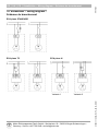
DE │ UK │ FR │ Schaltbilder – Wiring diagram – Schémas de branchement
Schaltbilder – Wiring diagram – 14.
Schémas de branchement
ECA piano STANDARD
ECA piano TC
ECA piano H
Variante 1 Variante 2
Maico Elektroapparate-Fabrik GmbH • Steinbeisstr. 20 • 78056 Villingen-Schwenningen •
08.16_Es
0185.1111.0003_RLF.3_08.16_DSW
-
 1
1
-
 2
2
-
 3
3
-
 4
4
-
 5
5
-
 6
6
-
 7
7
-
 8
8
-
 9
9
-
 10
10
-
 11
11
-
 12
12
-
 13
13
-
 14
14
-
 15
15
-
 16
16
-
 17
17
-
 18
18
-
 19
19
-
 20
20


Maico ECA piano STANDARD Mounting And Operating Instructions
- Typ
- Mounting And Operating Instructions
- Dieses Handbuch eignet sich auch für
in anderen Sprachen
- English: Maico ECA piano STANDARD
- français: Maico ECA piano STANDARD
Verwandte Artikel
-
Maico ECA piano STANDARD Mounting And Operating Instructions
-
-
-
-
-
-
-
-
-