
PORTEPORTE
PORTEPORTE
PORTE
AUTOMATICHEAUTOMATICHE
AUTOMATICHEAUTOMATICHE
AUTOMATICHE
| |
| |
|
AUTOMATIC DOORS
| |
| |
|
PORTESPORTES
PORTESPORTES
PORTES
AUTOMATIQUESAUTOMATIQUES
AUTOMATIQUESAUTOMATIQUES
AUTOMATIQUES
| |
| |
|
AUTOMATISCHE TÜREN
| |
| |
|
PUERTASPUERTAS
PUERTASPUERTAS
PUERTAS
AUTOMATICASAUTOMATICAS
AUTOMATICASAUTOMATICAS
AUTOMATICAS
SISTEMASISTEMA
SISTEMASISTEMA
SISTEMA
ANTIPANICOANTIPANICO
ANTIPANICOANTIPANICO
ANTIPANICO
ANTI-PANIC SYSTEM
SISTEMESISTEME
SISTEMESISTEME
SISTEME
ANTIPANIQUEANTIPANIQUE
ANTIPANIQUEANTIPANIQUE
ANTIPANIQUE
ANTIPANIK-SYSTEM
SISTEMASISTEMA
SISTEMASISTEMA
SISTEMA
ANTIPÁNICOANTIPÁNICO
ANTIPÁNICOANTIPÁNICO
ANTIPÁNICO
MA7032
CARACTERISTICAS TECNICASCARACTERISTICAS TECNICAS
CARACTERISTICAS TECNICASCARACTERISTICAS TECNICAS
CARACTERISTICAS TECNICAS
::
::
:
Dispositivo de apertura en caso deDispositivo de apertura en caso de
Dispositivo de apertura en caso deDispositivo de apertura en caso de
Dispositivo de apertura en caso de
falta de tensión de línea, con bateríasfalta de tensión de línea, con baterías
falta de tensión de línea, con bateríasfalta de tensión de línea, con baterías
falta de tensión de línea, con baterías
tampón (12+12V - 1,2Ah) paratampón (12+12V - 1,2Ah) para
tampón (12+12V - 1,2Ah) paratampón (12+12V - 1,2Ah) para
tampón (12+12V - 1,2Ah) para
automatismos CORSA/RODEO.automatismos CORSA/RODEO.
automatismos CORSA/RODEO.automatismos CORSA/RODEO.
automatismos CORSA/RODEO.
Efectua:Efectua:
Efectua:Efectua:
Efectua:
- selección de funciones dip-switch
ZP7/ZP8;
- sólo apertura 9-OFF; 10-ON;
- sólo cierre 9-ON; 10-ON;
- más maniobras 9-OFF; 10-OFF;
- Reset automático una vez
reactivada la tensión de línea;
- Conexión a encastre en ZP7/ZP8.
Instalación :Instalación :
Instalación :Instalación :
Instalación :
1) Antes de proceder, desconectar la
tensión al automatismo;
2) Conectar la tarjeta LBC en la ZP7 /
ZP8, poniendo atención a la correcta
introducción de la misma;
3) Montar el soporte y las correspon-
dientes baterías conectándolas a los
terminales de la tarjeta ZP7/ZP8;
4) Conectar el hilo puente (*) entre las
dos baterías;
5) Comprobar el funcionamiento del
sistema antipánico desconectando de
nuevo la tensión de línea.
NOTANOTA
NOTANOTA
NOTA: Si el automatismo está dotado
de selector de funciones MA7041,
comprobar que esté seleccionada la
función “Emergency” (led amarillo
encendido) que indica la habilitación
de la función ANTIPANICO.
Si no está conectado el selector
MA7041, hay que puentear los
contactos 1 y 3 (**) en la regleta de
bornes relativa. Esta operación es
obligatoria para habilitar el “sistema
antipánico”.
TECNISCHE DATENTECNISCHE DATEN
TECNISCHE DATENTECNISCHE DATEN
TECNISCHE DATEN
Steuersystem mit PufferbatterieSteuersystem mit Pufferbatterie
Steuersystem mit PufferbatterieSteuersystem mit Pufferbatterie
Steuersystem mit Pufferbatterie
(12+12V/1,2 Ah), zur Öffnung des(12+12V/1,2 Ah), zur Öffnung des
(12+12V/1,2 Ah), zur Öffnung des(12+12V/1,2 Ah), zur Öffnung des
(12+12V/1,2 Ah), zur Öffnung des
Tores bei Netzspannungsausfall; fürTores bei Netzspannungsausfall; für
Tores bei Netzspannungsausfall; fürTores bei Netzspannungsausfall; für
Tores bei Netzspannungsausfall; für
die Antriebssysteme CORSA / RODEOdie Antriebssysteme CORSA / RODEO
die Antriebssysteme CORSA / RODEOdie Antriebssysteme CORSA / RODEO
die Antriebssysteme CORSA / RODEO
Führt folgende Funktionen aus:Führt folgende Funktionen aus:
Führt folgende Funktionen aus:Führt folgende Funktionen aus:
Führt folgende Funktionen aus:
- funktionswahl dip-switch ZP7/ZP8;
- nur Öffnen 9-OFF; 10-ON;
- nur zulaufzeit 9-ON; 10-ON;
- mehrere Steuerungen 9-OFF; 10-OFF.
- Automatik-Reset bei vieder-
kehrender Netspannung;
- Steckverbindung auf ZP7/ZP8.
Installation :Installation :
Installation :Installation :
Installation :
1) Den Automatismus vor Ausführen
der entsprechenden Anschlüsse span-
nungsfrei schalten;
2) Das Steckmodul LBC auf ZP7/ZP8
aufstecken und dessen korrekten Sitz
überprüfen;
3) Den Batterienträger mit den
entsprechenden Batterien montieren
und die Batterien an die entsprechenden
Klemmen am Steckmodul ZP7/ZP8
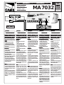
anschließen (siehe Abb.1);
4) Den zum Lieferumfang gehörenden
Brückendraht (*) erst nach erfolgter;
5) Die Netzspannung neuerlich
abtrennen und die einwandfreie
Funktion des Antipanik-Systems
überprüfen.
HINWEISHINWEIS
HINWEISHINWEIS
HINWEIS: Wenn das Antipanik-System
mit Funktionswahlschalter MA 7041
ausgestattet ist, überprüfen, ob sich
dieser in Stellung “Emergency” (gelbe
Led leuchtet auf), die die Ansteuerung
der ANTIPANIK-Funktion anzeigt,
befindet.
Sollte der Wählschalter MA7041 nicht
angeschlossen sein, achten Sie bitte
darauf, die Kontakte 1 und 3 an den
gleichnamigen Klemmen zu über-
brücken (**). Dieser Arbeitsschritte ist
notwendig, um das “Antipaniksystem”
zu aktivieren.
CARACTERISTIQUES TECHNIQUESCARACTERISTIQUES TECHNIQUES
CARACTERISTIQUES TECHNIQUESCARACTERISTIQUES TECHNIQUES
CARACTERISTIQUES TECHNIQUES
Dispositif d'ouverture en casDispositif d'ouverture en cas
Dispositif d'ouverture en casDispositif d'ouverture en cas
Dispositif d'ouverture en cas
d'absence de tension de ligne, avecd'absence de tension de ligne, avec
d'absence de tension de ligne, avecd'absence de tension de ligne, avec
d'absence de tension de ligne, avec
des batteries-tampons (12+12Vdes batteries-tampons (12+12V
des batteries-tampons (12+12Vdes batteries-tampons (12+12V
des batteries-tampons (12+12V
1,2Ah).1,2Ah).
1,2Ah).1,2Ah).
1,2Ah).
Il effectue :Il effectue :
Il effectue :Il effectue :
Il effectue :
- selection de fonctions dip-switch ZP7/8:
- uniquement l'ouverture 9 OFF; 10 ON;
- uniquement fermeture 9 ON; 10 ON;
- plusieurs manoeuvres 9 OFF; 10 OFF;
- Rearmement automatique au retour
de la tension de ligne;
- Connexion par brachment sur
ZP7/ZP8.
Installation :Installation :
Installation :Installation :
Installation :
1) Couper la tension à l’automatisme
avant d’effectuer l’installation;
2) Brancher la carte LBC sur la ZP7 /
ZP8 en veillant à l’introduire
correctement;
3) Monter le support et les batteries
correspondantes en les connectant aux
contacts de la carte ZP7/ZP8 (fig.1);
4) Introduir le fil de pont fournies avec
le materiel (*);
5) Vérifier maintenant que
l’antipanique fonctionne correctement
en coupant de nouveau la tension de
ligne.
NOTENOTE
NOTENOTE
NOTE: Si l’automatisme comprend le
sélecteur de fonctions MA7041, vérifier
que la fonction «Emergency» (led jaune
allumé), qui indique que la fonction
ANTIPANIQUE est autorisée, est
sélectionnée.
Si le sélecteur MA7041 s’est pas
connecté, s’assurer de mettre en pontet
les contacts 1 et 3 (**) sur les bornes
homonymes. Cette opération est
obligatoire pour habiliter le “système
antipanique”.
TECHNICAL SPECIFICATIONTECHNICAL SPECIFICATION
TECHNICAL SPECIFICATIONTECHNICAL SPECIFICATION
TECHNICAL SPECIFICATION
Emergency system equipped withEmergency system equipped with
Emergency system equipped withEmergency system equipped with
Emergency system equipped with
backup batteries (12+12V - 1,2Ah)backup batteries (12+12V - 1,2Ah)
backup batteries (12+12V - 1,2Ah)backup batteries (12+12V - 1,2Ah)
backup batteries (12+12V - 1,2Ah)
for opening CORSA/RODEOfor opening CORSA/RODEO
for opening CORSA/RODEOfor opening CORSA/RODEO
for opening CORSA/RODEO
automations systems in case ofautomations systems in case of
automations systems in case ofautomations systems in case of
automations systems in case of
power failure.power failure.
power failure.power failure.
power failure.
Performs :Performs :
Performs :Performs :
Performs :
- function selection dip-switch
ZP7/ZP8:
- opening only 9-OFF; 10-ON;
- closing only 9-ON; 10 ON;
- multiple man. 9-OFF; 10-OFF;
- Automatically reset when line voltage
is restored;
- Plug-in connection on ZP7/ZP8.
Installation:Installation:
Installation:Installation:
Installation:
1) Shut off the power to the auto-
mation system before proceeding;
2) Plug card LBC into ZP7/ZP8. Be sure
to insert the card correctly;
3) Install the battery support and
batteries, and connect the batteries to
the terminals on card ZP7/ZP8 (fig. 1);
4) Insert the point supplied with the
unit (*), following indications on fig.1;
5) Now, check the emergency system
for proper operation by shutting off the
power once again.
NOTENOTE
NOTENOTE
NOTE: If the automation system is
equipped with function selector
MA7041, make sure that the
“Emergency” function has been selected
on the selector (yellow LED lit), which
indicates that the EMERGENCY function
has been activated.
If the MA7041 selector is not con-
nected, be sure to bond* contacts 1 and
3 (**) on the terminal board of the
same name. This operation is obliga-
tory in order to enable the “anti-panic
system”.
CARATTERISTICHE TECNICHECARATTERISTICHE TECNICHE
CARATTERISTICHE TECNICHECARATTERISTICHE TECNICHE
CARATTERISTICHE TECNICHE
Dispositivo di apertura in caso diDispositivo di apertura in caso di
Dispositivo di apertura in caso diDispositivo di apertura in caso di
Dispositivo di apertura in caso di
mancanza di tensione di linea, conmancanza di tensione di linea, con
mancanza di tensione di linea, conmancanza di tensione di linea, con
mancanza di tensione di linea, con
batterie tampone (12+12V 1,2Ah)batterie tampone (12+12V 1,2Ah)
batterie tampone (12+12V 1,2Ah)batterie tampone (12+12V 1,2Ah)
batterie tampone (12+12V 1,2Ah)
per automatismi CORSA/RODEOper automatismi CORSA/RODEO
per automatismi CORSA/RODEOper automatismi CORSA/RODEO
per automatismi CORSA/RODEO.
Selezionando le seguenti funzioni sui
dip-switch (a 10 vie) del quadro ZP7/8
esegueesegue
esegueesegue
esegue:
- sola apertura (9-OFF; 10-ON);
- sola chiusura (9-ON; 10-ON);
- manovre totali (9-OFF; 10-OFF).
Reset automatico al ripristino della ten-
sione di linea.
Connessione ad innesto su ZP7/ZP8.
Installazione:Installazione:
Installazione:Installazione:
Installazione:
1)Togliere tensione all’automazione
prima di procedere;
2)Innestare la scheda LBC sul quadro
ZP7/ZP8 facendo attenzione al corretto
inserimento della stessa;
3)Montare il supporto e le relative
batterie collegandole ai terminali del
quadro ZP7/8 come da figura1;
4)Inserire il filo-ponte in dotazione (*);
5)Togliere la tensione di linea e verifi-
care l'espletamento della manovra di
antipanico selezionato.
NOTANOTA
NOTANOTA
NOTA: Se l'automazione è completa
del selettore funzioni MA7041, verifi-
care che sia selezionata la funzione
"emergency", (LED giallo acceso) che
indica l'abilitazione della funzione
"antipanico".
Nel caso non sia collegato il selettore
MA7041, assicurarsi di ponticellare i
contatti 1 e 3 (**) sull'omonima
morsettiera. Questa operazione è ob-
bligatoria per abilitare il "sistema
antipanico".
DocumentazioneDocumentazione
DocumentazioneDocumentazione
Documentazione
TecnicaTecnica
TecnicaTecnica
Tecnica
M72M72
M72M72
M72
rev. rev.
rev. rev.
rev.
1.21.2
1.21.2
1.2
©©
©©
©
CAME 04/98 CAME 04/98
CAME 04/98 CAME 04/98
CAME 04/98
119PM72
1234567
MF9011 - MF9111 MA7032
12345678
MA7041
V.RALL.CH V/CH V/AP P.R.CH FRENO V.RALL.AP.
FUSIBILE
ACCESSORI
1,6A
M
N
E
+
S
S
E
-
-
BATT.
+
24A
24A
BATTERY
-
+
LBC
(**)
+
_
+
_
(*)
12V - 1,2Ah
12V - 1,2Ah
FIG.-ADD. 1FIG.-ADD. 1
FIG.-ADD. 1FIG.-ADD. 1
FIG.-ADD. 1
ITALIANOITALIANO
ITALIANOITALIANO
ITALIANO
DEUTSCHDEUTSCH
DEUTSCHDEUTSCH
DEUTSCH
ESPANOLESPANOL
ESPANOLESPANOL
ESPANOL
ENGLISHENGLISH
ENGLISHENGLISH
ENGLISH
FRANÇAISFRANÇAIS
FRANÇAISFRANÇAIS
FRANÇAIS
-
 1
1

in anderen Sprachen
- English: CAME MA7032 Owner's manual
- français: CAME MA7032 Le manuel du propriétaire
- español: CAME MA7032 El manual del propietario
- italiano: CAME MA7032 Manuale del proprietario
Verwandte Artikel
-
CAME MA7034 Bedienungsanleitung
-
-
-
-
-
-
-
-
-