
ELECTRIC COOKTOPS
INSTALLATION INSTRUCTIONS
INSTRUCCIONES DE INSTALACIÓN
INSTRUCTIONS D’INSTALLATION
ISTRUZIONI PER L’INSTALLAZIONE
INSTALLATIONSANWEISUNGEN


3
ENGLISH 4
ESPÃNOL 22
FRANÇAIS 40
ITALIANO 58
DEUTSCH 76

As you follow these instruc tions, you will
notice WARNING and CAUTION symbols.
This blocked information is impor tant for the
safe and efficient installation of Wolf equip-
ment. There are two types of potential
hazards that may occur during installation.
Another footnote we would like to identify is
IMPORTANT NOTE: This highlights informa-
tion that is especially relevant to a problem-
free installation.
signals a situation where minor injury or
product damage may occur if you do not
follow instructions.
states a hazard that may cause serious
injury or death if precautions are not
followed.
WOLF
®
is a registered trademark of Wolf Appliance, Inc.
CONTACT
INFORMATION
Website:
wolfappliance.com

5
WOLF ELECTRIC COOKTOPS
BEFORE YOU START
Proper installation is your responsibility.
Have a qualified technician install this
cooktop. You must also assure that electri-
cal installation is adequate and in compli-
ance with all local codes and ordinances.
Installations and repairs must be performed
by a qualified or licensed contractor or
electrician qualified or licensed by the state,
province, or region where this appliance is
being installed.
Make sure you have everything necessary
for correct installation. It is the responsibil-
ity of the installer to comply with the
installation clearances specified in this book
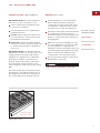
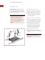
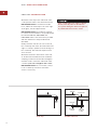
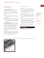
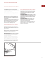
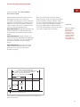
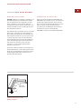
and on the product rating plate. The rating
plate is located on the underside of the
cooktop. Refer to the illustration below.
Electrical ground is required; see Electrical
Requirements on page 16.
This cooktop is intended for indoor use.
INSTALLATION REQUIREMENTS
IMPORTANT NOTE:
Save these Installation
Instructions for the local inspector’s use.
Please read the entire Installation Instruc-
tions prior to installation.
This installation must be completed by a
qualified technician.
Installer:
please retain these instructions
for local inspector’s reference, then leave
them with the homeowner.
Homeowner:
please read and keep these
instructions for future reference and be sure
to read the entire Use & Care Information
prior to use.
IMPORTANT NOTE:
This appliance must be
installed in accordance local codes. The correct
voltage, frequency and amperage must be
supplied to the appliance from a dedicated,
grounded circuit which is protected by a
properly sized circuit breaker or time delay
fuse. The proper voltage, frequency, and
power ratings are listed on the product rating
plate.
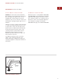
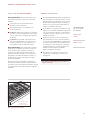
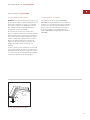
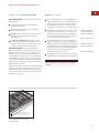
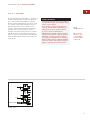
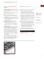
Record the model and serial numbers before
installing the cooktop. Both numbers are on
the rating plate, located on the underside of
the cooktop. Refer to the illustration below.
RATING PLATE
INFORMATION
Model Number
Serial Number
Rating plate location
Location of rating
plate under cooktop

6
WOLF ELECTRIC COOKTOPS
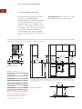
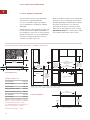
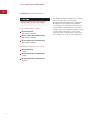
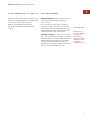
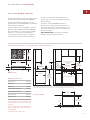
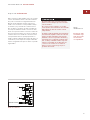
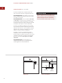
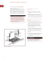
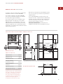
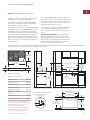
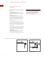
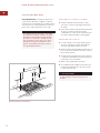
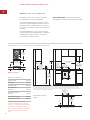
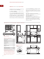
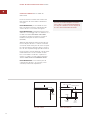
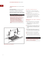
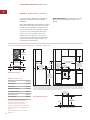
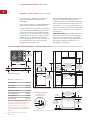
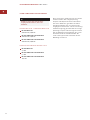
LOCATION IN COUNTERTOP
A)
Minimum flat countertop surface. Must be
equal to or greater than cooktop width.
B)
Minimum 25 mm wide clearance from the
cooktop side edge to any combustible
surface up to 457 mm above the cooktop
(noted by shaded area).
OVERHEAD CABINET DIMENSIONS
C)
Minimum spacing between overhead side
cabinets must be greater than or equal to
the nominal width of the cooktop unit(s).
D)
Minimum 457 mm vertical distance from
the countertop to the bottom of side
cabinets within minimum side clearance.
E)
Minimum vertical distance between the
countertop and combustible materials
above the cooktop must be 762 mm.
F)
Minimum 25 mm from rear wall.
G)
Maximum 330 mm depth of overhead and
side cabinets directly above and within side
clearance.
Failure to locate the cooktop unit
without the proper clearances will result
in a fire hazard.
C
G
D
A
B
B
E
F
Minimum clearances for installation
SITE PREPARATION
IMPORTANT NOTE:
Installation of the Wolf
electric cooktop must meet the following
location requirements. All dimensions listed
are minimum requirements for safe operation.
Refer to the illustration below.
To eliminate the risk of burns or fire by
reaching over heated surface units,
cabinet storage space located above the
surface units should be avoided. If
cabinet storage is to be provided, the risk
can be reduced by installing a ventilation
hood that projects horizontally a
minimum of 127 mm beyond the bottom
cabinets.

7
INSTALLATION INSTRUCTIONS
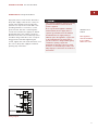
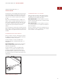
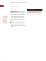
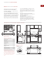
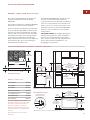
INSTALLATION SPECIFICATIONS
The illustrations on pages 8–13 provide the
overall dimensions, installation specifications
and countertop cut-out for each of the Wolf
electric cooktop models.
These cooktops are designed to fit a standard
610 mm deep base cabinet with a 635 mm
deep countertop. Before making the counter-
top cut-out, verify that the cooktop will clear
the side walls of the base cabinet below.
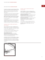
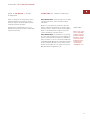
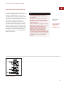
Clearance is required for the terminal block
and conduit located at the right rear of the
cooktop. Refer to the illustration below for
dimensions.
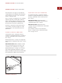
FRAMED ELECTRIC COOKTOPS
For framed models, a minimum 146 mm
clearance is required between the countertop
and any combustible surface directly below
the cooktop.
Wolf framed electric cooktops are designed to
be installed in combination with other cooktop
units.
IMPORTANT NOTE:
When multiple cooktop
units are installed side by side, refer to the
countertop cut-out dimensions on page 11.
Wolf framed electric cooktops can accommo-
date a Wolf downdraft ventilation system.
Refer to installation instructions provided with
the downdraft for additional specifications.
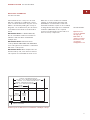
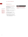
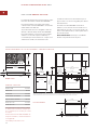
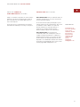
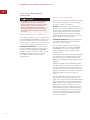
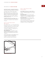
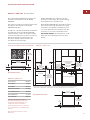
56 mm
84 mm
24 mm
22 mm
32 mm
Terminal block dimensions
UNFRAMED ELECTRIC COOKTOPS
For unframed models, a minimum 159 mm
clearance is required between the countertop
and any combustible surface directly below
the cooktop.
IMPORTANT NOTE:
Unframed electric
cooktops are not designed to be installed in
combination with other cooktops.
IMPORTANT NOTE:
Unframed electric
cooktops cannot be installed with a downdraft
ventilation system.
For installation options of the unframed
electric cooktops, refer to Unframed Installa-
tions on pages 14–15.

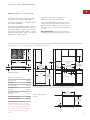
8
E
102 mm
381 mm
381
mm
51 mm*
min
CUT-OUT TO
COMBUSTIBLE
MATERIALS
(BOTH SIDES)
340 mm
COOKTOP CUT-OUT
WIDTH
340 mm
COOKTOP CUT-OUT
WIDTH
838 mm
RECOMMENDED
CABINET WIDTH
457 mm
NOTE: Application shown allows for installation of two 381 mm modules side-by-side with 838 mm recommended cabinet width. 457 mm
recommended cabinet width for installation of single 381 mm cooktop or module. *Minimum clearance from both side edges of cooktop cut-out
to combustible materials up to 457 mm above countertop. **Minimum clearance from rear edge of cooktop cut-out to combustible materials up
to 457 mm above countertop.
489 mm
COOKTOP CUT-OUT
DEPTH
64 mm
min
914 mm
STANDARD
FLOOR TO
COUNTERTOP
HEIGHT
330 mm
max
762 mm
COUNTERTOP TO
COMBUSTIBLE
MATERIALS
ABOVE COOKTOP
FRONT OF COUNTERTOP
64 mm
min
489 mm
COOKTOP
CUT-OUT DEPTH
51**
mm
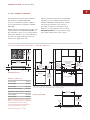
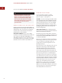
Overall Dimensions
Countertop Cut-Out
533 mm
OVERALL
DEPTH
381 mm
OVERALL WIDTH
127 mm
96 mm
TERMINAL BOX
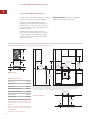
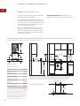
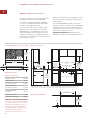
MODEL ICBCT15E
Overall Width 381 mm
Overall Height 96 mm
Overall Depth 533 mm
Minimum Cabinet Depth 578 mm
Minimum Height Clearance*
102 mm
Cut-Out Width 340 mm
Cut-Out Depth 489 mm
INSTALLATION SPECIFICATIONS – MODEL ICBCT15E
FRAMED MODEL ICBCT15E
The illustrations below provide installation
specifications for Model ICBCT15E.
If Model ICBCT15E is installed above cabinets,
the electrical placement is not critical. A
grounded electrical box should be located
within 1.2 m of the right rear of the cooktop.
For installation above an oven, unless you are
using cabinets deeper than 610 mm, it is
recommended that the electrical supply be
placed in the base cabinet to the right of the
oven.
WOLF
ELECTRIC COOKTOPS
IMPORTANT NOTE:
Do not block the cooling
fan located at the bottom of the cooktop.
*Minimum 146 mm clearance is required
between countertop and any combustible
surface directly below the cooktop.
For detailed terminal block dimensions,
refer to the illustration on page 7.
Dimensions may vary to
±
3 mm.

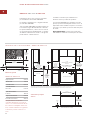
9
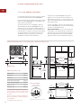
51 mm*min
CUT-OUT TO
COMBUSTIBLE
MATERIALS
(BOTH SIDES)
457 mm
489 mm
COOKTOP CUT-OUT
DEPTH
64 mm
min
914 mm
STANDARD
FLOOR TO
COUNTERTOP
HEIGHT
330 mm
max
762 mm
COUNTERTOP TO
COMBUSTIBLE
MATERIALS
ABOVE COOKTOP
610 mm min
*Minimum clearance from both side edges of cooktop cut-out to combustible materials up to 457 mm above countertop. **Minimum clearance
from rear edge of cooktop cut-out to combustible materials up to 457 mm above countertop.
102 mm
254
mm
89 mm
95 mm
min
762 mm OVEN OPENING
E
721 mm COOKTOP
CUT-OUT WIDTH
721 mm
COOKTOP CUT-OUT WIDTH
FRONT OF COUNTERTOP
64 mm
min
489 mm
COOKTOP
CUT-OUT DEPTH
838 mm
RECOMMENDED
CABINET WIDTH
762 mm min
51**
mm
Overall Dimensions
Countertop Cut-Out
533 mm
OVERALL
DEPTH
762 mm
OVERALL WIDTH
127 mm
96 mm
TERMINAL BOX
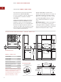
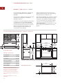
FRAMED MODEL ICBCT30E
The illustrations below provide installation
specifications for Model ICBCT30E.
For ease of installation, 838 mm cabinets
are recommended for installation of Model
ICBCT30E.
A Wolf 762 mm or 914 mm built-in single oven
may be installed below Model ICBCT30E. For
this installation, unless you are using cabinets
deeper than 610 mm, it is recommended that
the electrical supply be placed in the base
cabinet to the right of the oven.
Refer to installation instructions provided with
the built-in oven for additional specifications.
If Model ICBCT30E is installed above cabinets,
the electrical placement is not critical. A
grounded electrical box should be located
within 1.2 m of the right rear of the cooktop.
IMPORTANT NOTE:
Do not block the cooling
fan located at the bottom of the cooktop.
MODEL ICBCT30E
Overall Width 762 mm
Overall Height 96 mm
Overall Depth 533 mm
Minimum Cabinet Depth 578 mm
Minimum Height Clearance*
102 mm
Cut-Out Width 721 mm
Cut-Out Depth 489 mm
INSTALLATION SPECIFICATIONS – MODEL ICBCT30E
INSTALLATION
INSTRUCTIONS
*Minimum 146 mm clearance is required
between countertop and any combustible
surface directly below the cooktop.
For detailed terminal block dimensions,
refer to the illustration on page 7.
Dimensions may vary to
±
3 mm.

10
WOLF ELECTRIC COOKTOPS
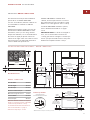
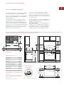
FRAMED MODEL ICBCT36E
The illustrations below provide installation
specifications for Model ICBCT36E.
For ease of installation, 991 mm cabinets
are recommended for installation of Model
ICBCT36E.
A Wolf 762 mm or 914 mm built-in single oven
may be installed below Model ICBCT36E. For
this installation, unless you are using cabinets
deeper than 610 mm, it is recommended that
the electrical supply be placed in the base
cabinet to the right of the oven.
Refer to installation instructions provided with
the built-in oven for additional specifications.
If Model ICBCT36E is installed above cabinets,
the electrical placement is not critical. A
grounded electrical box should be located
within 1.2 m of the right rear of the cooktop.
IMPORTANT NOTE:
Do not block the cooling
fan located at the bottom of the cooktop.
51 mm*min
CUT-OUT TO
COMBUSTIBLE
MATERIALS
(BOTH SIDES)
457 mm
489 mm
COOKTOP CUT-OUT
DEPTH
64 mm
min
914 mm
STANDARD
FLOOR TO
COUNTERTOP
HEIGHT
330 mm
max
762 mm
COUNTERTOP TO
COMBUSTIBLE
MATERIALS
ABOVE COOKTOP
610 mm min
*Minimum clearance from both side edges of cooktop cut-out to combustible materials up to 457 mm above countertop. **Minimum clearance from
rear edge of cooktop cut-out to combustible materials up to 457 mm above countertop.
873 mm
COOKTOP CUT-OUT WIDTH
873 mm
COOKTOP CUT-OUT WIDTH
991 mm
RECOMMENDED CABINET WIDTH
914 mm min
102 mm
254
mm
89 mm
914 mm OVEN OPENING
95 mm
min
E
64 mm
min
FRONT OF COUNTERTOP
489 mm
COOKTOP
CUT-OUT DEPTH
51**
mm
Overall Dimensions
Countertop Cut-Out
533 mm
OVERALL
DEPTH
914 mm
OVERALL WIDTH
127 mm
96 mm
TERMINAL BOX
MODEL ICBCT36E
Overall Width 914 mm
Overall Height 96 mm
Overall Depth 533 mm
Minimum Cabinet Depth 578 mm
Minimum Height Clearance*
102 mm
Cut-Out Width 873 mm
Cut-Out Depth 489 mm
INSTALLATION SPECIFICATIONS – MODEL ICBCT36E
*Minimum 146 mm clearance is required
between countertop and any combustible
surface directly below the cooktop.
For detailed terminal block dimensions,
refer to the illustration on page 7.
Dimensions may vary to
±
3 mm.

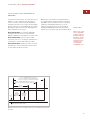
11
INSTALLATION INSTRUCTIONS
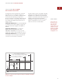
MULTIPLE COOKTOP
INSTALLATION
If the framed electric cooktop is to be used
with any combination of additional cooktop
units or modules with a filler strip, the cut-out
width is calculated by adding the correspon-
ding units' cut-out dimensions plus 32 mm for
each additional unit. Refer to the illustration
below.
IMPORTANT NOTE:
For Model ICBCT15E,
the cut-out width should be increased from
340 mm to 356 mm when installed with
multiple units.
IMPORTANT NOTE:
Unframed electric
cooktops Models ICBCT30EU and ICBCT36EU
are not designed to be installed in combination
with other cooktop units.
IMPORTANT NOTE:
When multiple units are
installed side by side, each unit must have its
own separate recommended electrical circuit.
64 mm
min
FRONT OF COUNTERTOP
489 mm
CUT-OUT
DEPTH
743 mm
TWO MODULES WIDTH
1130 mm – THREE MODULES WIDTH OR
1124 mm – 762 mm COOKTOP AND ONE MODULE
1518 mm – FOUR MODULES WIDTH OR
1511 mm – 762 mm COOKTOP AND TWO MODULES OR
1276 mm – 914 mm COOKTOP AND ONE MODULE
356 mm
CUT-OUT
WIDTH
Countertop cut-out dimensions for installation of multiple cooktops
ACCESSORIES
Optional acces-
sories are available
through your
Wolf dealer. To
obtain local dealer
information, visit
our website,
wolfappliance.com.
When two or more modules are installed
together, an integrated module filler strip
(IFILLER/S) is recommended. If a 762 mm
downdraft ventilation system is also installed,
an integrated module support for downdraft
ventilation (ISUPPORT) is also required.
Contact your Wolf dealer for information on
these accessory components.

12
51 mm*min
CUT-OUT TO
COMBUSTIBLE
MATERIALS
(BOTH SIDES)
457 mm
914 mm
STANDARD
FLOOR TO
COUNTERTOP
HEIGHT
762 mm
COUNTERTOP TO
COMBUSTIBLE
MATERIALS
ABOVE COOKTOP
762 mm OVEN OPENING
838 mm
RECOMMENDED
CABINET WIDTH
762 mm min
721 mm COOKTOP
CUT-OUT WIDTH
33 mm
RADIUS
62 mm
492 mm
COOKTOP
CUT-OUT DEPTH
11 mm RADIUS
765 mm**
RECESSED AREA FOR
FLUSH MOUNT INSTALLATION ONLY
FRONT OF COUNTERTOP
40 mm
537 mm**
RECESSED AREA
FOR FLUSH MOUNT
INSTALLATION ONLY
**Minimum dimension, but may be exceeded by up to 3 mm.
RECESSED AREA FOR
FLUSH MOUNT INSTALLATION ONLY
8 mm
22 mm
max
COUNTERTOP
PROFILE
330 mm
max
610 mm min
102 mm min
SEE COUNTERTOP
CUT-OUT BELOW
SEE COUNTERTOP
CUT-OUT BELOW
*Minimum clearance from both side edges and back edge of cooktop cut-out to combustible materials up to 457 mm above countertop.
51 mm*
E
254
mm
102 mm
min
TO OVEN
OPENING
89 mm
114 mm
Overall Dimensions
Countertop Cut-Out
533 mm
OVERALL
DEPTH
762 mm
OVERALL WIDTH
140 mm
108 mm
TERMINAL BOX
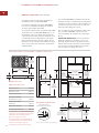
UNFRAMED MODEL ICBCT30EU
The illustrations below provide installation
specifications for Model ICBCT30EU.
For ease of installation, 838 mm cabinets are
recommended for installation of Model
ICBCT30EU.
A Wolf 762 mm built-in single oven may be
installed below Model ICBCT30EU. For this
installation, unless you are using cabinets
deeper than 610 mm, it is recommended that
the electrical supply be placed in the base
cabinet to the right of the oven. Refer to instal-
lation instructions provided with the built-in
oven for additional specifications.
If Model ICBCT30EU is installed above
cabinets, electrical placement is not critical. A
grounded electrical box should be located
within 1.2 m of the right rear of the cooktop.
For Model ICBCT30EU installation options,
refer to Unframed Installations on pages
14–15.
IMPORTANT NOTE:
For flush mount applica-
tions, it is recommended to measure the
cooktop glass before cutting the countertop to
ensure a proper fit. Small variances may exist
between the template and the cooktop.
MODEL ICBCT30EU
Overall Width 762 mm
Overall Height 108 mm
Overall Depth 533 mm
Minimum Cabinet Depth 578 mm
Minimum Height Clearance*
114 mm
Cut-Out Width 721 mm
Cut-Out Depth 492 mm
INSTALLATION SPECIFICATIONS – MODEL ICBCT30EU
WOLF ELECTRIC COOKTOPS
*Minimum 159 mm clearance is required
between countertop and any combustible
surface directly below the cooktop.
For detailed terminal block dimensions,
refer to the illustration on page 7.
Dimensions may vary to
±
3 mm.

13
INSTALLATION INSTRUCTIONS
UNFRAMED MODEL ICBCT36EU
The illustrations below provide installation
specifications for Model ICBCT36EU.
For ease of installation, 991 mm cabinets are
recommended for installation of Model
ICBCT36EU.
A Wolf 914 mm built-in single oven may be
installed below Model ICBCT36EU. For this
installation, unless you are using cabinets
deeper than 610 mm, it is recommended that
the electrical supply be placed in the base
cabinet to the right of the oven. Refer to instal-
lation instructions provided with the built-in
oven for additional specifications.
If Model ICBCT36EU is installed above
cabinets, electrical placement is not critical.
A grounded electrical box should be located
within 1.2 m of the right rear of the cooktop.
For Model ICBCT36EU installation options,
refer to Unframed Installations on pages
14–15.
IMPORTANT NOTE:
For flush mount applica-
tions, it is recommended to measure the
cooktop glass before cutting the countertop to
ensure a proper fit. Small variances may exist
between the template and the cooktop.
51 mm*min
CUT-OUT TO
COMBUSTIBLE
MATERIALS
(BOTH SIDES)
457 mm
914 mm
STANDARD
FLOOR TO
COUNTERTOP
HEIGHT
762 mm
COUNTERTOP TO
COMBUSTIBLE
MATERIALS
ABOVE COOKTOP
*Minimum clearance from both side edges and back edge of cooktop cut-out to combustible materials up to 457 mm above countertop.
991 mm
RECOMMENDED CABINET WIDTH
914 mm min
914 mm OVEN OPENING
918 mm**
RECESSED AREA FOR
FLUSH MOUNT INSTALLATION ONLY
873 mm
COOKTOP CUT-OUT WIDTH
33 mm
RADIUS
FRONT OF COUNTERTOP
62 mm
492 mm
COOKTOP
CUT-OUT DEPTH
40 mm
537 mm**
RECESSED AREA
FOR FLUSH MOUNT
INSTALLATION ONLY
11 mm RADIUS
**Minimum dimension, but may be exceeded by up to 3 mm.
RECESSED AREA FOR
FLUSH MOUNT INSTALLATION ONLY
8 mm
22 mm
max
COUNTERTOP
PROFILE
SEE COUNTERTOP
CUT-OUT BELOW
330 mm
max
610 mm min
SEE COUNTERTOP
CUT-OUT BELOW
51 mm*
102 mm
min
E
254
mm
102 mm
min
TO OVEN
OPENING
89 mm
114 mm
Overall Dimensions
Countertop Cut-Out
533 mm
OVERALL
DEPTH
914 mm
OVERALL WIDTH
140 mm
108 mm
TERMINAL BOX
MODEL ICBCT36EU
Overall Width 914 mm
Overall Height 108 mm
Overall Depth 533 mm
Minimum Cabinet Depth 578 mm
Minimum Height Clearance*
114 mm
Cut-Out Width 873 mm
Cut-Out Depth 492 mm
INSTALLATION SPECIFICATIONS – MODEL ICBCT36EU
*Minimum 159 mm clearance is required
between countertop and any combustible
surface directly below the cooktop.
For detailed terminal block dimensions,
refer to the illustration on page 7.
Dimensions may vary to
±
3 mm.

14
WOLF ELECTRIC COOKTOPS
UNFRAMED INSTALLATIONS
MODELS ICBCT30EU AND ICBCT36EU
Unframed electric cooktop Models ICBCT30EU
and ICBCT36EU can be mounted flush with the
top of the countertop or as a frameless instal-
lation with the glass mounted on top of the
countertop surface.
IMPORTANT NOTE:
The materials required
for a flush mount installation are provided with
the unframed Models ICBCT30EU and
ICBCT36EU. Refer to the instructions provided
with the unframed cooktop installation kit
(#811358) for additional specifications.
FLUSH MOUNT INSTALLATION
There are two options for a flush mount
installation of the unframed electric cooktop;
Option 1 and Option 2.
OPTION 1:
For this flush mount installation, a
recessed area surrounding the standard coun-
tertop cut-out is required. Fabrication of the
recessed area must take place before the final
countertop installation. A template of the coun-
tertop cut-out is provided with the unframed
cooktop for fabrication purposes.
IMPORTANT NOTE:
This fabrication method is
not recommended for molded backsplash style
countertops (triple cove).
For countertop cut-out dimensions, refer to
the Installation Specifications illustration on
page 12 for Model ICBCT30EU and page 13 for
Model ICBCT36EU.
In order to rout the required recessed area for
this flush mount installation, a second
template must be made from 13 mm plywood.
The template will be used as a guide for a top
bearing router bit.
Make the wood template wide enough so that
clamps used to hold this template to the coun-
tertop do not interfere with the router base.
The cut-out dimension of the wood template
should match the outer perimeter of the
template supplied with the cooktop.
Center the wood template over the existing
cut-out in the countertop and clamp. It may be
helpful to use medium-strength double-sided
tape to adhere the template to the countertop;
this will keep the template from shifting during
the routing operation. Make sure that the
adhesive can be easily removed by testing it
on a scrap piece of the countertop. Using a top
bearing router bit with the wood template as a
guide, rout out a 8 mm deep recessed area in
the countertop cut-out.
Flush mount installations are intended
for granite, solid surface or stone coun-
tertop surfaces only. Failure to use high
heat resistant surface will result in coun-
tertop damage if hot cooking utensils are
accidentally moved off the cooking
surface.

15
INSTALLATION INSTRUCTIONS
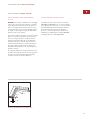
FRAMELESS INSTALLATION
Unframed electric cooktop Models ICBCT30EU
and ICBCT36EU can be installed as a frameless
application, with the glass mounted on top of
the countertop surface. For countertop cut-out
dimensions, refer to the Installation Specifica-
tions illustration on page 12 for Model
ICBCT30EU and page 13 for Model ICBCT36EU.
UNFRAMED INSTALLATIONS
FLUSH MOUNT INSTALLATION
OPTION 2:
For this flush mount installation,
the countertop cut-out will be the same size as
the outer edge of the glass top. It is recom-
mended that cooktop itself be used as the
template for the cut-out. Turn the cooktop over
and mark the opening using the glass top as a
template.
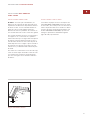
It will be necessary to attach L-shaped brackets
or cleats to the inner perimeter of the cut-out
to support the cooktop. The top edge of the
bracket can be no wider than 22 mm and will
be attached 8 mm below the surface of the
countertop. Refer to the illustration below.
Attachment of the brackets is up to the
installer's discretion, wherever enough coun-
tertop material is present.
For additional support in the cut-out area,
adhere scrap countertop material to the
bottom side of the countertop. Consult your
countertop supplier for the proper methods of
attachment.
22 mm
8 mm
L-Shaped
Brackets
Flush mount installation brackets

16
WOLF ELECTRIC COOKTOPS
ELECTRICAL REQUIREMENTS
REQUIRED POWER SUPPLY
Model ICBCT15E
220-240 V AC, 50/60 Hz
Models ICBCT30E and ICBCT30EU
220-240 V AC, 50/60 Hz
Models ICBCT36E and ICBCT36EU
220-240 V AC, 50/60 Hz
MAXIMUM CONNECTED LOAD
Model ICBCT15E
3.7 kW
Models ICBCT30E and ICBCT30EU
8.1 kW
Models ICBCT36E and ICBCT36EU
10.5 kW
Verify that power is disconnected from
the electrical box before proceeding.
This appliance must be installed in accordance
with local codes. The correct voltage,
frequency and amperage must be supplied to
the appliance from a dedicated, grounded
circuit which is protected by a properly sized
circuit breaker or time delay fuse. The proper
voltage, frequency and power ratings are listed
on the product rating plate, located on the
underside of the cooktop. Refer to the illustra-
tion on page 5 for location of the rating plate.

17
INSTALLATION INSTRUCTIONS
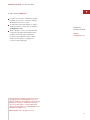
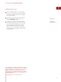
ELECTRICAL REQUIREMENTS
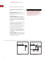
A properly rated cord should be attached to
the power supply of the electric cooktop as
shown in the illustration below. Open the
power box to expose the screws with corre-
sponding numbers. Loosen the 1, 5, and
ground screws. Run the cord through the
circular hole and into the supply box. Attach
the Neutral wire to the number 1 position.
Attach the line wire to the number 5 position
and attach the ground wire to the correspon-
ding ground screw. After tightening the
screws, tighten the cord strain relief then close
the cover to the power supply box without
pinching any of the wires.
The complete appliance must be properly
grounded at all times when electrical
power is applied.
Do not ground the appliance with the
neutral (white) house supply wire. A
separate ground wire must be utilized.
If aluminum house supply wiring is
utilized, splice the appliance copper wire
to the aluminum house wiring using
special connectors designed and agency
certified for joining copper and
aluminum. Follow the connector manu-
facturer's recommended procedure care-
fully. Improper connection can result in a
fire hazard!
IMPORTANT
NOTE
This appliance
must be installed
in accordance
with local codes.
GROUND
L1
N
Wiring diagram

18
COOKTOP INSTALLATION
Attach the foam strip to the underside of the
cooktop frame. Refer to the illustration below.
IMPORTANT NOTE:
For frameless installa-
tions, adhere the foam strip to the outer edge
of the glass, not the support frame.
IMPORTANT NOTE:
The materials required
for a flush mount installation are provided with
the unframed Models ICBCT30EU and
ICBCT36EU. Refer to the instructions provided
with the unframed cooktop installation kit
(#811358).
Gently lower the unit into the cut-out area in
the countertop and center. Check that the front
edge of cooktop is parallel to the front edge of
the countertop. Check that all required clear-
ances are met.
Attach the brackets to the bottom of the unit,
as shown in the illustration below. Install the
clamping screws into the bracket and tighten
until the screws contact the underside of the
countertop.
Do not overtighten the screws.
IMPORTANT NOTE:
Do not seal the cooktop
to the countertop. It must be removed if
service is necessary.
COOKTOP
FOAM
STRIP
COOKTOP
COUNTERTOP
BRACKET
SCREWS
BRACKET
102 mm
CLAMPING
SCREW
Foam strip Installation brackets
If the ceramic glass top of the cooktop is
broken, turn off power to the unit. Do
not operate until glass has been replaced
by a Wolf authorized service center.
WOLF ELECTRIC COOKTOPS

19
BEFORE OPERATING THE COOKTOP
Clean the ceramic glass surface carefully using
the Cooktop Cleaning Crème provided with the
cooktop. Remove all cleaning residue.
Read the entire Wolf Electric Cooktops
Use & Care Information included with the
cooktop.
COOKTOP
REMOVAL
IMPORTANT NOTE:
This procedure should
only be performed by a Wolf authorized
service center.
If it is necessary to remove the cooktop for
cleaning or service, disconnect the electrical
supply. Remove the mounting brackets on the
right and left side of the unit and remove the
cooktop. Reinstall in the reverse order.
IMPORTANT NOTE:
For flush mount installa-
tions, use a razor blade to carefully cut around
the RTV perimeter seal. A new RTV installation
kit (#811358) will be required to reinstall the
cooktop. This kit is available through your
Wolf dealer. To obtain local dealer information,
visit our website, wolfappliance.com.
INSTALLATION INSTRUCTIONS
ACCESSORIES
Optional acces-
sories are available
through your
Wolf dealer. To
obtain local dealer
information, visit
our website,
wolfappliance.com.

20
This cooktop must be repaired only by a
Wolf authorized service center. The unit
must be disconnected from power prior
to service.
WOLF ELECTRIC COOKTOPS
TROUBLESHOOTING
IF COOKTOP DOES NOT OPERATE
IMPORTANT NOTE:
If the electric cooktop
does not operate properly, follow these
troubleshooting steps:
Verify that power is being supplied to the
cooktop.
Check electrical connections to ensure that
the installation has been completed
correctly.
Follow troubleshooting procedures as
described in the Wolf Electric Cooktops
Use & Care Information.
If the cooktop still does not work, contact
a Wolf authorized service center. Do not
attempt to repair the cooktop yourself.
Wolf is not responsible for service required
to correct a faulty installation.
ACCESSORIES
Optional acces-
sories are available
through your
Wolf dealer. To
obtain local dealer
information, visit
our website,
wolfappliance.com.
Seite wird geladen ...
Seite wird geladen ...
Seite wird geladen ...
Seite wird geladen ...
Seite wird geladen ...
Seite wird geladen ...
Seite wird geladen ...
Seite wird geladen ...
Seite wird geladen ...
Seite wird geladen ...
Seite wird geladen ...
Seite wird geladen ...
Seite wird geladen ...
Seite wird geladen ...
Seite wird geladen ...
Seite wird geladen ...
Seite wird geladen ...
Seite wird geladen ...
Seite wird geladen ...
Seite wird geladen ...
Seite wird geladen ...
Seite wird geladen ...
Seite wird geladen ...
Seite wird geladen ...
Seite wird geladen ...
Seite wird geladen ...
Seite wird geladen ...
Seite wird geladen ...
Seite wird geladen ...
Seite wird geladen ...
Seite wird geladen ...
Seite wird geladen ...
Seite wird geladen ...
Seite wird geladen ...
Seite wird geladen ...
Seite wird geladen ...
Seite wird geladen ...
Seite wird geladen ...
Seite wird geladen ...
Seite wird geladen ...
Seite wird geladen ...
Seite wird geladen ...
Seite wird geladen ...
Seite wird geladen ...
Seite wird geladen ...
Seite wird geladen ...
Seite wird geladen ...
Seite wird geladen ...
Seite wird geladen ...
Seite wird geladen ...
Seite wird geladen ...
Seite wird geladen ...
Seite wird geladen ...
Seite wird geladen ...
Seite wird geladen ...
Seite wird geladen ...
Seite wird geladen ...
Seite wird geladen ...
Seite wird geladen ...
Seite wird geladen ...
Seite wird geladen ...
Seite wird geladen ...
Seite wird geladen ...
Seite wird geladen ...
Seite wird geladen ...
Seite wird geladen ...
Seite wird geladen ...
Seite wird geladen ...
Seite wird geladen ...
Seite wird geladen ...
Seite wird geladen ...
Seite wird geladen ...
Seite wird geladen ...
Seite wird geladen ...
-
 1
1
-
 2
2
-
 3
3
-
 4
4
-
 5
5
-
 6
6
-
 7
7
-
 8
8
-
 9
9
-
 10
10
-
 11
11
-
 12
12
-
 13
13
-
 14
14
-
 15
15
-
 16
16
-
 17
17
-
 18
18
-
 19
19
-
 20
20
-
 21
21
-
 22
22
-
 23
23
-
 24
24
-
 25
25
-
 26
26
-
 27
27
-
 28
28
-
 29
29
-
 30
30
-
 31
31
-
 32
32
-
 33
33
-
 34
34
-
 35
35
-
 36
36
-
 37
37
-
 38
38
-
 39
39
-
 40
40
-
 41
41
-
 42
42
-
 43
43
-
 44
44
-
 45
45
-
 46
46
-
 47
47
-
 48
48
-
 49
49
-
 50
50
-
 51
51
-
 52
52
-
 53
53
-
 54
54
-
 55
55
-
 56
56
-
 57
57
-
 58
58
-
 59
59
-
 60
60
-
 61
61
-
 62
62
-
 63
63
-
 64
64
-
 65
65
-
 66
66
-
 67
67
-
 68
68
-
 69
69
-
 70
70
-
 71
71
-
 72
72
-
 73
73
-
 74
74
-
 75
75
-
 76
76
-
 77
77
-
 78
78
-
 79
79
-
 80
80
-
 81
81
-
 82
82
-
 83
83
-
 84
84
-
 85
85
-
 86
86
-
 87
87
-
 88
88
-
 89
89
-
 90
90
-
 91
91
-
 92
92
-
 93
93
-
 94
94


in anderen Sprachen
- English: Wolf ICBCT36E User manual
- français: Wolf ICBCT36E Manuel utilisateur
- español: Wolf ICBCT36E Manual de usuario
- italiano: Wolf ICBCT36E Manuale utente
Verwandte Artikel
-
Wolf icbci365t Installationsanleitung
-
-
Wolf ICBCT30IU Benutzerhandbuch
-
-
Wolf ICBDD30R Benutzerhandbuch
-
-
-
-
-