Seite wird geladen ...

SLR - SLI - SLIR

E P NL
3
GR
AVERTISSEMENTS
1.L’appareilpeutêtreutilisépardesenfantsd’aumoins8ansetpardespersonnesayantdescapacités
physiques,sensoriellesoumentalesréduites,oudépourvuesdel’expérienceoudesconnaissances
nécessaires,àconditionquecesoitsoussurveillanceouqu’ellesaientreçudesinstructionsrelatives
àl’utilisationsûredel’appareiletàlacompréhensiondesdangersquiyontliés.
2.Lesenfantsnedoiventpasjoueravecl’appareil.
3.Lenettoyageetlamaintenancedestinésàêtreeffectuésparl’utilisateurnedoiventpasêtreeffectués
pardesenfantssanssurveillance.
4.L’installation,lamiseenserviceetlesphasesdemaintenanceultérieures,àl’exceptiondunettoyage
dultreàair,doiventêtreeffectuéesexclusivementpardupersonnelautoriséetqualié.
Danstouslescas,étantincorporésàl’intérieurdusystème,laconformitédesventilateurs
radiateurs/ventilateursconvecteursausystèmespéciquedevraêtrevériéeetgarantiepar
l’installateurselonlesloisetlesrèglementsenvigueur.
5.Andeprévenirtoutrisqued’électrocution,ilestindispensabledecouperlecourantaudisjoncteur
principalavantd’effectuerdesbranchementsélectriquesettouteoperationd’entretiensurles
appareils.
6.Pendantl’installation,respecterlesréférencesdesespacesminimauxindiquésdanslagure7
7.Lorsdubranchementélectriquedel’appareil,suivrelesindicationsgurantdanslemanuel
d'utilisationfourniaveclacommandeélectronique.
WARNHINWEISE
1. Kindern ab 8 Jahren sowie Personen mit körperlichen, sensoriellen oder mentalen Beeinträchtigungen
beziehungsweise Personen ohne entsprechende Erfahrung oder Kenntnisse darf die Benutzung
des Geräts erlaubt werden unter der Bedingung, dass die Kinder sowie die genannten Personen
beaufsichtigt beziehungsweise in die für die Verwendung des Geräts geltenden Sicherheitsvorkehrungen
eingewiesenen wurden und die mit dem Gerät verbundenen Gefahren verstanden haben.
2. Kinder dürfen nicht mit dem Gerät spielen.
3.DiedemBenutzerobliegendenReinigungs-undPegearbeitendürfennichtvonunbeaufsichtigten
Kindern durchgeführt werden.
4. Installation, erste Inbetriebnahme und die anschließenden Wartungsphasen, ausgenommen Reinigung
oder Waschen, sind ausschließlich durch befugtes Fachpersonal auszuführen.
Da die Ventil-Radiatoren / Ventil-Konvektoren in die Anlage eingebaut werden, ist In jedem
FalldieKonformitätderGeräteinderspezischenInstallationzuprüfenundvom
Monteur den geltenden Gesetzen und Reglements gemäß zu garantieren.
5. Zur Vorbeugung jeglicher Stromschlaggefahr ist unbedingt der Hauptschalter abzustellen, bevor
irgendwelche elektrischen Anschlüsse hergestellt oder Wartungsarbeiten an den Geräten durchgeführt
werden abb7.
6. Während der Installation sind die in den Abbildungen angegebenen Mindestabstände einzuhalten.
7.BefolgenSiewährenddeselektrischenBefolgenSiedieAnweisungenindemzurelektrischen
Steuerung mitgelieferten Handbuch.
F
D

GB
F
D
6
I
8
8
8
8
10
12
14
16
20
20
22
22
24
24
24
26
26
28
30
30
30
32
34
36
36
38
38
40
40
42
46
46
48
50
50
52
52
52
54
54
56
56
58
1 GENERALITA’
1.1 INFORMAZIONI
GENERALI
1.1.1 Conformità
1.1.2 Simbologia
1.3 AVVERTENZEGENERALI
1.4 REGOLE FONDAMENTALI
DI SICUREZZA
1.5 GAMMA PRODOTTI
1.6 CONOSCIAMO IL Bi2
1.7 DIMENSIONI
D’INGOMBRO Bi2 2 TUBI
1.8 DIMENSIONI
D’INGOMBRO Bi2 4 TUBI
1.9 CARATTERISTICHE
TECNICHE NOMINALI
VERSIONEBi22TUBI
1.10 CARATTERISTICHE
TECNICHE NOMINALI
VERSIONEBi24TUBI
2
INSTALLAZIONE
2.1 POSIZIONAMENTO
DELL’UNITA’
2.2 MODALITA’ DI
INSTALLAZIONE
2.3 DISTANZE MINIME DI
INSTALLAZIONE
2.4 APERTURA FIANCHI
2.5 INSTALLAZIONE A
PARETEOPAVIMENTO
VERTICALE
2.6 INSTALLAZIONE
A SOFFITTO O
ORIZZONTALE
2.7 COLLEGAMENTI
IDRAULICI
2.7.1 Diametrotubazioni
2.7.2 Collegamenti
2.8 SCARICO CONDENSA
2.8.1 Montaggiodeldispositivo
di scarico della condensa
nellaversioneverticale
2.8.2 Montaggiodeldispositivo
di scarico della condensa
nellaversioneorizzontale
2.9 ROTAZIONE ATTACCHI
2.9.1 Smontaggiopannellature
2.9.2
Smontaggiopiastraradiante
(solo per modello SLR)
2.9.3 Smontaggiopannellodi
comando (se presente)
2.9.4 Smontaggioscambiatori
2.11 RIEMPIMENTO IMPIANTO
2.12 EVACUAZIONEDELL’ARIA
DURANTE IL RIEMPIMENTO
DELL’IMPIANTO
2.13 COLLEGAMENTO
SERVOMOTORI
VERSIONICON
PANNELLO ASPIRAZIONE
ARIA MOBILE
2.14 MANUTENZIONE
2.15 PULIZIA ESTERNA
2.16 PULIZIA FILTRO
ASPIRAZIONE ARIA
2.16.1Estrazionecelleltranti
nelleversionicongriglia
aspirazione ad alette
2.16.2Estrazionecelleltranti
nelleversioniconpannello
aspirazione mobile
2.16.3Puliziasettiltranti
2.16.4
Termine operazioni di pulizia
2.17
CONSIGLI PER IL
RISPARMIO ENERGETICO
3
ANOMALIE E RIMEDI
3.1 TABELLA DELLE
ANOMALIE E DEI RIMEDI
1
GENERAL
1.1 GENERAL INFORMATION
1.1.1 Conformity
1.1.2 Symbols
1.3 GENERAL WARNINGS
1.4 FUNDAMENTAL SAFETY
RULES
1.5 PRODUCT RANGE
1.6 MORE ABOUT THE Bi2
1.7 OVERALLDIMENSIONS
Bi2 2 PIPES
1.8 OVERALL DIMENSIONS
Bi2 4 PIPES
1.9 NOMINAL TECHNICAL
CHARACTERISTICS Bi2 2
PIPE VERSION
1.10 NOMINAL TECHNICAL
CHARACTERISTICS Bi2 4
PIPE VERSION
2
INSTALLATION
2.1 POSITIONING THE UNIT
2.2 INSTALLATION MODES
2.3 MINIMUM INSTALLATION
DISTANCES
2.4 SIDE OPENING
2.5 VERTICAL FLOOR OR
WALL INSTALLATION
2.6 HORIZONTAL OR
CEILING INSTALLATION
2.7 HYDRAULIC
CONNECTIONS
2.7.1 Pipelinediameter
2.7.2 Connections
2.8 CONDENSATION
DISCHARGE
2.8.1 Mounting the condensation
discharge device in the
vertical version
2.8.2 Mounting the condensation
discharge device in the
horizontal version
2.9 FIXTURE ROTATION
2.9.1 Dismounting panels
2.9.2 Dismounting radiant plate
(SLR model only)
2.9.3 Dismounting control panel
(if present)
2.9.4 Dismounting exchangers
2.11 FILLING THE SYSTEM
2.12 EVACUATING AIR WHILE
FILLING THE SYSTEM
2.13 SERVOMOTOR
CONNECTION ON
VERSIONS WITH MOBILE
AIR ASPIRATION PANEL
2.14 MAINTENANCE
2.15 CLEANING THE OUTSIDE
2.16 CLEANING AIR SUCTION
FILTER
2.16.1Extractionofltercellsin
the versions with aspiration
grillwithaps
2.16.2Extractionofltercellsin
the versions with mobile
aspiration panel
2.16.3Cleaninglteringseats
2.16.4
Ending Cleaning Operations
2.17 ENERGYSAVINGTIPS
3
TROUBLESHOOTING
3.1 TABLE OF ANOMALIES
AND REMEDIES
1
GENERALITES
1.1 INFORMATIONS
GENERALES
1.1.1 Conformité
1.1.2 Symboles
1.3 AVERTISSEMENT
GENERAUX
1.4 REGLES
FONDAMENTALES DE
SECURITE
1.5 GAMME DE PRODUITS
1.6 DECOUVRONSLEBi2
1.7 DIMENSIONSHORS
TOUT Bi2 2 TUBES
1.8 DIMENSIONS HORS
TOUT Bi2 4 TUBES
1.9 CARACTERISTIQUES
TECHNIQUES
NOMINALESVERSION
Bi2 2 TUBES
1.10 CARACTERISTIQUES
TECHNIQUES
NOMINALESVERSION
Bi2 4 TUBES
2
INSTALLATION
2.1 MISE EN PLACE DE
L’UNITE
2.2 MODALITES
D’INSTALLATION
2.3 DISTANCES MINIMUM
D’INSTALLATION
2.4 OUVERTUREFLANCS
2.5 INSTALLATION MURALE
OUAUSOLVERTICALE
2.6 INSTALLATION
AU PLAFOND OU
HORIZONTALE
2.7 BRANCHEMENTS
HYDRAULIQUES
2.7.1 Diamètretubes
2.7.2 Branchements
2.8 EVACUATIONDES
CONDENSATS
2.8.1 Montagedudispositif
d’évacuationdes
condensatsdanslaversion
verticale
2.8.2 Montagedudispositif
d’évacuationdes
condensatsdanslaversion
horizontale
2.9 ROTATION DES
FIXATIONS
2.9.1 Démontagedespanneaux
2.9.2 Démontagedelaplaque
rayonnante(uniquement
pourmodèleSLR)
2.9.3 Démontagedupanneaude
commande(siprésent)
2.9.4
Démontagedeséchangeurs
2.11 REMPLISSAGE DU
CIRCUIT
2.12
PURGE DE L’AIR PENDANT
LE REMPLISSAGE DU
CIRCUIT
2.13 BRANCHEMENT DES
SERVOMOTEURSSUR
VERSIONSAPANNEAU
D'ASPIRATION D'AIR
MOBILE
2.14 ENTRETIEN
2.15 NETTOYAGEEXTERNE
2.16 NETTOYAGEFILTRE
ASPIRATION AIR
2.16.1Enlèvementdescellules
ltrantessurlesversionsà
grilled'aspirationàailettes
2.16.2
Enlèvementdescellules
ltrantessurlesversionsà
panneau d'aspiration mobile
2.16.3Nettoyagedeséléments
ltrants
2.16.4Findesopérationsde
nettoyage
2.17 CONSEILSPOURLES
ECONOMIES D'ENERGIE
3 ANOMALIES ET REMEDES
3.1 TABLEAU DES
ANOMALIES ET DES
REMEDES
1
ALLGEMEINES
1.1 ALLGEMEINE
INFORMATIONEN
1.1.1 Konformität
1.1.2 Symbolgebung
1.3 ALLGEMEINE HINWEISE
1.4 GRUNDLEGENDE
SICHERHEITSREGELN
1.5 PRODUKTPALETTE
1.6 Bi2 KENNEN
1.7 AUSSENABMESSUNGEN
Bi2 2 SCHLÄUCHE
1.8 AUSSENABMESSUNGEN
Bi2 4 SCHLÄUCHE
1.9 TECHNISCHE NENN-
EIGENSCHAFTEN
AUSFÜHRUNG Bi2 / 2
SCHLÄUCHE
1.10 TECHNISCHE NENN-
EIGENSCHAFTEN
AUSFÜHRUNG Bi2 4 /
SCHLÄUCHE
2
INSTALLATION
2.1 POSITIONIERUNG DER
EINHEIT
2.2 INSTALLATIONSWEISE
2.3 MINDEST-
STALLATIONSABSTÄNDE
2.4 ÖFFNUNG DER SEITEN
2.5 INSTALLATION AN
DER WAND ODER AM
FUSSBODEN / VERTIKAL
2.6 INSTALLATION AN
DER DECKE ODER
HORIZONTAL
2.7 WASSERANSCHLÜSSE
2.7.1 Durchmesserder
Schlauch-/Rohrleitungen
2.7.2 Anschlüsse
2.8 ONDENSWASSERABFLUSS
2.8.1 Montage der
nswasserabussvorrichtung
in der Ausführung
2.8.2 Montage der
nswasserabussvorrichtung
in der Ausführung
2.9 DREHUNG DER
ANSCHLÜSSE
2.9.1 Ausbau der Verkleidungen
2.9.2 Ausbau der Strahlplatte
(nur bei Modell SLR)
2.9.3 Ausbau der Bedientafel
(falls vorhanden)
2.9.4 Ausbau der
Wärmetauscher
2.11 FÜLLEN DER ANLAGE
2.12 AUSLEITEN DER
LUFT WÄHREND DES
FÜLLENS DER ANLAGE
2.13 ANSCHLUSS DER
SERVOMOTOREN IN
DEN AUSFÜHRUNGEN
MIT BEWEGLICHER
LUFTANSAUGBLENDE
2.14 WARTUNG
2.15 Außenreinigung
2.16 REINIGUNG DES
LUFTANSAUGFILTERS
2.16.1 Ausziehen der Filterzellen
in den Ausführungen mit
geripptem Saugrost
2.16.2 Ausziehen der Filterzellen
in den Versionen mit
beweglicher Saugblende
2.16.3 Reinigung der
Filtereinsätze
2.16.4 Ende der
Reinigungsarbeiten
2.17 ENERGIESPARHINWEISE
3
STÖRUNGEN UND BEHELFE
3.1 TABELLE DER
STÖRUNGEN UND
BEHELFE

E P NL
7
GR
9
9
9
9
11
13
15
17
21
21
23
23
25
25
25
27
27
29
31
31
31
33
35
37
37
39
39
41
41
43
48
48
49
51
51
53
53
53
55
55
55
57
59
1
ALGEMEEN
1.1 ALGEMENE INFORMATIE
1.1.1 overeenstemming
1.1.2 Symbolen
1.3 ALGEMENE
WAARSCHUWINGEN
1.4 FUNDAMENTELE
VEILIGHEIDSREGELS
1.5 PRODUCTENGAMMA
1.6 LEER DE Bi2 KENNEN
1.7 RUIMTEBESLAGBi22
LEIDINGEN
1.8 RUIMTEBESLAG Bi2 4
LEIDINGEN
1.9 NOMINALE TECHNISCHE
KENMERKENVERSIEBi2
2 LEIDINGEN
1.10 NOMINALE TECHNISCHE
KENMERKENVERSIEBi2
4 LEIDINGEN
2
INSTALLATIE
2.1 POSITIONERINGVANDE
UNIT
2.2 INSTALLATIEWIJZE
2.3 MINIMUM
INSTALLATIEAFSTANDEN
2.4 OPENING ZIJKANTEN
2.5 VERTICALEINSTALLATIE
OPMUUROFVLOER
2.6 HORIZONTALE
INSTALLATIE OP
PLAFOND
2.7 HYDRAULISCHE
AANSLUITINGEN
2.7.1 Diameterleidingen
2.7.2 Aansluitingen
2.8 CONDENSAFVOER
2.8.1 Montagevansysteemvoor
condensafvoerinverticale
versie
2.8.2 Montagevansysteem
voorcondensafvoerin
horizontaleversie
2.9 ROTATIE
AANSLUITPUNTEN
2.9.1 Demontagepanelen
2.9.2 Demontagestralingsplaat
(alleenvoormodelSLR)
2.9.3
Demontagebedieningpaneel
(indienaanwezig)
2.9.4 Demontage
warmtewisselaars
2.11 VULLENVANDE
INSTALLATIE
2.12 LUCHTAFVOERTIJDENS
HETVULLENVANDE
INSTALLATIE
2.13 AANSLUITING
SERVOMOTOREN
VERSIESMET
MOBIEL PANEEL
LUCHTAANZUIGING
2.14 ONDERHOUD
2.15 EXTERNE REINIGING
2.16 REINIGING FILTER
AANZUIGING LUCHT
2.16.1Extractieltercelleninde
versiesmetaanzuigrooster
metvinnen
2.16.2Extractieltercellenin
deversiesmetmobiel
aanzuigpaneel
2.16.3Reiniginglterdelen
2.16.4
Eindereinigingswerkzaamheden
2.17 WENKENVOORDE
ENERGIEBESPARING
3
AFWIJKINGEN EN
OPLOSSINGEN
3.1 TABELVAN
AFWIJKINGEN EN
OPLOSSINGEN
1
NOÇÕES GERAIS
1.1 INFORMAÇÕES GERAIS
1.1.1 Conformidade
1.1.2 Simbologia
1.3 ADVERTÊNCIAS GERAIS
1.4 REGRAS
FUNDAMENTAIS DE
SEGURANÇA
1.5 GAMA DE PRODUTOS
1.6
VAMOS CONHECER O Bi2
1.7 DIMENSÕESEXTERNAS
Bi2 2 TUBOS
1.8 DIMENSÕES EXTERNAS
Bi2 4 TUBOS
1.9 CARACTERÍSTICAS
TÉCNICAS NOMINAIS
VERSÃO Bi2 2 TUBOS
1.10 CARACTERÍSTICAS
TÉCNICAS NOMINAIS
VERSÃO Bi2 4 TUBOS
2
INSTALAÇÃO
2.1 COLOCAÇÃO DO
APARELHO
2.2 MODALIDADES DE
INSTALAÇÃO
2.3 DISTÂNCIAS MÍNIMAS DE
INSTALAÇÃO
2.4 ABERTURA DAS
LATERAIS
2.5
INSTALAÇÃO NA PAREDE
OU NO CHÃO NA VERTICAL
2.6 INSTALAÇÃO NO TECTO
OU NA HORIZONTAL
2.7 LIGAÇÕESHIDRÁULICAS
2.7.1 Diâmetrodastubagens
2.7.2 Ligações
2.8 DESPEJO DA
CONDENSAÇÃO
2.8.1
Montagem do dispositivo de
despejo da condensação na
versão vertical
2.8.2
Montagem do dispositivo de
despejo da condensação na
versão horizontal
2.9
ROTAÇÃO DAS TOMADAS
2.9.1 Desmontagem dos painéis
2.9.2 Desmontagem da placa
radiadora (só no modelo
SLR)
2.9.3 Desmontagem do painel de
comando (se presente)
2.9.4 Desmontagem dos
permutadores
2.11 ENCHIMENTO DO
EQUIPAMENTO
2.12 PURGA DO AR DURANTE
O ENCHIMENTO DO
EQUIPAMENTO
2.13 LIGAÇÃO DOS
SERVOMOTORES NAS
VERSÕES COM PAINEL
MÓVEL DE ASPIRAÇÃO
DO AR
2.14 MANUTENÇÃO
2.15 LIMPEZA EXTERNA
2.16 LIMPEZA DO FILTRO DE
ASPIRAÇÃO DO AR
2.16.1 Extracção das células
ltrantesnasversõescom
grelha de aspiração com
palhetas
2.16.2 Extracção das células
ltrantesnasversõescom
painel móvel de aspiração
2.16.3 Limpeza dos septos
ltrantes
2.16.4 Fim da limpeza
2.17 CONSELHOSPARA
ECONOMIZAR ENERGIA
3
PROBLEMAS E
SOLUÇÕES
3.1 TABELAS DOS
PROBLEMAS E DAS
SOLUÇÕES
1
ÃÅÍÉÊÁ
1.1 ÃÅÍÉÊÅÓ ÐËÇÑÏÖÏÑÉÅÓ
1.1.1 Óõììïñöþóåéò
1.1.2 Óýìâïëá
1.3 ÃÅÍÉÊÅÓ
ÐÑÏÅÉÄÏÐÏÉÇÓÅÉÓ
1.4 ÂÁÓÉÊÏÉ ÊÁÍÏÍÅÓ
ÁÓÖÁËÅÉÁÓ
1.5 ÃÊÁÌÁ ÐÑÏÚÏÍÔÙÍ
1.6 ÁÓ ÃÍÙÑÉÓÏÕÌÅ ÔÏ Bi2
1.7 ÄÉÁÓÔÁÓÅÉÓ ÏÃÊÏÕ Bi2 2
ÓÙËÇÍÙÍ
1.8 ÄÉÁÓÔÁÓÅÉÓ ÏÃÊÏÕ Bi2 4
ÓÙËÇÍÙÍ
1.9 ÏÍÏÌÁÓÔÉÊÁ ÔÅ×ÍÉÊÁ
×ÁÑÁÊÔÇÑÉÓÔÉÊÁ
ÔÕÐÏÕ Bi2 2 ÓÙËÇÍÙÍ
1.10 ÏÍÏÌÁÓÔÉÊÁ ÔÅ×ÍÉÊÁ
×ÁÑÁÊÔÇÑÉÓÔÉÊÁ
ÔÕÐÏÕ Bi2 4 ÓÙËÇÍÙÍ
2
ÔÏÐÏÈÅÔÇÓÇ
2.1 ÔÏÐÏÈÅÔÇÓÇ ÔÇÓ
ÌÏÍÁÄÁÓ
2.2 ÔÑÏÐÏÓ ÔÏÐÏÈÅÔÇÓÇÓ
2.3 ÅËÁ×ÉÓÔÅÓ ÁÐÏÓÔÁÓÅÉÓ
ÔÏÐÏÈÅÔÇÓÇÓ
2.4 ÁÍÏÉÃÌÁ ÐËÁÚÍÙÍ
2.5 ÅÐÉÔÏÉ×ÉÁ ¹
ÊÁÈÅÔÇ ÅÐÉÄÁÐÅÄÉÁ
ÔÏÐÏÈÅÔÇÓÇ
2.6 ÔÏÐÏÈÅÔÇÓÇ ÏÑÏÖÇÓ
¹ ÏÑÉÆÏÍÔÉÁ
2.7 ÕÄÑÁÕËÉÊÅÓ ÓÕÍÄÅÓÅÉÓ
2.7.1 ÄéÜìåôñïò óùëçíþóåùí
2.7.2 ÓõíäÝóåéò
2.8 ÅÊÊÅÍÙÓÇ
ÓÕÌÐÕÊÍÙÓÇÓ
2.8.1 ÊÜèåôç ôïðïèÝôçóç ôçò
äéÜôáîçò åêêÝíùóçò ôçò
óõìðýêíùóçò óôïí ôýðï
2.8.2 Ïñéæüíôéá ôïðïèÝôçóç ôçò
äéÜôáîçò åêêÝíùóçò ôçò
óõìðýêíùóçò óôïí ôýðï
2.9
ÐÅÑÉÓÔÑÏÖÇ ÓÕÍÄÅÓÌÙÍ
2.9.1 Áðïóõíáñìïëüãçóç ðÜíåë
2.9.2 Áðïóõíáñìïëüãçóç
ðëÜêáò èÝñìáíóçò (ìüíï
ãéá ìïíôÝëï SLR)
2.9.3
Áðïóõíáñìïëüãçóç ðßíáêá
åëÝã÷ïõ (åÜí õðÜñ÷åé)
2.9.4 Áðïóõíáñìïëüãçóç
åíáëëáêôþí
2.11 ÐËÇÑÙÓÇ ÌÏÍÁÄÁÓ
2.12 ÅÊÊÅÍÙÓÇ ÔÏÕ ÁÅÑÁ
ÊÁÔÁ ÔÇÍ ÐËÇÑÙÓÇ
ÔÇÓ ÌÏÍÁÄÁÓ
2.13 ÓÕÍÄÅÓÇ
ÓÅÑÂÏÊÉÍÇÔÇÑÙÍ
ÔÕÐÙÍ ÌÅ ÊÉÍÇÔÏ
ÐÁÍÅË ÁÍÁÑÑÏÖÇÓÇÓ
ÁÅÑÁ
2.14 ÓÕÍÔÇÑÇÓÇ
2.15 ÅÎÙÔÅÑÉÊÏÓ
ÊÁÈÁÑÉÓÌÏÓ
2.16 ÊÁÈÁÑÉÓÌÏÓ ÖÉËÔÑÏÕ
ÁÍÁÑÑÏÖÇÓÇÓ ÁÅÑÁ
2.16.1 ÅîáãùãÞ êõøåëþí
öéëôñáñßóìáôïò óôïõò
ôýðïõò ìå ó÷Üñá
áíáññüöçóçò ìå ðôåñýãéá
2.16.2
ÅîáãùãÞ êõøåëþí
öéëôñáñßóìáôïò óôïõò ôýðïõò
ìå êéíçôü ðÜíåë áíáññüöçóçò
2.16.3 Êáèáñéóìüò äéáöñáãìÜôùí
öéëôñáñßóìáôïò
2.16.4
ÔÝëïò ÷åéñéóìþí êáèáñéóìïý
2.17 ÓÕÌÂÏÕËÅÓ ÃÉÁ
ÔÇÍ ÅÎÏÉÊÏÍÏÌÇÓÇ
ÅÍÅÑÃÅÉÁÓ
3
ÁÍÙÌÁËÉÅÓ ÊÁÉ
ËÕÓÅÉÓ
3.1 ÐÉÍÁÊÁÓ ÔÙÍ
ÁÍÙÌÁËÉÙÍ ÊÁÉ
ËÕÓÅÙÍ
1
GENERALIDADES
1.1 INFORMACIÓN GENERAL
1.1.1 Conformidad
1.1.2 Simbología
1.3 ADVERTENCIAS
GENERALES
1.4 REGLAS
FUNDAMENTALES DE
SEGURIDAD
1.5 GAMA DE PRODUCTOS
1.6 CONOZCAMOS EL Bi2
1.7 DIMENSIONESBI22
TUBOS
1.8 DIMENSIONES BI2 4
TUBOS
1.9 CARACTERÍSTICAS
TÉCNICAS NOMINALES
VERSIÓNBI22TUBOS
1.10 CARACTERÍSTICAS
TÉCNICAS NOMINALES
VERSIÓNBI24TUBOS
2
INSTALACIÓN
2.1 COLOCACIÓN DE LA
UNIDAD
2.2 MODO DE INSTALACIÓN
2.3 DISTANCIAS MÍNIMAS DE
INSTALACIÓN
2.4 APERTURA COSTADOS
2.5 INSTALACIÓNVERTICAL
EN LA PARED O EN EL
PISO
2.6 INSTALACIÓN EN EL
TECHO U HORIZONTAL
2.7 CONEXIONES
HIDRÁULICAS
2.7.1 Diámetrotuberías
2.7.2 Conexiones
2.8 DESCARGA DE
CONDENSACIÓN
2.8.1 Montajedeldispositivo
dedescargadela
condensaciónenlaversión
vertical
2.8.2 Montajedeldispositivo
dedescargadela
condensaciónenlaversión
horizontal
2.9 ROTACIÓN EMPALMES
2.9.1 Desmontajepaneles
2.9.2 Desmontajeplacaradiante
(sólo para modelo SLR)
2.9.3 Desmontajepanelde
mando(siestápresente)
2.9.4 Desmontaje
intercambiadores
2.11 LLENADO INSTALACIÓN
2.12 EVACUACIÓNDELAIRE
DURANTE EL LLENADO
DE LA INSTALACIÓN
2.13 CONEXIÓN
SERVOMOTORES
VERSIONESCONPANEL
ASPIRACIÓNAIREMÓVIL
2.14 MANTENIMIENTO
2.15 LIMPIEZA EXTERIOR
2.16 LIMPIEZA FILTRO
ASPIRACIÓN AIRE
2.16.1Extraccióncélulasltrantes
enversionesconrejillade
aspiración con aletas
2.16.2Extraccióncélulasltrantes
enversionesconpanelde
aspiraciónmóvil
2.16.3Limpiezatabiquesltrantes
2.16.4 Terminación operaciones
de limpieza
2.17 CONSEJOSPARAEL
AHORRO ENERGÉTICO
3
ANOMALÍAS Y
SOLUCIONES
3.1 TABLADEANOMALÍASY
SOLUCIONES

GB
F
D
8
I
1
GENERALITA’
INFORMAZIONI GENERALI
Grazie per aver scelto un
ventil-radiatore ventilconvettore
Olimpia Splendid Bi2 per la
climatizzazionedeivostri ambienti.
Vi invitiamo a leggere questo
manuale d'uso e installazione
attentamente prima di installare e
mettere in funzione l'apparecchio.
Seguendo i suggerimenti riportati
riuscirete a mantenere nel
tempo inalterate le prestazioni
dell'apparecchio. In conformità
allanormativa europea99/44/EEC
la ditta costruttrice garantisce la
macchina 24 mesi dalla data di acquisto
(fatto salve eventuali estensioni di
garanzia commerciale) per difetti
imputabiliavizidifabbricazione.Resta
escluso qualsiasi altro problema
legato a errata installazione,
eventi atmosferici straordinari,
dimensionamento non conforme e
manomissioni non autorizzate.
Conformità
Iventil-radiatori/ventilconvettoriBi2
OLIMPIA SPLENDID sono conformi
alleDirettiveEuropee:
• Direttivabassatensione2014/35/
EU
•Direttiva compatibilità
elettromagnetica2014/30/EU.
In ogni caso, essendo incorporati
all’internodell’impianto,laconformità
deiventil-radiatori/ventilconvettori
nell’installazione specica dovrà
essere verificata e garantita
dall’installatore in ottemperanza
alleleggieairegolamentiapplicabili.
Simbologia
Ipittogrammiriportatinelseguente
capitoloconsentono di fornire
rapidamente ed in modo univoco
informazioni necessarie alla corretta
utilizzazione della macchina in
condizioni di sicurezza.
Indice
- I paragrafi preceduti da
questo simbolo contengono
informazioni e prescrizioni molto
importanti,particolarmente per
quantoriguardalasicurezza.
Ilmancatorispettopuòcomportare:
- pericolo per l'incolumità degli
operatori
- perditadellagaranziacontrattuale
- declinazionediresponsabilitàda
parte della ditta costruttrice.
Pericolo generico
- che l'operazione descritta
presenta, senon effettuata
nel rispetto dellenormative di
sicurezza,il rischiodi subire
dannisici.
1
1.1
1.1.1
1.1.2
GENERAL
GENERAL INFORMATION
Thank you for choosing an Olimpia
Splendid Bi2 cooler-radiator/cooler-
convector for controlling the climate
in your home. Please read this
instruction use and installation
manual carefully before installing
and starting up the appliance.
Following the indications contained
in this manual will ensure that the
appliance continues to function
perfectly over time. In compliance
with European standard 99/44/
EEC the manufacturer guaranteed
the machine for 24 months from
the date of purchase (except for
any warranty extensions) against
any defects that can be attributed
to manufacturing defects. Excluded
are all other problems linked to
incorrect installation, extraordinary
atmospheric events, non-compliant
dimensioning or unauthorised
interventions.
Conformity
The OLIMPIA SPLENDID Bi2
cooler-radiator/cooler-convectors
conform to the following European
Directives:
• Low tension directive 2014/35/EU
• Electro-magnetic compatibility
2014/30/EU.
In any case, as they are built into the
system, the compliance of the ventil
radiators/fan coils in the specic
installation must be veried and
guaranteed by the installer in order
to comply with the applicable laws
and regulations.
Symbols
The pictograms in the next chapter
provide the necessary information
for correct, safe use of the machine
in a rapid, unmistakable way.
Index
- Paragraphs marked with this
symbol contain very important in-
formation and recommendations,
particularly as regards safety.
Failure to comply with them may
result in:
- danger of injury to the operators
- loss of the warranty
- refusal of liability by the manu-
facturer.
Generic danger
- Signals to the personnel that the
operation described could cause
physical injury if not performed
according to the safety rules.
GENERALITES
INFORMATIONS GENERALES
Merci d’avoir choisi un ventilateur-
radiateur/ventilateur-convecteur
Olimpia Splendid Bi2 pour la
climatisation de vos pièces. Nous
vous invitons à lire le présent
manuel d’utilisation et d’installation
attentivement avant d’installer et
de mettre en fonction l’appareil. En
suivantlessuggestionsfournies,vous
parviendrezàgarderinchangéesau
cours du temps les performances de
l’appareil.Conformémentàlanorme
européenne99/44/EEC,l’entreprise
constructrice garantit la machine
pendant 24 mois à compter de la date
d’achat(sousréservedeséventuelles
extensionsdegarantiecommerciale)
pour les défauts imputables à des
vices de fabrication. Reste exclu
tout autre problème lié à une
mauvaise installation, événements
atmosphériques extraordinaires,
dimensionnement non conforme et
altérationsnonautorisées.
Conformité
Les ventilateurs-radiateurs/
ventilateurs-convecteurs Bi2
OLIMPIA SPLENDID sont conformes
auxdirectiveseuropéennes:
• Directivebassetension2014/35/
EU
•Directive compatibilité
électromagnétique2014/30/EU.
Danstouslescas,étantincorporésà
l'intérieurdusystème,laconformité
des ventilateurs radiateurs /
ventilateursconvecteursausystème
spécique devra être vériée et
garantieparl'installateurselonles
loisetlesrèglementsenvigueur.
Symbologie
Lespictogrammesreportésaucha-
pitresuivantpermettentde fournir
rapidementetdemanièreunivoque
les informations nécessaires pour
une utilisation correcte de la machine
dansdesconditionsdesécurité.
Index
- Lesparagraphesprécédésparce
symbole contiennent desinfor-
mationsetdesprescriptionstrès
importantes,notammentpource
quiconcernelasécurité.
Lenon-respectpeutcomporter:
- dangerpour lasécurité des
opérateurs.
- pertedelagarantieducontrat.
- dégagementdelaresponsabilité
du fabricant.
Danger général
- Signaleau personnel concerné
que l’opération décriteprés-
ente,siellen’estpaseffectuée
conformémentaux normesde
sécurité,lerisquedeprovoquer
desdommagesphysiques.
ALLGEMEINES
ALLGEMEINE INFORMATIONEN
Wir bedanken uns dafür, dass Sie
sich für einen Olimpia Splendid Bi2
Ventil-Radiator/Ventil-Konvektor
zur Klimatisierung Ihrer Räume
entschieden haben. Bitte lesen
Sie dieses Bedienungs- und
Wartungshandbuch sorgfältig,
bevor Sie das Gerät installieren und
in Betrieb nehmen. Wenn Sie die
enthaltenen Anweisungen befolgen,
bleiben die Betriebsleistungen
des Geräts auf Dauer erhalten.
In Übereinstimmung mit der
Europanorm 99/44/EWG gewähr
die Herstellerrma eine Garantie
von 24 Monaten ab Kaufdatum
(mit der Möglichkeit eventueller
Handelsgarantie-Erweiterungen)
auf Fertigungsmängel der
Maschine. Alle weiteren,
auf fehlerhafte Installation,
außergewöhnliche atmosphärische
Ereignisse, unsachgemäße
Bemessung sowie unerlaubte
Öffnungen des Geräts
zurückzuführende Anomalien sind
von der Garantie ausgeschlossen.
Konformität
Die Ventil-Radiatoren/Ventil-
Konvektoren Bi2 OLIMPIA
SPLENDID stehen in
Übereinstimmung mit den
Europarichtlinien:
• Niederspannungsrichtlinie
2014/35/EU
• Richtlinie zur elektromagnetischen
Verträglichkeit 2014/30/EU.
Da die Ventil-Radiatoren / Ventil-Konvektoren
in die Anlage eingebaut werden, ist In
jedem Fall die Konformität der Geräte in
der spezischen Installation zu prüfen und
vom Monteur den geltenden Gesetzen und
Reglements gemäß zu garantieren.
Bildsymbole
Die im folgenden Kapitel aufgeführten
Bildsymbole liefern schnell und
eindeutig Informationen zum
korrekten und sicheren Gebrauch
des Gerätes.
Inhaltsverzeichnis
- Die Paragrafen, denen dieses
Symbol vorausgeht, enthalten
sehr wichtige Informationen
und Vorschriften, insbesondere
bezüglich der Sicherheit.
Die Nichtbeachtung dieser
Informationen und Vorschriften
kann dazu führen, dass:
- die Unversehrtheit des
Personals an den Geräten
gefährdet ist
- die vertragliche Garantie
verfällt
- die Herstellerfirma jede
Verantwortung ablehnt.
Allgemeine Gefahr
- Zeigt dem betreffenden Personal
an, dass bei der beschriebenen
Tätigkeit Verletzungsgefahr besteht,
wenn diese nicht unter Beachtung
der Sicherheitsvorschriften
durchgeführt wird.

GB
F
D
10
I
1
1.3 AVVERTENZE GENERALI
Dopo aver tolto l’imballo
assicurarsidell'integritàedella
completezza del contenuto.
In caso di non rispondenza
rivolgersi all'Agenzia OLIMPIA
SPLENDID che ha venduto
l'apparecchio.
L’installazionedegliapparecchi
OLIMPIA SPLENDID deve
essere effettuata da impresa
abilitatacheanelavororilascial
responsabile dell’impianto una
dichiarazione di conformità
in ottemperanza alle Norme
vigentiedalleindicazionifornite
dalla OLIMPIA SPLENDID nel
libretto d’istruzione a corredo
dell’apparecchio.
Questi apparecchi sono stati
realizzati per il condizionamento
e/o il riscaldamento degli
ambienti e dovranno essere
destinati a questo uso
compatibilmente con le loro
caratteristiche prestazionali.
È esclusa qualsiasi responsabilità
contrattualeedextracontrattuale
della OLIMPIA SPLENDID per
dannicausatiapersone,animali
ocose,daerroridiinstallazione,
diregolazioneedimanutenzione
o da usi impropri.
Incasodifuoriuscitediacqua,
posizionare l’interruttore
generale dell’impianto su
“spento” e chiudere i rubinetti
dell’acqua.
Chiamare, con sollecitudine, il
Servizio Tecnico di Assistenza
OLIMPIA SPLENDID, oppure
personale professionalmente
qualificato e non intervenire
personalmente sull’apparecchio.
Nell’installazione del Bi2 è
necessario garantire la non
accessibilità della zona
posteriore dell’apparecchio.
Nei casi in cui ciò non sia
garantito dalla parete o dal
softto,èobbligatorioutilizzare
il kit di chiusura posteriore
disponibile come accessorio.
I Bi2 serie SLI, da incasso,
sono sprovvisti di griglie e di
mobiledicopertura.Prevedere
elementidiprotezioneegriglie
di mandata/ripresa aria tali da
impedire contatti accidentali con
l’apparecchio.
IBi2serieSLIRdevonoessere
sempre installati con i kit
"struttura per installazione ad
incasso" ed il kit "pannello di
chiusura radiante".
Il non utilizzo dell’apparecchio
perunlungoperiodocomporta
l’effettuazione delle seguenti
operazioni:
- Posizionare l’interruttore
generale dell’impianto su
“spento”
- Chiudereirubinettidell’acqua
- Sec’èpericolodigelo,accer-
tarsi che l’impianto sia stato
addizionato con del liquido
antigelo, altrimenti vuotare
l’impianto.
GENERAL WARNINGS
After unpacking, make sure that
all the components are present.
If not, contact the OLIMPIA
SPLENDID agent who sold the
appliance to you.
OLIMPIA SPLENDID appliances
must be installed by an authorised
installer who, on completion of the
work, will release a declaration
of conformity to the client in
respect of the laws in force and
the indications given by OLIMPIA
SPLENDID in the instructions
leaetsuppliedtogetherwiththe
appliance.
These appliances have been
designed both for conditioning
and/or heating environments
and must be destined for this
use only and compatibly with
their performance characteristics.
OLIMPIA SPLENDID accepts no
responsibility, either contractual
or extra-contractual, for any
damage caused to persons,
animals of property as a result of
incorrect installation, adjustment
or maintenance or improper use.
In case of water leaks, turn the
master switch of the system to
"OFF" and close the water taps.
As soon as possible, call
the OLIMPIA SPLENDID
technical service department
or elseprofessionally qualied
personnel and do not intervene
personally on the appliance.
In the Bi2 installation,
inaccessibility to the rear of the
appliance must be guaranteed.
In the event this is not guaranteed
by the wall or ceiling, it is
obligatory to use the rear closure
kit available as an accessory.
The imbedded Bi2 SLI series
do not have a grill or covering
plate. Provide safety guards
and air inlet/outlet grills to
prevent accidental contact with
the device.
The Bi2 series SLIR devices
must always be installed with the
"structure for built-in installation"
kits and the "radiant closure
plate" kit.
If the appliance is not used for a
log period of time, the following
operations should be performed:
- Turn the master switch of the
system to "OFF"
- Close the water taps
- If there is the risk of freezing,
make sure that anti-freeze
has been added to the system
otherwise empty the system.
AVERTISSEMENT GENERAUX
Aprèsavoirenlevél’emballage,
s’assurer de l’intégrité et du
caractèrecomplet du contenu.
En cas de non conformité,
s’adresseràl’agenceOLIMPIA
SPLENDIDquiavendul’appareil.
L’installation des appareils
OLIMPIA SPLENDID doit être
effectuée par une entreprise
habilitée qui, en n de travail,
doit remettre au
responsabledel’équipementune
déclarationdeconformitéselon
les normes en vigueur et les
indications fournies par OLIMPIA
SPLENDID dans le manuel
d’utilisation accompagnant
l’appareil.
Ces appareils ont été réalisés
pour la climatisation et/ou le
chauffage des pièces, et ils
doiventêtredestinésàcetusage
defaçoncompatibleavecleurs
performances.
Toute responsabilité tant
contractuellequ’extracontractuelle
d’OLIMPIASPLENDIDestexclue
pourlesdommagescausésàdes
personnes, des animaux ou des
bienspardeserreursd’installation,
deréglageoud’entretien,ouparun
usagenonapproprié.
Encasdefuitesd’eau,amener
l’interrupteur général de
l’appareilsur“éteint” etfermer
les robinets d’eau.
Appelerdanslesmeilleursdélais
leServicetechniqued’assistance
OLIMPIASPLENDID,oubiendu
personnel professionnellement
qualifié et ne pas intervenir
personnellement sur l’appareil.
Sur le système Bi2 il est
nécessaire de garantir la non
accessibilitédelazonearrière
de l'appareil.
Dans les cas où cela n'est pas
garantiparlemurouleplafond,
ilest obligatoire d'utiliserlekit
defermeturearrièredisponible
comme accessoire.
LesBi2sérieSLI,encastrables,
sontdépourvusdegrillesetde
meuble decouverture. Prévoir
des éléments de protection
et des grilles de refoulement/
reprise propres à empêcher
tout contact accidentel avec
l’appareil.
LesBi2sérieSLIRdoiventêtre
toujours installés avec les kits
"structure pour installation à
encastrer " et le kit "panneau
rayonnantdefermeture".
L’inutilisation prolongée de
l’appareilnécessitelaréalisation
desopérationssuivantes:
-Amenerl’interrupteurgénéral
del’appareilsur“éteint”
- Fermerlesrobinetsd’eau
- S’ilyadangerdegel,s’assurer
quelecircuitaétéadditionné
deliquideantigel,sinonvider
le circuit.
ALLGEMEINE HINWEISE
Stellen Sie nach Entfernung der
Verpackung die Unversehrtheit
und Vollständigkeit des Inhalts
sicher. Wenden Sie sch bei
Unstimmigkeiten an die OLIMPIA
SPLENDID Niederlassung, bei
der Sie das Gerät gekauft haben.
Die Installation der OLIMPIA
SPLENDID Geräte ist durch
eineFachrmaauszuführen,die
bei Abschluss der Arbeiten dem
Verantwortlichen der Anlage
eine Erklärung zur Konformität
in Übereinstimmung mit den
geltenden Vorschriften und den
von OLIMPIA SPLENDID in
diesem Handbuch festgesetzten
Anweisungen übergibt.
Diese Geräte wurden zur
Klimatisierung und/oder Heizung
von Räumen hergestellt und
sind ausschließlich für mit ihren
Leistungsdaten verträgliche
Zwecke einzusetzen.
Jegliche vertragliche oder
außervertragliche Haftung
seitens OLIMPIA SPLENDID
für Schäden an Personen,
Tieren oder Gegenständen
aufgrund fehlerhafter Installation,
Einstellung, Wartung oder
unsachgemäßen Gebrauchs ist
ausgeschlossen.
Stellen Sie beim Austreten von
Wasser den Hauptschalter der
Anlage auf "Aus" und schließen
Sie die Wasserhähne.
Rufen Sie unverzüglich den
Technischen Kundendienst
von OLIMPIA SPLENDID oder
entsprechendes Fachpersonal
und greifen Sie nicht selbst am
Gerät ein.
Bei der Installation des Bi2 ist
die Nichtzugänglichkeit des
hinteren Bereiches des Geräts
zu gewährleisten.
Wenn dies nicht von der Wand
oder der Decke garantiert
wird, ist es obligatorisch, das
als Zubehör erhältliche Kit für
den hinteren Verschluss zu
verwenden.
Die Bi2 Geräte, Serie SLI
zur Einfassung, haben keine
Roste und kein Abdeckmöbel.
Sehen Sie Schutzelemente und
Luftzuleitungs-/Aufnahmeroste
vor, die unbeabsichtigte
Berührungen des Geräts
verhindern.
Die Bi2 Serie SLIR müssen
stets mit dem Kit "Struktur für
Einbaumontage" und dem Kit
"Wärmewellenverschlussplatte"
installiert werden.
Bei Nichtbenutzung des Geräts
für einen langen Zeitraum sind
folgende Schritte durchzuführen:
- Stellen Sie den Hauptschalter
der Anlage auf "Aus"
- Schließen Sie die
Wasserhähne.
- Bei Frostgefahr vergewissern
Sie sich, dass die
Frostschutzmittel in die Anlage
gegeben wurde. Andernfalls
entleeren Sie die Anlage.

GB
F
D
12
I
1
E’ necessario che l’impianto
elettrico sia realizzato nel pieno
rispetto delle norme e dei
regolamentiapplicabili,siadotato
diun’efcaceconnessionediterra
ediadeguateprotezionicontro
sovraccarichi e/o cortocircuiti.
Si consiglia di inserire una
disconnessione onnipolare e una
opportuna protezione elettrica
sulla linea di alimentazione di
ciascun apparecchio installato.
Una temperatura troppo bassa
o troppo alta (a seconda delle
modalità di funzionamento) è
dannosa alla salute e costituisce
uninutilesprecodienergia.
Evitareilcontattodirettoconil
usso dell’aria per un periodo
prolungato.
Evitare che il locale rimanga
chiusoalungo.Periodicamente
aprirelenestreperassicurare
un corretto ricambio d’aria.
Questo libretto d’istruzione è
parteintegrantedell’apparecchio
edi conseguenzadeve essere
conservato con cura e dovrà
SEMPREaccompagnare
l’apparecchio anche in caso
di sua cessione ad altro
proprietario o utente oppure
di un trasferimento su un
altro impianto. In caso di suo
danneggiamentoosmarrimento
richiederne un altro esemplare al
Servizio Tecnico diAssistenza
OLIMPIA SPLENDID di zona.
Gli interventi di riparazione o
manutenzione devono essere
eseguiti dal Servizio Tecnico
di Assistenza o da personale
qualificato secondo quanto
previsto dal presente libretto.
Nonmodicareomanomettere
l’apparecchio in quanto si
possono creare situazioni di
pericolo ed il costruttore
dell’apparecchio non sarà
responsabiledieventualidanni
provocati.
REGOLE FONDAMENTALI DI
SICUREZZA
Ricordiamo che l’utilizzo di
prodotticheimpieganoenergia
elettrica ed acqua, comporta
l’osservanza di alcune regole
fondamentalidisicurezzaquali:
Èvietatol’usodell’apparecchio
ai bambini e alle persone inabili
non assistite.
Èvietatotoccarel’apparecchio
sesièapiedinudieconpartidel
corpobagnateoumide.
1.4
The electricalsystem must be
madeinfullcompliancewiththe
applicablelawsandregulations,
it must be earthed and have
adequate protection against
overloadsand/orshort-circuits.
Installation of an omnipolar
disconnection switch and
suitable electrical protection is
advisableonthepower line of
each appliance installed.
An excessively high or low
temperature(dependingonthe
operating mode) is harmful to
the health and wastes energy
needlessly.
Avoid prolonged contact with the
directairow.
Do not leave the room closed for
long periods. Periodically open
the windows to ensure a correct
change of air.
This instruction leaflet is an
integral part of the appliance
and consequently must be kept
carefully and must ALWAYS
accompany the appliance,
even when it is passed to a new
owner or user or transferred
onto another system. If it is lost
or damaged, please contact
the local OLIMPIA SPLENDID
technical service centre.
All repair or maintenance
interventions must be performed
by the technical service
department or by professionally
qualiedpersonnelasforeseen
in this booklet. Do not modify
or intervene on the appliance
as this could create dangerous
situations and the manufacturer
will not be responsible for any
damage caused.
FUNDAMENTAL SAFETY
RULES
Remember that some
fundamental safety rules should
be followed when using a product
that uses electricity and water,
such as:
It is forbidden for the appliance to
be used by children or unassisted
disabled persons.
It is forbidden to touch the
appliance with wet hands or body
when barefoot.
Ilestnécessairequel'équipement
électrique soit réalisé dans le
respect total des normes et des
règlementsenvigueur,soitdoté
d'une mise à la terre efcace
et de protections appropriées
contrelessurchargeset/oules
courts-circuits. Il est conseillé
d'insérer une déconnexion
omnipolaire et une protection
électrique appropriée sur la
ligned'alimentationdechaque
appareilinstallé.
Unetempératuretropbasseou
tropélevée(selonlesmodesde
fonctionnement) est nuisible à
lasantéetconstitueuneperte
inutiled'énergie.
Eviterlecontactdirectprolongé
avecleuxd’air.
Eviterquelapiècerestefermée
pendant longtemps. Ouvrir
régulièrementlesfenêtrespour
assurerunrenouvellementd’air
correct.
Leprésentmanuel d’utilisation
faitpartieintégrantedel’appareil
est doit par conséquent
être conservé avec soin et
TOUJOURSaccompagner
l’appareil même en cas de
cession de ce dernier à un
autrepropriétaireouutilisateur
ou bien de transfert sur une
autre installation. En cas de
détérioration ou de perte du
manuel,ilconvientd’endemander
unautreexemplaireauService
technique d’assistance OLIMPIA
SPLENDID de zone.
Lesinterventionsderéparation
ou d’entretien doivent être
effectuées par le Service
technique d’assistance ou par
du personnel
qualié selon les indications
du présent manuel. Ne pas
modifier ou altérer l’appareil
car cela pourrait créer des
situations de danger et le
fabricant de l’appareil n’est
pasresponsabledeséventuels
dommagesprovoqués.
REGLES FONDAMENTALES
DE SECURITE
Rappelons que l’utilisation de
produitsemployantdel’énergie
électriqueetdel’eaunécessite
le respect de quelques règles
fondamentales de sécurité,
tellesque:
L’utilisation de l’appareil par
des enfants et des personnes
handicapéesnonassistéesest
interdite.
Il est défendu de toucher
l’appareil pieds nus ou si des
partiesducorpssontmouillées
ou humides.
Es ist notwendig, dass die
elektrische Anlage unter voller
Einhaltung der geltenden Normen
und Vorschriften ausgeführt
wird und mit einer wirksamen
Erdung sowie ausreichenden
Überlastungs- und/oder
Kurzschlussvorrichtungen
ausgestattet ist. Es empehlt
sich der Einsatz einer allpoligen
Trennung sowie eines passenden
elektrischen Schutzes auf
der Versorgungsleitung jedes
installierten Gerätes.
Eine zu niedrige oder
zu hohe Temperatur (je
nach Betriebsmodus) ist
gesundheitsschädlich
und stellt eine unnütze
Energieverschwendung dar.
Vermeiden Sie den direkten
Kontakt mit dem Luftstrom für
einen längeren Zeitraum.
Vermeiden Sie, dass der Raum
für einen längeren Zeitraum
geschlossen bleibt. Öffnen Sie
regelmäßig die Fenster, um
einen korrekten Luftaustausch
zu gewährleisten.
Diese Bedienungsanleitung
ist Bestandteil des Geräts
und entsprechend sorgfältig
aufzubewahren. Sie hat das
Gerät STETS zu begleiten,
auch bei Übergabe an einen
anderen Besitzer oder Anwender
oder bei Übertragung auf eine
andere Anlage. Fordern Sie
bei Beschädigung oder Verlust
ein anderes Exemplar beim
Technischen Kundendienst
von OLIMPIA SPLENDID Ihres
Gebietes an.
Reparatur-oder
Wartungseingriffe sind vom
technischen Kundendienst
oder durch Fachpersonal
den Vorschriften in diesem
Handbuch gemäß auszuführen.
Ändern oder öffnen Sie das
Gerät nicht, da es dabei zu
Gefährdungssituationen
kommen könnte und der
Hersteller des Gerätes nicht
für eventuell herbeigeführte
Schäden haftbar ist.
GRUNDLEGENDE
SICHERHEITSREGELN
Bitte beachten Sie, dass bei der
Verwendung von Produkten, die
elektrische Energie und Wasser
verbrauchen, die Einhaltung
einiger grundlegender Regeln
erforderlich ist, darunter:
Die Benutzung des Geräts
durch Kinder und ungeeignete,
nicht unterstützte Personen ist
verboten.
Die Berührung des Gerätes,
wenn Sie barfuß sind, oder
mit nassen oder feuchten
Körperteilen ist verboten.

GB
F
D
14
I
1
Èvietataqualsiasioperazionedi
pulizia,primadiaverscollegato
l’apparecchio dalla rete di
alimentazione elettrica
posizionando l’interruttore
generale dell’impianto su
“spento”.
Èvietatomodicareidispositivi
di sicurezza o di regolazione
senza l’autorizzazione e le
indicazioni del costruttore
dell’apparecchio.
Èvietatotirare,staccare,torcere
i cavi elettrici fuoriuscenti
dall’apparecchio, anche se
questoèscollegatodallaretedi
alimentazione elettrica.
È vietato introdurre oggetti e
sostanzeattraversolegrigliedi
aspirazione e mandata d’aria.
È vietato aprire gli sportelli
di accesso alle parti interne
dell’apparecchio, senza aver
prima posizionato l’interruttore
generaledell’impiantosu“spento”.
Èvietatodisperdereelasciare
alla portata di bambini il materiale
dell’imballo in quanto può essere
potenziale fonte di pericolo.
È vietato salire con i piedi
sull’apparecchioe/oappoggiarvi
qualsiasitipodioggetto.
L’apparecchiopuòraggiungere
temperature, sui componenti
esterni,superioriai70°C.
PRESTARE MOLTA
ATTENZIONE AL CONTATTO,
PERICOLO SCOTTATURE.
SMALTIMENTO
Il simbolo sul prodotto o sulla
confezione indica che il prodotto
non deve essere considerato
comeunnormaleriutodome-
stico,madeveessereportatonel
punto di raccolta appropriato per
ilriciclaggiodiapparecchiature
elettriche ed elettroniche.
Provvedendoasmaltirequesto
prodotto in modo appropriato,
sicontribuisceaevitarepoten-
zialiconseguenzenegativeper
l’ambienteeper la salute,che
potrebberoderivaredaunosmal-
timentoinadeguatodelprodotto.
Perinformazionipiùdettagliate
sulriciclaggiodiquestoprodotto,
contattare l’ufciocomunale, il
servizio locale di smaltimento
riutioilnegozioincuièstato
acquistato il prodotto.
Questa disposizione è valida
solamente negli Stati membri
dell’UE.
It is forbidden to carry out
any cleaning before having
disconnected the appliance from
the electricity mains supply by
turning the system master switch
to “OFF”.
It is forbidden to modify the
safety or adjustment devices or
adjust without authorisation and
indications of the manufacturer.
It is forbidden to pull, cut or knot
the electrical cables coming out
of the appliance, even if it is
disconnected from the mains
supply.
It is forbidden to poke objects or
anything else through the inlet or
outlet grills.
It is forbidden to open the doors
which access the internal parts
of the appliance without rst
turning the system master switch
to “OFF”.
It is forbidden to dispose of or
leave in the reach of children the
packaging materials which could
become a source of danger.
It is forbidden to climb onto the
appliance or rest any object on it.
The external parts of the appliance
can reach temperatures of more
than70°C.
DANGER FROM BURNS - TAKE
CARE WHEN TOUCHING
DISPOSAL
This symbol on the product or its
packaging indicates that the
appliance cannot be treated as
normal domestic trash, but must be
handed in at a collection point for
recycling electric and electronic
appliances.
Your contribution to the correct
disposal of this product protects the
environment and the health of your
fellow men. Health and the
environment are endangered by
incorrect disposal.
Further information about the
recycling of this product can be
obtained from your local town hall,
your refuse collection service, or in
the store at which you bought the
product.
This regulation is valid only in EU
member states.
Toute opération de nettoyage
est défendue, avant d’avoir
débranchél’appareilduréseau
d’alimentation électrique en
amenant l’interrupteur général
del’appareilsur“éteint”.
Il est défendu de modier les
dispositifs de sécurité ou de
réglage sans l’autorisation et
les indications du constructeur
de l’appareil.
Ilestdéfendudetirer,détacher,
tordre les câbles électriques
sortantdel’appareil,mêmesice
dernierestdébranchéduréseau
d’alimentationélectrique.
Il est défendu d’introduire des
objetsoudesproduitsàtravers
les grilles d’aspiration et de
refoulement d’air.
Il est défendu d’ouvrir les
portillons d’accès aux parties
internesdel’appareil,sansavoir
aupréalableamenél’interrupteur
généraldel’appareilsur“éteint”.
Il est défendu de jeter dans
la nature ou de laisser à la
portéedesenfantslematériau
d’emballagecarilpeutêtreune
sourcepotentiellededanger.
Ilest défendudemonter avec
lespiedssurl’appareilet/oud’y
poserquelqueobjetquecesoit.
L’appareil peut atteindre des
températures,surlescomposants
externes,supérieuresà70°C.
FAIRE TRES ATTENTION
AU CONTACT, DANGER DE
BRULURES.
ELIMINATION
Cesymboleapposésurleproduitou
sonemballageindiquequeceproduit
nedoitpasêtrejetéautitredes
orduresménagèresnormales,mais
doit être remis à un centre de collecte
pourlerecyclagedesappareils
électriquesetélectroniques.
Encontribuantàuneélimination
correctedeceproduit,vousprotégez
l'environnementetlasantéd'autrui.
L'environnementetlasantésontmis
endangerparuneélimination
incorrecte du produit.
Pour toutes informations
complémentairesconcernantle
recyclagedeceproduit,adressezvous
àvotremunicipalité,votre
servicedesorduresouaumagasin
oùvousavezachetéleproduit.
Cetteconsignen'estvalablequepour
lesétatsmembresdel'UE.
Jeglicher Reinigungseingriff
vor dem Abtrennen des
Gerätes von der elektrischen
Stromversorgung durch Stellen
des Hauptschalters der Anlage
auf “Aus” ist verboten.
Es ist verboten die Sicherheits-
oder Regelvorrichtungen ohne
Genehmigung und Anweisungen
des Herstellers des Gerätes zu
ändern.
Es ist verboten, die aus dem
Gerät tretenden Elektrokabel
zu ziehen, zu lösen oder zu
verdrehen, auch wenn das
Gerät von der Stromversorgung
getrennt ist.
Es ist verboten, Gegenstände
oder Substanzen durch die
Luftsaug- und -druckleitungen
einzuführen
Die Öffnung der Zugangstüren
zu den Innenteilen des Gerätes,
ohne zuvor den Hauptschalter
der Anlage auf “Aus” gestellt zu
haben, ist verboten.
Es ist verboten, das
Verpackungsmaterial für Kinder
zugänglich zu lassen, da dieses
eine mögliche Gefahrenquelle
darstellt.
Es ist verboten, mit den Füßen
auf das Gerät zu steigen und/
oder jeglichen Gegenstand
darauf abzustellen.
Das Gerät kann an seinen
Außenkomponenten
Temperaturen von mehr als
70°Cerreichen.
GEHEN SIE MIT ÄUSSERSTER
VORSICHT BEI BERÜHRUNG
UM, ES BESTEHT DIE GEFAHR
VON VERBRENNUNGEN.
ENTSORGUNG
Dieses Symbol auf dem Produkt
oder seiner Verpackung weist darauf
hin, dass dieses Produkt nicht als
normaler Haushaltsabfall zu
behandeln ist, sondern an einem
Sammelpunkt für das Recycling von
elektrischen und elektronischen
Geräten abgegeben werden muss.
Durch Ihren Beitrag zum korrekten
Entsorgen dieses Produktes
schützen Sie die Umwelt und die
Gesundheit Ihrer Mitmenschen.
Umwelt und Gesundheit werden
durch falsches Entsorgen gefährdet.
Weitere Informationen über das
Recycling dieses Produktes erhalten
Sie von Ihrem Rathaus, Ihrer
Müllabfuhr oder dem Geschäft, in
dem Sie das Produkt gekauft haben.
Diese Vorschrift ist nur gültig für
Mitgliedstaaten der EU.

GB
F
D
16
I
1.5 GAMMA PRODOTTI
Iventil-radiatori/ventilconvettori
della gamma Bi2 in questo
manuale si suddividono in tre
tipologiebaseSLR,SLIeSLIR,
ciascunadellequalièrealizzata
in cinque taglie di diverse
prestazioni e dimensioni.
SLR 4T
ventil-radiatoreperimpiantia4
tubi con batteria di riscaldamento
aggiuntivaconpannelloradiante
(adattoperinstallazioniverticali).
SLI
ventilconvettore ad incasso
senza pannellature (adatto
per installazioni orizzontali o
verticali).
SLIR
ventil-radiatore con pannello
radiante ad incasso(adatto per
installazioniverticali).
PRODUCT RANGE
The ventil radiators/fan coils in
the Bi2 range in this manual are
divided into three basic types:
SLR, SLI and SLIR, each of
which is offered in ve sizes
with different performances and
dimensions.
SLR 4T
ventil radiator for 4-pipe systems
with additional heating coil with
radiant plate (suitable for vertical
installations).
SLI
Imbedded cooler-convector
without panels (suitable for
horizontal or vertical installations).
SLIR
ventil radiator with built-in
radiant plate (suitable for vertical
installations).
GAMME DE PRODUITS
Les radiateurs ventilateurs /
convecteurs ventilateurs de la
gamme Bi2 dans ce manuel
sedivisententroistypesbase
: SLR, SLI et SLIR., chacun
desquels est réalisé en cinq
taillesauxperformancesetaux
dimensionsdifférentes
SLR 4T
radiateur ventilateur pour
installations à 4 tubes
avec batterie de chauffage
supplémentaire avec panneau
rayonnant (idéal pour les
installations verticales).
SLI
ventilateur-convecteur
encastrable sans panneaux
(pour installations horizontales
ouverticales).
SLIR
radiateur ventilateur avec
panneaurayonnantàencastrer
(idéal pour les installations
verticales).
PRODUKTPALETTE
Die Ventil-Radiatoren/
Ventilkonvektoren der Palette
Bi2 werden in diesem Handbuch
in die drei Grundtypologien
SLR, SLI und SLIR unterteilt,
die jeweils in fünf Größen
mit verschiedenen Formaten
und Abmessungen ausgeführt
werden
SLR 4T
Ventil-Radiator für Anlagen mit 4
Rohren mit Zusatzheizbatterie mit
Wärmewellenheizung (geeignet
für vertikale Installationen).
SLI
Ventil-Konvektor zum Einfassen
ohne Verkleidungen (geeignet
für horizontale oder vertikale
Installationen).
SLIR
Ventil-Radiator mit Einbau-
Wärmewellenheizung (geeignet
für vertikale Installationen).
1

GB
F
D
18
I
1
1.6
1
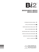
CONOSCIAMO IL Bi2
Bi2-SLIeSLIRg.1
Bi2-SLIeSLIRg.2
A - Struttura portante in
lamiera elettrozincata ad alta
resistenza.
B - Batteria di scambio
termico ad acqua fredda in
tubi di rame e alettatura a pacco
d’alluminio con turbolenziatura
ad alta efficienza. Raccordi
filettati tipo eurokonus3/4,
conformiallenuoveesigenzedi
standardizzazione comunitarie.
Labatteriaèequipaggiatadaun
sensoreperlarilevazionedella
temperaturadell’acqua(versione
SLR e SLI elettroniche).
C - Batteria di scambio
termico ad acqua calda in
tubi di rame e alettatura a
pacco d’alluminio. Raccordi
filettati tipo eurokonus3/4,
conformiallenuoveesigenzedi
standardizzazione comunitarie.
La batteria èequipaggiata da
uno specifico sensore per la
rilevazione della temperatura
dell’acqua(versioneSLReSLI
elettroniche).
MORE ABOUT THE Bi2
Bi2-SLIandSLIRg.1
Bi2-SLIandSLIRg.2
A - Supporting structure
in high resistance electro-
galvanised steel sheet.
B - Cold water heat
exchange battery in copper
pipesand aluminiumns with
high efficiency turbulence.
eurokonus ¾ type threaded
unions in compliance with the
new European community
standardisation requirements.
The battery is equipped with
a special sensor for detecting
the water temperature (SLI
electronic and SLR version).
C - Hot water heat exchange
battery in copper pipes and
aluminium fins. eurokonus
¾ type threaded unions
in compliance with the new
European community
standardisation requirements.
The battery is equipped with
a special sensor for detecting
the water temperature (SLI
electronic and SLR version).
DECOUVRONS LE Bi2
Bi2-SLIetSLIRg.1
Bi2-SLIetSLIRg.2
A - Structure portante en tôle
galvaniséehauterésistance.
B - Batterie d’échange
thermique à eau froide en
tubes de cuivreet ailettage
à paquet d’aluminium à
turbulence haute efficacité.
Raccordsletéstypeeurokonus
3/4, conformes auxnouvelles
exigencescommunautaires de
standardisation.
Labatterie estéquipée d’un
capteur de détection de la
températurede l’eau(version
SLRetSLIélectroniques).
C - Batterie d’échange
thermique à eau chaude en
tubes de cuivreet ailettageà
paquet d’aluminium. Raccords
filetéstype eurokonus3/4,
conformes aux nouvelles
exigences communautaires
de standardisation. La batterie
estéquipée d’uncapteur de
détection spécifique de la
températurede l’eau(version
SLRetSLIélectroniques).
Bi2 KENNEN
Bi2 - SLI und SLIR Abb. 1
Bi2 - SLI und SLIR Abb. 2
A - Tragkonstruktion
in hochbeständigem
elektroverzinktem Blech.
B - Kaltwasser-
Wärmetauscherbatterie
in Kupferrohren und
Aluminiumblock-Verrippung
mit hochwirksamer
Wirbelung. Gewindefittings
Typ Eurokonus 3/4, in
Übereinstimmung mit den neuen
Standardisierungsvorgaben der
Europäischen Gemeinschaft.
Die Batterie ist ausgestattet
mit einem Sensor zur
Wassertemperaturerfassung
(Ausführung SLR und SLI
elektronisch)
C - Warmwasser-
Wärmetauscherbatterie
in Kupferrohren und
Aluminiumblock.Gewindettings
Typ Eurokonus 3/4, in
Übereinstimmung mit den neuen
Standardisierungsvorgaben der
Europäischen Gemeinschaft.
Die Batterie ist ausgestattet
mit einem Spezialsensor zur
Wassertemperaturerfassung
(Ausführung SLR und SLI
elektronisch)
G
B
A
M
H
D
C
I

GB
F
D
20
I
D - Pannello radiante ad
elevata efficienza collegata
alla batteria ad acqua calda
(versioneSLR).
Perle versionia duetubiil
gruppoidraulicoèdotatodiuna
valvolacalostatche impedisce
l’ingresso dell’acqua fredda al
pannello.
E - Gruppo ventilante
comprendente ventilatore
tangenzialeinmaterialesintetico
ad alettesfalsate (elevata
silenziosità) montato su supporti
antivibrantiinEPDM,bilanciato
staticamenteedinamicamente,
calettato direttamente sull’albero
motore.
F - Motore elettrico a pacco
resinato montato su supporti
antivibrantiinEPDM.
G - Griglia aria mandata
reversibile in alluminio
verniciato con polveri
epossidiche (tinta argento
metallizzato) essiccate a forno.
Il generoso dimensionamento
neesaltal’elevataresistenza
meccanica.
H - Griglia aria aspirazione in
lamieraelettrozincataverniciata
con polveri epossidiche(tinta
argento metallizzato oRAL
9010)essiccate aforno, con
dispositivo di sganciamento
rapido per pulizia filtri e
microinterruttore di sicurezza.
I - Mantello frontaleeanchi
laterali smontabili in lamiera
elettrozincataverniciata con
polveri epossidiche (tinta
argento metallizzato oRAL
9010) essiccate a forno
(versioneSLR4T).
L - Schienale strutturale
anticondensa ad alta resistenza.
1
D - Heating plate; high
efciencyandconnectedtothe
hot water battery (SLR version).
For the versions with two pipes
thehydraulicunitisttedwitha
calostat valve that prevents cold
water from ntering the plate.
E - Ventilating unit consisting
of a tangential fan with unphased
blades in synthetic material
(extremely quiet) mounted
on anti-vibration supports in
EPDM, balanced statically and
dynamically, and splined directly
onto the motor shaft.
F - Electric motor, with resin-
coated coil mounted on anti-
vibration supports in EPDM.
G - Reversible air outlet
grill in aluminium painted with
epoxy powder paint (metallic
silver colour) and oven-dried.
The large size exalts its high
mechanical resistance.
H - Air suction grill in electro-
galvanised steel sheet painted
with epoxy powders (metallic
silver colour or RAL 9010) and
oven dried, with rapid release
device for filter cleaning and
safety micro-switch.
I - Dismountable front casing
and lateral plates made from
electro-galvanised steel sheet
painted with epoxy powders
(metallic silver colour or RAL
9010) and oven dried (SLR
4-pipe version).
L - Structural back-plate,
anti-condensation and high
resistance.
D - Panneau rayonnant haute
efcacité reliée à la batterieà
eauchaude(versionSLR).
Pourlesversionsàdeuxtubes,
legroupehydrauliqueestdoté
d’unevalveCalorstatempêche
l’entrée de l’eau froide sur le
panneau.
E - Groupe de ventilation
comprenant un ventilateur
tangentiel en matériau
synthétique à ailettes en
quinconce (très silencieux),
montésur dessupports anti-
vibrationsen EPDM,équilibré
statiquementetdynamiquement,
calé directement sur l’arbre
moteur.
F - Moteur électrique à paquet
résinémontésursupportsanti-
vibrationsenEPDM.
G - Grille air refoulement
réversible en aluminium peint à
lapeintureépoxy(teinteargent
métallisé),séchéeaufour.Ses
dimensions généreuses en
mettentenvaleurlarésistance
mécaniqueélevée.
H - Grille air aspiration en tôle
galvaniséepeinteàlapeinture
époxy (teinte argent métallisé
ou RAL9010), séchéau four,
avecdispositif dedécrochage
rapidepournettoyageltreset
micro-interrupteurdesécurité.
I - Manteau frontal et ancs
latéraux démontables en tôle
galvaniséepeinteàlapeinture
époxy (teinte argent métallisé
ouRAL9010),séchéeaufour
(versionSLR4T).
L - Dossierstructurel anti-
condensationhauterésistance.
D -
Wärmewellenheizung
,
mit hohem Wirkungsgrad,
angeschlossen an die
Warmwasserbatterie
(Ausführung SLR).
Bei den Ausführungen
mit zwei Schläuchen ist die
Wassergruppe mit einem
Calostat-Ventil ausgestattet,
dasdenZuussdes
Kaltwassers
zur Strahlplatte unterbindet.
E - Belüftungsgruppe,
mit Tangentialventilator
aus Kunststoff und
versetzten Rippen (hohe
Geräuschdämpfung), montiert
auf schwingungsdämpfenden
Halterungen aus EPDM,
statisch und dynamisch
abgeglichen, direkt auf die
Motorwelle aufgezogen.
F - Elektromotor, Block mit
Harzüberzug, montiert auf
schwingungsdämpfenden
Halterungen aus EPDM.
G - Umkehrbarer Zuluftrost
aus mit Epoxidpulvern
lackiertem Aluminium (Farbton
Metallic-Grau), ofengetrocknet.
Die großzügige Bemessung
verstärkt die hohe mechanische
Festigkeit.
H - Saugluftrost aus mit
Epoxidpulvern lackiertem,
elektroverzinktem Blech
(Farbton Metallic-Grau oder
RAL 9010), ofengetrocknet, mit
chnellauskupplungsvorrichtung
zur Filterreinigung und
Sicherheitsmikroschaltern.
I - Vordermantel und
Seitenankenabmontierbar,aus
mit Epoxidpulvern lackiertem,
elektroverzinktem Blech
(Farbton Metallic-Grau oder
RAL 9010), ofengetrocknet
(Version SLR 4T).
L -
Hochbeständige
Kondensflüssigkeitsschutz-
Rückseitenstruktur.

GB
F
D
22
I
DIMENSIONI D’INGOMBRO
Bi2 2 TUBI
Vederegura3efareriferimento
al modello in possesso.
DIMENSIONI D’INGOMBRO
Bi2 4 TUBI
Vederegura4efareriferimento
al modello in possesso.
A (mm) 525 725 925 1125 1325
1.7
1.8
1
3
OVERALL DIMENSIONS Bi2
2 PIPES
See gure 3 and refer to the
model in question.
OVERALL DIMENSIONS Bi2
4 PIPES
See gure 4 and refer to the
model in question.
DIMENSIONS HORS TOUT Bi2
2 TUBES
Voir gure 3 et sereporter au
modèlepossédé.
DIMENSIONS HORS TOUT Bi2
4 TUBES
Voir gure 4 et sereporter au
modèlepossédé.
AUSSENABMESSUNGEN Bi2
2 SCHLÄUCHE
Siehe Abbildung 3. Nehmen Sie
Bezug auf das Modell in Ihrem
Besitz.
AUSSENABMESSUNGEN Bi2
4 SCHLÄUCHE
Siehe Abbildung 4. Nehmen Sie
Bezug auf das Modell in Ihrem
Besitz.
SLI200
SLIR200
SLI400
SLIR400
SLI600
SLIR600
SLI800
SLIR800
SLI1000
SLIR1000

E P NL
23
GR
4
SLI200 SLI400 SLI600 SLI800 SLI1000
A (mm) 525 725 925 1125 1325
SLR200 SLR400 SLR600 SLR800 SLR1000
A (mm) 697 897 1097 1297 1497
1
RUIMTEBESLAG Bi2 2
LEIDINGEN
Zieafbeelding 3enhet model
inuwbezit.
RUIMTEBESLAG Bi2 4
LEIDINGEN
Zieafbeelding 4enhet model
inuwbezit.
DIMENSÕES EXTERNAS Bi2
2 TUBOS
Veragura3ecompararcomo
modelo em vosso poder.
DIMENSÕES EXTERNAS Bi2
4 TUBOS
Veragura4ecompararcomo
modelo em vosso poder.
ÄÉÁÓÔÁÓÅÉÓ ÏÃÊÏÕ Bi2 2
ÓÙËÇÍÙÍ
Äåßôå åéêüíá 3 êáé åîåôÜóôå
ôï ìïíôÝëï ðïõ Ý÷åôå óôçí
êáôï÷Þ óáò.
ÄÉÁÓÔÁÓÅÉÓ ÏÃÊÏÕ Bi2 4
ÓÙËÇÍÙÍ
Äåßôå åéêüíá 4 êáé åîåôÜóôå
ôï ìïíôÝëï ðïõ Ý÷åôå óôçí
êáôï÷Þ óáò.
DIMENSIONES Bi2 2 TUBOS
Véaselagura3yremítaseal
modelo correspondiente.
DIMENSIONES Bi2 4 TUBOS
Véaselagura4yremítaseal
modelo correspondiente.
1.7
1.8

GB
F
D
24
I
CARATTERISTICHE
TECNICHE NOMINALI
VERSIONE Bi2 2 TUBI
Vedere tabella di gura 5 e
fare riferimento al modello in
possesso.
A Contenuto acqua batteria
B Contenuto acqua pannello
radianteversioneSLIR
C Pressione massima
esercizio
D Massima temperatura
ingressoacqua
E Minima temperatura
ingressoacqua
F Attacchi idraulici
G Tensione di alimentazione
H Peso SLI
I Peso SLIR
Per i dati degli assorbimenti
elettricifareriferimentoallatarga
delle caratteristiche tecniche
dell’unità.
CARATTERISTICHE
TECNICHE NOMINALI
VERSIONE Bi2 4 TUBI
Vedere tabella di gura 6 e
fare riferimento al modello in
possesso.
A Contenuto acqua batteria
raffrescamento
B Contenuto acqua batteria
riscaldamento
C Contenuto acqua pannello
radianteversioneSLR
D Pressione massima esercizio
E Massima temperatura
ingressoacqua
F Minimatemperaturaingresso
acqua
G Attacchi idraulici
H Tensione di alimentazione
I Peso SLR
L Peso SLI
Per i dati degli assorbimenti
elettricifareriferimentoallatarga
delle caratteristiche tecniche
dell’unità.
5
1.9
1.10
1
NOMINAL TECHNICAL
FEATURES Bi2 2 PIPE
VERSION
Refer to the data for the respective
modelinthetableingure5.
A Battery water contents
B Radiant plate water content
version SLIR
Maximum working pressure
D Maximum water inlet
temperature
E Minimum inlet water
temperature
F Hydraulicxtures
G Power supply
H Weight SLI
I Weight SLIR
For information on electrical
consumption see the technical
features plate on the unit.
NOMINAL TCHNICAL
FEATURES Bi2 4 PIPE
VERSION
Refer to the data for the respective
modelinthetableingure6.
A Cooling battery water
contents
B Heating battery water
contents
C Radiant plate water content
version SLR
D Maximum working pressure
E Maximum water inlet
temperature
F Minimum inlet water
temperature
G Hydraulicxtures
H Power supply
I Weight SLR
L Weight SLI
For information on electrical
consumption see the technical
features plate on the unit.
CARACTERISTIQUES
TECHNIQUES NOMINALES
VERSION Bi2 2 TUBES
Voirtableaudelagure5etse
reporteraumodèlepossédé.
A Contenu eau batterie
B Contenu eau panneau
rayonnantversionSLIR
C Pressionmaximumde
service
D Températuremaximum
d’entréeeau
E Températureminimum
d’entréeeau
F Priseshydrauliques
G Tension d’alimentation
H Poids SLI
I Poids SLIR
Pourlesdonnéesdesabsorptions
électriques, se reporter à la
plaquedescaractéristiquesde
l'unité.
CARACTERISTIQUES
TECHNIQUES NOMINALES
VERSION Bi2 4 TUBES
Voirtableaudelagure6etse
reporteraumodèlepossédé.
A Contenu eau batterie
refroidissement
B Contenu eau batterie
chauffage
C Contenu eau panneau
rayonnantversionSLR
D Pression maximum de
service
E Température maximum
d’entréeeau
F Température minimum
d’entréeeau
G Priseshydrauliques
H Tension d’alimentation
I Poids SLR
L Poids SLI
Pourlesdonnéesdesabsorptions
électriques, se reporter à la
plaquedescaractéristiquesde
l'unité.
TECHNISCHE NENN-
EIGENSCHAFTEN
AUSFÜHRUNG Bi2 2
SCHLÄUCHE
Siehe Abbildung 5. Nehmen Sie
Bezug auf das Modell in Ihrem
Besitz.
A Wasserinhalt Batterie
B Wasserinhalt
Wärmewellenheizung
Version SLIR
C Maximaler Betriebsdruck
D Maximale
Einlaufwassertemperatur
E Einlaufwasser-
Mindesttemperatur
F Wasseranschlüsse
G Versorgungsspannung
H Gewicht SLI
I Gewicht SLIR
Entnehmen Sie die
Stromaufnahmewerte dem
Typenschild mit den technischen
Daten der Einheit.
TECHNISCHE NENN-
EIGENSCHAFTEN
AUSFÜHRUNG Bi2 4
SCHLÄUCHE
Siehe Abbildung 6. Nehmen Sie
Bezug auf das Modell in Ihrem
Besitz.
A Wasserinhalt Kühlbatterie
B Wasserinhalt Heizbatterie
C Wasserinhalt
Wärmewellenheizung
Version SLR
D Maximaler Betriebsdruck
E Maximale
Einlaufwassertemperatur
F Einlaufwasser-
Mindesttemperatur
G Wasseranschlüsse
H Versorgungsspannung
I Gewicht SLR
L Gewicht SLI
Entnehmen Sie die
Stromaufnahmewerte dem
Typenschild mit den technischen
Daten der Einheit.
l
l
bar
°C
°C
“
V/ph/Hz
kg
A
B
C
D
E
F
G
H
200
0,47
0.5
10
80
4
Eurokonus 3/4
230/1/50
9
400
0,8
0.6
10
80
4
Eurokonus 3/4
230/1/50
12
600
1,13
0,7
10
80
4
Eurokonus 3/4
230/1/50
15
800
1,46
0,9
10
80
4
Eurokonus 3/4
230/1/50
18
1000
1,8
1
10
80
4
Eurokonus 3/4
230/1/50
21

GB
F
D
26
I
2
2.1
2.2
INSTALLAZIONE
POSIZIONAMENTO
DELL’UNITA’
Evitare l’installazione
dell’unità in prossimità di:
- posizioni soggette
all’esposizione diretta dei
raggisolari;
- inprossimitàdifontidicalore;
- in ambientiumidi ezone
con probabile contatto con
l’acqua;
- inambienticonvaporid’olio
- inambientisottopostiadalte
frequenze.
Accertarsi che:
- la paretesu cui siintende
installare l’unità abbia una
struttura e una portata
adeguata;
- la zona della parete
interessata non sia percorsa
da tubazioni o linee elettriche
- laparete interessatasia
perfettamenteinpiano;
- sia presenteun’area libera
da ostacoli che potrebbero
compromettere la circolazione
dell’ariainingressoeduscita;
- laparete di installazionesia
possibilmente una parete
di perimetro esterno per
consentire lo scarico della
condensaall’esterno;
- in casodi installazionea
soffitto(versione SLI) il
flusso dell’aria non sia
rivoltodirettamente versole
persone.
MODALITA’ D’INSTALLAZIONE
Le seguenti descrizioni sulle
varie fasi dimontaggio edi
relatividisegnifannoriferimento
ad una versionedi macchina
con attacchi a sinistra.
Le descrizioni per le operazioni
dimontaggio dellemacchine
con attacchi a destra sono le
medesime.
Solo le immagini sono da
considerarsi rappresentate
specularmente.
Per ottenere una buona riuscita
dell’installazione e prestazioni
di funzionamento ottimali,
seguireattentamente quanto
indicato nel presente manuale.
La mancata applicazione
dellenorme indicate,che può
causare mal funzionamenti
delleapparecchiature,sollevano
la ditta OLIMPIA SPLENDID
da ogni formadi garanziae
daeventuali dannicausati a
persone,animaliocose.
INSTALLATION
POSITIONING THE UNIT
Avoid installing the unit in
proximity to:
- positions subject to exposure
to direct sunlight;
- in proximity to sources of
heat;
- in damp areas or places with
probable contact with water;
- in places with oil fumes
- places subject to high
frequencies.
Make sure that:
- the wall on which the unit is to
be installed is strong enough
to support the weight;
- the part of the wall interested
does not have pipes or electric
wires passing through;
- the interested wall is perfectly
at;
- there is an area free
of obstacles which could
interfere with the inlet and
outletairow;
- the installation wall is
preferably an outside
perimeter wall to allow the
discharge of the condensation
outside;
- in case of ceiling installation
(SLIversion)theairowisnot
directed towards persons.
INSTALLATION MODES
The following descriptions of
the various mounting phase
and the relative designs refer
to a version of the machine with
xturesontheleft.
The operations for the mounting
ofmachineswithxturesonthe
right are exactly the same.
Only the images are to be
considered as a mirror image.
To ensure that the installation is
performed correctly and that the
appliance will perform perfectly
carefully follow the instructions
indicated in this manual. Failure
to respect the rules indicated not
only can cause malfunctions
of the appliance but will also
invalidate the warranty and
hence OLIMPIA SPLENDID
shall not respond for any
damage to persons, animals or
property.
INSTALLATION
MISE EN PLACE
DE L’UNITE
Eviter l’installation de l’unité
à proximité de :
- positions soumises à
l’exposition directe aux
rayonssolaires;
- à proximité desources de
chaleur;
- dansdes endroitshumides
ou des zones de contact
probableavecl’eau;
- dans deslocaux présentant
desvapeursd’huile
- dansdeslocauxsoumisàdes
hautesfréquences.
S’assurer que:
- lemursurlequell’onprévoit
d’installerl’unité présente
unestructureetunecapacité
appropriées;
- la zonedu mur concernée
n’est pas parcourue par
des tubesou des lignes
électriques
- le mur concerné est
parfaitementplan;
- est présente une zone
libred’obstacles pouvant
compromettre la circulation
del’airàl’entréeetàlasortie;
- lemurd’installationestdans
la mesure du possible un mur
de périmètre externepour
permettrel’évacuation des
condensatsàl’extérieur;
- encasd’installationauplafond
(versionSLI),leuxd’airn’est
pasorientédirectementvers
les personnes.
MODALITES D’INSTALLATION
Les descriptions suivantes
sur les différentes phases
de montage etles dessins
correspondants se réfèrent à
uneversiondelamachineayant
lesprisesàgauche.
Les descriptions pour les
opérations de montagedes
machines ayant lesprises à
droite sont les mêmes.
Seulementles imagesdoivent
être considérées comme
représentées de façon
spéculaire.
Pour obtenir une bonne
installation et des performances
de fonctionnement optimales,
suivre attentivement les
indications du présent
manuel. Le non respect des
instructions,qui peutentraîner
des dysfonctionnements des
appareils,déchargentlasociété
OLIMPIA SPLENDID de toute
formede garantieet detoute
responsabilitéconcernant les
dommageséventuelscausésà
despersonnes,desanimauxou
des biens.
INSTALLATION
POSITIONIERUNG DER
EINHEIT
Vermeiden Sie die Installation
der Einheit in der Nähe von:
- direkt an Sonnenstrahlen
ausgesetzten Stellen
- in der Nähe von Wärmequellen
- in feuchten Umgebungen und
Zonen mit möglichem Kontakt
mit Wasser
- in Umgebungen mit Öldampf
- in hohen Frequenzen
ausgesetzten Umgebungen
Stellen Sie sicher, dass:
- die Wand, an der die Einheit
installiert werden soll, einen
angemessene Struktur und
Tragfähigkeit hat.
- im betreffenden Wandbereich
keine Rohrleitungen oder
elektrischen Leitungen
verlaufen.
- der betreffende Wandbereich
vollkommen eben ist.
- ein von Hindernissen, welche
die Zirkulation der Zu- und
Abluft behindern könnte,
freier Bereich vorhanden ist.
- Die Installationswand
sollte möglichst eine
Außenumfangswand sein,
sodass die Abführung der
Kondensflüssigkeit nach
außen möglich ist.
- Bei der Deckeninstallation
(Ausführung SLI) darf der
Luftstrom nicht unmittelbar
auf Personen gerichtet sein.
INSTALLATIONSHINWEISE
Die nachfolgenden
Beschreibungen der
verschiedenen Montagephasen
und die zugehörigen
Zeichnungen beziehen sich auf
eine Maschinenausführung mit
Anschlüssen auf der linken Seite.
Die Beschreibungen für die
Montagearbeiten bei Maschinen
mit Anschlüssen auf der rechten
Seite sind dieselben.
Nur die Abbildungen sind
spiegelverkehrt zu betrachten.
Zur Gewährleistung einer
einwandfreien Installation und
optimaler Betriebsleistungen
sind die Anweisungen in diesem
Handbuch strikt zu befolgen.
Die nicht erfolgte Anwendung
der angegebenen Vorschriften
kann Betriebsstörungen an
den Geräten verursachen und
entbindet die Firma OLIMPIA
SPLENDID aus jeder Form der
Gewährleistungspflicht sowie
der Haftung für eventuelle
Schäden an Personen, Tieren
oder Gegenständen.

GB
F
D
28
I
2.3
2.4
2
7
L’apparecchio deveessere
installato in una posizione tale
da consentire facilmente la
manutenzione ordinaria (pulizia
del filtro) e straordinaria,
nonchèl’accesso allevalvole
di sfiato dell’aria (batteria e
piastre)raggiungibilidallagriglia
superiore,latoattacchi.
DISTANZE MINIME DI
INSTALLAZIONE
Nella gura 7 sonoindicate le
distanze minime di montaggio
del ventilconvettore da pareti
e mobili presenti nell’ambiente.
APERTURA FIANCHI
- Smontarelagrigliasuperiore
(g.8rif.A)svitandoledue
vitidi fissaggio(fig. 8rif.
B).
- Aprire losportello laterale
(g.8rif.C).
- Sul latosinistro svitarela
vite(g.8 rif.F) chessail
anchetto sinistro (g.8 rif.
G),spostarloleggermente
versosinistraesollevarlo.
- Sul altoopposto sollevareil
coperchietto(g. 8rif. H) di
coperturavite(g.8rif.L)e
svitarla.
- Spostareleggermenteverso
destrailanchettoesollevarlo
(g.8rif.P).
The appliance must be installed
in a position that allows the
routine maintenance (filter
cleaning) and the extraordinary
interventions to be carried out
easily, giving access to the air
breather valves (battery and
plates), reachable from the
uppergrillonthexturesside.
MINIMUM INSTALLATION
DISTANCES
Figure7indicatestheminimum
mounting distances between the
wall-mounted cooler-convector
and furniture present in the room.
SIDE OPENING
- Dismounttheuppergrill(g.8
ref. A) by unscrewing the two
xingscrews(g.8ref.B).
- Openthesideinspectionap
(g.8ref.C).
- On the left-hand side loosen
thescrew (g.8 ref.F) that
xestheleftpanel(g.8ref.
G), then move it slightly to the
left and lift it up.
- On the opposite side, lift
thecover (g.8 ref.H)that
protectsthescrew(g.8ref.
L) and unscrew it.
- Move the side panel slightly
totherightandliftitout(g.
8 ref. P).
L’appareil doitêtre installé
dans une position permettant
facilement l’entretien ordinaire
(nettoyage du filtre) et
extraordinaire,ainsiquel’accès
auxvalves d’évent(batterie et
plaques)accessiblesparlagrille
supérieure,côtéprises.
DISTANCES MINIMUM
D’INSTALLATION
Lagure7indiquelesdistances
minimum de montage du
ventilateur-convecteurmuralet
mobileprésentdanslapièce.
OUVERTURE FLANCS
- Démonterlagrillesupérieure
(g.8réf.A)endévissantles
deuxvisdexation(g.8réf.
B).
- Ouvrirleportillonlatéral(g.
8réf.C).
- Surlecôtégauche,dévisser
lavis(g.8réf.F)quixele
ancgauche(g.8réf.G),le
déplacerlégèrement versla
gaucheetlesoulever.
- Surlecôtéopposé,soulever
le cache (fig.8 réf.H) de
couverturevis(g.8réf.L)et
ladévisser.
- Déplacerlégèrementleanc
versla droiteet lesoulever
(g.8réf.P).
Das Gerät ist in einer
Position zu installieren, die
eine leichte programmierte
Wartung (Filterreinigung) und
außerordentliche Wartung
sowie den Zugriff auf die
Entlüftungsventile (Batterien
und Platten), die vom oberen
Rost aus erreicht werden können
(anschlussseitig), zulässt.
MINDEST-
INSTALLATIONSABSTÄNDE
In der Abbildung 7 sind die
Mindest-Installationsabstände
des Ventil-Konvektors von
Wänden und Möbeln im Raum
angegeben.
ÖFFNUNG DER SEITEN
- Montieren Sie den oberen
Rost (Abb. 8 Pos. A) ab,
indem Sie die beiden
Befestigungsschrauben (Abb.
8 Pos. B) lösen.
- Öffnen Sie die seitliche
Abdeckung (Abb. 8 Pos. C).
- Lösen Sie auf der linken
Seite die Schraube (Abb. 8
Pos. F) zur Befestigung des
linken Flügels(Abb. 8 Pos. G),
versetzen diesen leicht nach
links und heben ihn an.
- Entfernen Sie auf der
gegenüberliegenden Seite
die Schutzkappe (Abb. 8 Pos.
H) der Schraube (Abb. 8 Pos.
L) nach oben und lösen die
Schraube.
- Verschieben Sie den Flügel
leicht nach rechts und
entfernen diesen nach oben
(Abb. 8 Pos. P).

GB
F
D
30
I
12
INSTALLAZIONE A PARETE O
PAVIMENTO VERTICALE
In caso di montaggio a
pavimentocon glizoccoli, per
ilmontaggio diquesti, fare
riferimento ai singoli fogli
istruzione in dotazione e al
manualerelativo.
Utilizzare la dimadi carta,
e tracciare sulla parete la
posizione delle due staffe di
fissaggio(fig. 9).Forare con
unapuntaadeguataedinlare
itasselli(2perognistaffa)(g.
10 rif.A);ssare ledue staffe
(fig.10 rif.B). Nonstringere
eccessivamente le viti, in
modo da poter effettuare una
regolazionedellestaffeconuna
bolladilivello(g.11).
Bloccaredenitivamenteledue
staffe serrando completamente
lequattroviti.
Vericarnelastabilitàspostando
manualmentele staffeverso
destraesinistra,altoebasso.
Montare l’unità, verificandoil
correttoagganciosullestaffee
lasuastabilità(g.12).
2.5
A AB
B
10
9
VERTICAL FLOOR OR WALL
INSTALLATION
When mounting on the floor
with support feet, refer to the
individual instructions leaets
supplied and the relative manual
for the mounting of the feet.
Using the paper template, trace
the position of the two fixing
bracketsonthewall(g.9).Use
a suitable drill to make the holes
with and insert the toggle bolts
(2foreachbracket)(g.10ref.
A);xthetwobrackets(g.10
ref. B). Do not over-tighten the
screws so that the brackets can
be adjusted with a spirit level
(g.11).
Fully tighten the four screws to
block the two brackets.
Check the stability by manually
moving the brackets to the right
and to the left, up and down.
Mount the unit, checking that it
tscorrectly ontothe brackets
and checking that it is stable
(g.12).
INSTALLATION MURALE OU
AU SOL VERTICALE
Encasdemontageausolavec
lessocles,pourlemontagede
cesderniers, sereporter aux
chesd’instructionsfournieset
au manuel correspondant.
Utiliser le gabarit en papieret
tracer sur le mur la position des
deuxétriersdexation(g.9).
Perceravecunforetapproprié
etinsérer leschevilles (2par
étrier)(g.10réf.A);xerles
deuxétriers(g.10réf.B).Ne
pastropserrerlesvis,defaçon
àpouvoir effectuerun réglage
des étriers avecun niveau
(g.11).
Bloquerdénitivementlesdeux
étriersenserrantcomplètement
lesquatrevis.
En vérifier la stabilité en
déplaçant manuellement les
étriersversladroite et vers la
gauche,lehautetlebas.
Monter l’unité,en vérifiant
l’accrochage sur lesétriers et
sastabilité(g.12).
INSTALLATION AN DER WAND
ODER AM FUSSBODEN /
VERTIKAL
Bei Installation am Fußboden
mit den Sockeln ist bei der
Montage derselben Bezug auf
die einzelnen mitgelieferten
Anweisungsblätter und das
zugehörige Handbuch Bezug
zu nehmen.
Verwenden Sie die
Papierschablone (Abb. 9) und
zeichnen Sie an der Wand
die Position der beiden
Befestigungsbügel (Abb. 9)
vor. Bohren Sie mit einem
geeigneten Bohrer und führen
Sie die Dübel ein (2 pro Bügel)
(Abb. 10 Pos. A); Sichern Sie
die beiden Bügel (Abb. 10 Pos.
B). Ziehen Sie die Schrauben
nicht zu fest an, damit eine
Regulierung des Bügels mit Hilfe
einer Wasserwaage möglich ist
(Abb. 11).
Blockieren Sie die beiden
Bügel endgültig, indem Sie
die vier Schrauben vollständig
festdrehen.
Überprüfen Sie die Stabilität,
indem Sie die Bügel von Hand
nach rechts und links, oben und-
unten verstellen.
Montieren Sie die Einheit, wobei
Sie die das korrekte Einhängen
auf den Bügeln und die Stabilität
prüfen (Abb. 12).

GB
F
D
32
I
12
2.6
2.7
2.7.1
13
A A
B
B
CD
HORIZONTAL OR CEILING
INSTALLATION
This installation is not
permitted for the "Full Flat"
version.
Using the paper template, trace
on the ceiling the position of the
twoxingbracketsandthetwo
rear screws. Using a suitable
drill, make the holes and insert
the toggle bolts (2 for each
bracket)(g.13ref.A);xthe
two brackets (fig. 13 ref. B).
Do not over-tighten the screws.
Position the machine on the two
brackets, keeping it in position
andthenxthetwoscrewsinto
thereartogglebolts(g.13ref.
C), one on each side.
Makesurethatthereissufcient
inclination of the unit towards the
drainage pipe to facilitate the
waterdrainage(g.13ref.D).
Fullytightenall6xingscrews.
HYDRAULIC CONNECTIONS
Pipeline diameter
The minimum internal diameter
that must be respected for
the pipelines of the hydraulic
connections varies according
to the model:
SLI/SLIR/SLR 200 ø12 mm
SLI/SLIR/SLR 400 ø14 mm
SLI/SLIR/SLR 600 ø16 mm
SLI/SLIR/SLR 800 ø18 mm
SLI/SLIR/SLR 1000 ø20 mm
For the position of the pipeline
and the wall fixings, refer
to the designs shown in the
following sections, based on
the specic conguration.
INSTALLATION AU PLAFOND
OU HORIZONTALE
Cette installation n'est pas
permise pour la version "Full
Flat".
Utiliser le gabarit en papieret
tracer au plafond la position des
deuxétriers dexation etdes
deuxvis arrière.Percer avec
unforetappropriéetinsérerles
chevilles(2parétrier)(g.13
réf.A);xerlesdeuxétriers(g.
13réf. B).Ne pastropserrer
lesvis.
Mettre en place la machine sur
lesdeuxétriers,enlamaintenant
enposition,puisxerlesdeux
visdansleschevillesarrière(g.
13réf.C),uneparcôté.
Ilest conseilléde conférer
une inclinaisonappropriée
del’appareil versle tubede
drainagepourfaciliterla sortie
del’eau(g.13réf.D).
Serrerdénitivement les6 vis
dexation.
BRANCHEMENTS
HYDRAULIQUES
Diamètre tubes
Le diamètre interneminimum
à respecter pour les tubes des
branchementshydrauliques
varieselonlemodèle:
SLI/SLIR/SLR 200 ø12 mm
SLI/SLIR/SLR 400 ø14 mm
SLI/SLIR/SLR 600 ø16 mm
SLI/SLIR/SLR 800 ø18 mm
SLI/SLIR/SLR 1000 ø20 mm
Pour la position des tubes
pour les prises
murales, voir les dessins
figurant aux paragraphes
suivants, sur la base de la
conguration spécique.
INSTALLATION AN DER
DECKE ODER HORIZONTAL
Bei den "Full Flat" Modellen ist
die horizontale Installation nicht
zulässig.
Verwenden Sie die Papierschablone
und zeichnen Sie an der
Decke die Position der beiden
Befestigungsbügel und der beiden
hinteren Schrauben vor. Bohren
Sie mit einem geeigneten Bohrer
und führen Sie die Dübel ein (2 pro
Bügel) (Abb. 13 Pos. A); Sichern
Sie die beiden Bügel (Abb. 13 Pos.
B). Ziehen Sie die Schrauben nicht
zu fest an
Führen Sie die Maschine auf den
beiden Bügeln ein, wobei Sie die
Position erhalten, und befestigen
anschließend die beiden Schrauben
in den hinteren Dübeln (Abb. 13
Pos. C), jeweils eine pro Seite.
Bitte achten Sie unbedingt auf eine
angemessene Neigung der Einheit in
Richtung des Entwässerungsrohrs,
um das Austreten des Wassers zu
unterstützen (Abb. 13 Pos. D).
Ziehen Sie alle 6
Befestigungsschrauben endgültig
fest.
WASSERANSCHLÜSSE
Durchmesser der
Schlauch-/Rohrleitungen
Der einzuhaltende
Mindestdurchmesser für
die Rohrleitungen der
Wasseranschlüsse ist je nach
Modell unterschiedlich:
SLI/SLIR/SLR 200 ø12 mm
SLI/SLIR/SLR 400 ø14 mm
SLI/SLIR/SLR 600 ø16 mm
SLI/SLIR/SLR 800 ø18 mm
SLI/SLIR/SLR 1000 ø20 mm
Bezüglich der Position der
Schlauch-/Rohrleitungen für
die Wandanschlüsse nehmen
Sie je nach spezifischer
Konguration Bezug auf die in
den nachfolgenden Abschnitten
wiedergegebenen Zeichnungen.
INSTALLAZIONE A SOFFITTO
O ORIZZONTALE
Questa installazione non è
consentita per la versione
"Full Flat".
Utilizzarela dimadi carta,e
tracciareasofttolaposizione
delle due staffedi ssaggio e
delleduevitiposteriori.Forare
con una puntaadeguata ed
infilarei tasselli(2 per ogni
staffa)(g.13 rif.A);ssare le
due staffe (g. 13rif. B).Non
stringereeccessivamenteleviti.
Infilare la macchina sulle
due staffe, mantenendolain
posizionequindissareledue
vitineitasselliposteriori(g.13
rif.C),unaperognilato.
Si raccomanda di conferire
un’adeguata inclinazione
dell’unità verso il tubo di
drenaggio per agevolarela
fuoriuscitadell’acqua (fig.13
rif. D).
Stringeredenitivamentetuttele
6vitidissaggio.
COLLEGAMENTI IDRAULICI
Diametro tubazioni
Il diametro interno minimo da
rispettare per le tubazioni dei
collegamentiidraulici variaa
secondodelmodello:
SLI/SLIR/SLR 200 ø12 mm
SLI/SLIR/SLR 400 ø14 mm
SLI/SLIR/SLR 600 ø16 mm
SLI/SLIR/SLR 800 ø18 mm
SLI/SLIR/SLR 1000 ø20 mm
Per la posizione delle
tubazioni per gli attacchi a
parete fare riferimento ai
disegni riportati nei paragra
successivi, in base alla
specica congurazione.

GB
F
D
34
I
12
Collegamenti
La scelta ed il dimensionamento
delle linee idrauliche è
demandato per competenza al
progettista,che dovràoperare
secondoleregole della buona
tecnicae dellelegislazioni
vigenti.
Pereffettuareicollegamenti:
- posizionarelelineeidrauliche
- serrare le connessioni
utilizzandoilmetodo“chiave
controchiave”(g.14rif.B)
- vericare l’eventualeperdita
di liquido
- rivestire leconnessioni con
materialeisolante(g.14rif.
C).
Le linee idrauliche e le
giunzionidevonoessereisolate
termicamente.
Evitareisolamentiparzialidelle
tubazioni.
Evitaredi stringeretroppo per
nondanneggiarel’isolamento.
Per la tenuta idrica delle
connessioni lettate utilizzare
canapaepastaverde;l’utilizzo
dinastroditeonèconsigliato
inpresenza diliquido antigelo
nel circuito idraulico.
2.7.2
14
A B
C
Connections
The choice and sizing of the
hydraulic lines must be made
by an expert who must operate
according to the rules of good
technique and the laws in force.
To make the connections:
- position the hydraulic lines
- tighten the connections using
the “spanner and counter
spanner”method(g.14ref.
B)
- check for any leaks of liquid
- coat the connections with
insulatingmaterial(g.14ref.
C).
The hydraulic lines and joints
must be thermally insulated.
Avoid partially insulating the
pipes.
Do not over-tighten to avoid
damaging the insulation.
Use hemp and green paste to
seal the threaded connections;
the use of Teflon is advised
when there is anti-freeze in the
hydraulic circuit.
Branchements
Lechoixetledimensionnement
des lignes hydrauliques
incombent au concepteur, qui
doitseconformerauxrèglesde
l’artetàlalégislationenvigueur.
Poureffectuerlesbranchements:
- mettre enplace leslignes
hydrauliques
-serrer lesconnexionsen
utilisant la méthode“clef
contreclef”(g.14réf.B)
- vérier l’éventuelleperte de
liquide
- revêtir lesconnexions avec
dumatériau isolant(g. 14
réf.C).
Leslignes hydrauliqueset les
jonctions doivent êtreisolées
thermiquement.
Eviterles isolationspartielles
des tubes.
Eviterdetropserrerpournepas
abîmerl’isolation.
Pourl’étanchéitédesconnexions
letées, utiliser duchanvre et
de la pâteverte ;l’utilisation
deTéflon estconseillée en
présencedeliquideantigeldans
lecircuithydraulique.
Anschlüsse
Wahl und Bemessung der
Wasserleitungen unterliegen der
Zuständigkeit des Entwurfs, der
gemäß den Regeln der Kunst
und den geltenden Gesetzen
durchzuführen ist.
Zur Herstellung der Anschlüsse:
- Positionieren Sie die
Wasserleitungen
- Ziehen Sie die Verbindungen
mit der "Schlüssel-gegen-
Schlüssel" Methode fest (Abb.
14 Pos. B)
- Überprüfen Sie den möglichen
Flüssigkeitsverlust.
- Umhüllen Sie die
Verbindungen mit
Isoliermaterial (Abb. 14 Pos.
C).
Wasserleitungen und
Verbindungsstellen sind
thermisch zu isolieren.
Vermeiden Sie partielle
Isolierungen der Rohrleitungen.
Vermeiden Sie einen zu festen
Anzug, um die Rohrleitungen
nicht zu beschädigen.
Verwenden Sie Hanf
und grüne Paste zur
wasserfesten Abdichtung der
Gewindeverbindungen. Die
Verwendung von Teflonband
empehltsichbeiVorhandensein
von Frostschutzmittel im
Wasserkreislauf nicht.

GB
F
D
36
I
SCARICO CONDENSA
La rete di scarico della condensa
deve essere opportunamente
dimensionata (diametro interno
tubo minimo 16 mm) e la
tubazione posizionata in modo
da mantenere semprelungo
il percorso una determinata
pendenza, mai inferiorea 1%.
Nell’installazione verticale
iltubo discarico sicollega
direttamente alla vaschetta di
scarico,posizionata inbasso
sulla spalla laterale,sotto gli
attacchi idraulici.
Nell’installazione orizzontale il
tubodiscaricovieneallacciato
a quello giàpresente sulla
macchina.
- Se possibilefare defluire
il liquido di condensa
direttamenteinunagrondaia
o in unoscarico di“acqua
bianche”.
- In caso di scarico nella
retefognaria, siconsiglia
di realizzare un sifone per
impedirelarisalitadeicattivi
odori versogli ambienti.
La curva delsifone deve
essere più in basso rispetto
alla bacinella di raccolta
condensa.
- Nelcaso sidebba scaricare
la condensa all’interno di
un recipiente, questodeve
restare aperto all’atmosfera
ed il tubonon deveessere
immerso in acqua,evitando
fenomeni di adesività
e contropressioni che
ostacolerebbero il libero
deusso.
- Nelcasosidebbasuperareun
dislivellocheostacolerebbeil
deflussodella condensa,
ènecessario montareuna
pompa(kitaccessorio):
- perl’installazione verticale
montare la pompa sotto
la vaschetta didrenaggio
laterale;
- per l’installazione
orizzontale la posizione
della pompa deveessere
decisa in funzione delle
specicheesigenze.
In ogni casoconsultare le
speciche istruzioni presenti
nel kit pompa smaltimento
condensa.
E’ comunque opportuno, al
termine dell’installazione,
vericare il corretto deusso
del liquido di condensa
versando molto lentamente
(circa 1/2 l di acqua in circa
5-10 minuti) nella vaschetta
di raccolta.
2.8
12
CONDENSATION DISCHARGE
The condensation discharge
network must be suitably
sized (minimum inside pipe
diameter 16 mm) and the
pipeline positioned so that it
keeps a constant inclination,
never less than 1%. In the
vertical installation, the
discharge pipe is connected
directly to the discharge tray,
positioned at the bottom of the
side shoulder underneath the
hydraulicxtures.Inahorizontal
installation the discharge tube
is connected to the one already
present on the machine.
- If possible, make the
condensation liquid flow
directly in a gutter or a
“rainwater” discharge.
- When discharging directly into
the main drains, it is advisable
to make a siphon to prevent
bad smells returning up the
pipe towards the room. The
curve of the siphon must be
lower than the condensation
collection bowl.
- If the condensation needs
to be discharged into a
container, it must be open
to the atmosphere and the
tube must not be immerged
in water to avoid problems of
adhesiveness and counter-
pressure that would interfere
withthenormaloutow.
- If there is a height difference
that could interfere with the
outowofthecondensation,
a pump must be mounted
(accessory kit):
- in a vertical installation
mount the pump under the
lateral drainage tray;
- in a horizontal installation
the pump position must be
decided according to the
specicrequirements.
In any case, consult the
specific instructions in the
condensation discharge pump
kit.
However, on completion of
the installation it is advisable
to check the correct outow
of the condensation liquid by
slowly pouring about ½ l of
water into the collection tray
in about 5-10 minutes.
EVACUATION DES
CONDENSATS
Le réseau d’évacuation
des condensats doit être
dimensionné de façon
appropriée (diamètre interne
tube minimum 16 mm) et le tube
positionnédefaçonàconserver
tout au longdu parcoursune
pentedonnée,jamaisinférieure
à 1%. Dans l’installation
verticale, le tubed’évacuation
se branche directement au bas
d’évacuation, placé enbas sur
lemontantlatéral,souslesprises
hydrauliques.Dansl’installation
horizontale,letubed’évacuation
estbranchéautubedéjàprésent
sur la machine.
- Sipossible,faires’écoulerles
condensats directement dans
une gouttière oudans une
évacuationd’”eauxblanches”.
- En cas d’évacuation versle
tout à l’égout,il estconseillé
de réaliser unsiphon pour
empêcher la remontéedes
mauvaisesodeurs versles
pièces.La courbedu siphon
doit être plus basse par rapport
au bac derécupération des
condensats.
- Si l’on doit évacuer les
condensatsàl’intérieurd’un
récipient, celui-ci doitrester
ouvertà l’atmosphèreet il
nedoitpasêtreplongédans
l’eau,de façonà éviterdes
phénomènes d’adhérence
et de contre-pression qui
pourraitgênerl’écoulement.
- Sil’ondoitpasserundénivelé
pouvant gêner l’écoulement
des condensats, il est
nécessairede monterune
pompe(kitaccessoire):
- pourl’installationverticale,
monter la pompe sous le
bacdedrainagelatéral;
- pour l’installation
horizontale, la position de
lapompedoitêtredécidée
enfonctiondesexigences
spéciques.
Entoutétatdecause,consulter
lesinstructions spécifiques
présentesdans lekit pompe
éliminationcondensats.
Il convient de toute façon,
à l’issue de l’installation, de
s’assurer du bon écoulement
des condensats, en versant
lentement (environ 1/2 l d’eau
en 5-10 minutes environ) dans
le bac des condensats.
KONDENSWASSERABFLUSS
Das Kondenswasserabflussnetz
ist geeignet zu dimensionieren
(Mindestinnendurchmesser für das
Rohr 16 mm). Die Rohrleitung ist derart
zu positionieren, dass entlang dem
Verlauf stets ein bestimmtes Gefälle
beibehalten wird, niemals unter 1 %.
Bei der vertikalen Installation wird
dasAbussrohr direktmit der unten
auf der Seitenschulter unter den
Wasseranschlüssen positionieren
Abflusswanne verbunden. Bei der
horizontalen Installation wird das
Abflussrohr mit dem bereits auf
der Maschine verbundenen Rohr
verbunden.
- Lassen Sie die
Kondensflüssigkeit möglichst
direkt in eine Regenrinne oder
einen "Regenwasser"-Abfluss
ießen.
- BeimAbussindieKanalisation
empfiehlt sich die Ausführung
eines Siphons, der das Aufsteigen
unangenehmer Gerüche in
die Räume unterbindet. Die
Kurve des Siphons muss
niedriger in Bezug auf die
Kondenswasserauffangschale
liegen.
- Falls dieKondensüssigkeit in
einem Behälter aufgefangen
werden muss, muss dieser
offen an der Luft bleiben,
und das Rohr darf nicht in
das Wasser eingetaucht
werden, um Adhäsions- und
Gegendruckerscheinungen zu
vermeiden,diedenfreienAbuss
behindern könnten.
- Falls ein Höhenunterschied zu
überwindenist,derdenAbuss
derKondensüssigkeitbehindern
würde, ist die Montage einer
Pumpe erforderlich (Zubehör-
Kit).
- Montieren Sie bei der
vertikalen Installation die
Pumpe unter der seitlichen
Entwässerungswanne.
- Bei der horizontalen Installation
ist die Position der Pumpe in
Abhängigkeit der spezischen
Anforderungen festzulegen.
InjedemFallsinddiespezischen
Anweisungen im Kondenswasser-
Entsorgungspumpen-Kit zu
befolgen.
In jedem Fall sollte nach
Abschluss der Installation
der einwandfreie Abuss der
Kondensflüssigkeit geprüft
werden, indem sehr langsam
(zirka 1/2 l Wasser in zirka 5-10
Minuten) in die Sammelwanne
gegeben wird.
1/68