
BZ int49
Detailed addresses and further locations at www.sick.com
Australia
Phone +61 (3) 9457 0600
1800 33 48 02 – tollfree
Austria
Phone +43 (0) 2236 62288-0
Belgium/Luxembourg
Phone +32 (0) 2 466 55 66
Brazil
Phone +55 11 3215-4900
Canada
Phone +1 905.771.1444
Czech Republic
Phone +420 234 719 500
Chile
Phone +56 (2) 2274 7430
China
Phone +86 20 2882 3600
Denmark
Phone +45 45 82 64 00
Finland
Phone +358-9-25 15 800
France
Phone +33 1 64 62 35 00
Germany
Phone +49 (0) 2 11 53 010
Greece
Phone +30 210 6825100
Hong Kong
Phone +852 2153 6300
Hungary
Phone +36 1 371 2680
India
Phone +91-22-6119 8900
Israel
Phone +972 97110 11
Italy
Phone +39 02 27 43 41
Japan
Phone +81 3 5309 2112
Malaysia
Phone +603-8080 7425
Mexico
Phone +52 (472) 748 9451
Netherlands
Phone +31 (0) 30 229 25 44
New Zealand
Phone +64 9 415 0459
0800 222 278 – tollfree
Norway
Phone +47 67 81 50 00
Poland
Phone +48 22 539 41 00
Romania
Phone +40 356-17 11 20
Russia
Phone +7 495 283 09 90
Singapore
Phone +65 6744 3732
Slovakia
Phone +421 482 901 201
Slovenia
Phone +386 591 78849
South Africa
Phone +27 10 060 0550
South Korea
Phone +82 2 786 6321/4
Spain
Phone +34 93 480 31 00
Sweden
Phone +46 10 110 10 00
Switzerland
Phone +41 41 619 29 39
Taiwan
Phone +886-2-2375-6288
Thailand
Phone +66 2 645 0009
Turkey
Phone +90 (216) 528 50 00
United Arab Emirates
Phone +971 (0) 4 88 65 878
United Kingdom
Phone +44 (0)17278 31121
USA
Phone +1 800.325.7425
Vietnam
Phone +65 6744 3732
Dieses Dokument gilt nur in Verbindung mit der zugrun-
de liegenden Betriebsanleitung des verwendeten FTMg.
Die Betriebsanleitung können Sie unter
www.sick.com herunterladen.
This document is only valid in conjunction with the origi-
nal operating instructions for the corresponding FTMg.
You can obtain the operating instructions at
www.sick.com.
Sicherheit
Safety Notes
b Lesen Sie die Betriebsanleitung vor der Inbetriebnah-
me.
b Der FTMg ist kein Sicherheitsmodul gemäß
EU-Maschinenrichtlinie.
b Anschluss, Montage und Einstellung nur durch
Fachpersonal.
b Diese Betriebsanleitung gilt für Geräte mit Firmwa-
reversion ab V 1.00.
b Beachten Sie die nationalen Sicherheits- und Unfall-
verhütungsvorschriften.
b Reparaturen dürfen nur vom Hersteller durchgeführt
werden. Eingriffe und Änderungen am Gerät sind
unzulässig.
b Verdrahtungsarbeiten, Öffnen und Schließen von
elektrischen Verbindungen nur im spannungs losen
Zustand durchführen.
b Unsachgemäßer oder nicht bestimmungsgemäßer
Gebrauch kann zu Funktionsstörungen in Ihrer Appli-
kation führen.
b Der FTMg muss im Leittungssystem, wie in "Montage,
Leitung" beschrieben, montiert sein.
b Read the operating instructions prior to commission-
ing.
b The FTMg is not a safety module according to the EU
Machinery Directive.
b Connection, mounting, and setting may only be
performed by trained specialists.
b This operating manual applies to devices with
rmware version from V 1.00 or more.
b Observe national safety and work safety regulations.
b Repairs may only be carried out by the manufacturer.
Altering or tampering with the device is not permitted.
b Wiring work and the opening and closing of electrical
connections may only be carried out when the power
is switched off.
b Incorrect handling or improper use can lead to
malfunctions in your application.
b The FTMg must be mounted in the control system as
described in "Mounting, line".
8024913//2019-10-xx
FTMg
Quickstart
SICK AG • Fluid Sensors
Erwin-Sick-Straße 1
D-79183 Waldkirch • www.sick.com
8024913//2019-10-02
Printed in Germany (2019-10) • All rights reserved
Subject to change without notice
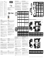
Elektrischer Anschluss Electrical connection
b Betreiben Sie den FTMg nur über eine Versorgung
mit sicherer Trennung vom Netz (PELV nach DIN VDE
0100-410, IEC 60364-4-41, HD 60364.4.41, EN
60079-14). Der Stromkreis muss potenzialfrei sein
(nicht geerdet).
b Montieren Sie den M12-Steckanschluss sorgfältig, um
die Schutzart IP67 sicherzustellen.
b Beachten Sie die Pin-Belegung (siehe unten).
b Der Durchusssensor besitzt drei Signalausgänge, die
gemäß Pin-Belegung verdrahtet werden können.
b Ethernet-Version: Der Sensor wird über die Ethernet-
Verbindung mit PoE versorgt. Montieren Sie den
M12-Steckeranschluss sorgfältig, um die Schutzart
IP67 sicherzustellen. Beachten Sie die Pin-Belegung.
b Only operate the FTMg via a supply with secure
disconnection from the circuit (PELV according to DIN
VDE 0100-410, IEC 60364-4-41, HD 60364.4.41, EN
60079-14). The power circuit must be potential free
(not grounded).
b Carefully mount the M12-plug connector, in order to
ensure the enclosure rating IP67.
b Observe the pin assignment (see below).
b The ow sensor has 3 signal outputs which can be
wired according to the pin-assignment.
b Ethernet-version: the sensor is supplied with PoE via
the Ethernet-Connection. Carefully mount the M12
Plug connector to accomplish the enclosure rating
IP67. Observe the pin-assignment.
1
2
3
4
5
Kontakt /
Contact
Kennzeich-
nung/
Identication
Aderfarbe/
Wire Color
Beschreibung/
Description
1 L+ braun /brown Versorgungsspannung /
Power supply
2 Q
A
weiß / white Analoger Stromausgang
4 ... 20 mA (skalierbar) /
Analogue current output 4 ...
20 mA (scalable)
3 M
blau / blue Masse, Bezugsmasse für Strom-
ausgang /
Mass, reference mass for current
output
4 C/Q
1
schwarz / black IO-Link-Kommunikation oder
digitaler Schaltausgang 1: NO/NC
programmierbar /
IO / IO-Link communication or digi-
tal output 1: NO/NC programmable
5 Q
2
grau / grey Digitaler Schaltausgang 2: NO/NC
programmierbar oder Stromaus-
gang B 4 … 20 mA, Frequenz oder
Pulsausgang / digital output 2 NO/
NC programmable or current output
B 4 … 20 mA, frequency or pulse
output
8
7
6
54
3
2
1
Kontakt/
Contact
RJ45 Farbe/
Color
Kennzeichnung/
Identication
10/100 Mbit
1 1 WH/OG TX (+) + POE TxData +
2 2 OG TX (-) + POE TxData -
3
3 WH/GN
RX (+) - POE RxData +
4
6 GN
RX (-) - POE RxData -
7
5 WH/BU
POE +
8 4 BU POE +
5 7 WH/BN POE -
6 8 BN POE -
Typ/
Type
(DN = Rohrdurchmesser /pipe
diameter)
3
Einlaufstrecke
/inlet path
1
Auslaufstecke
/outlet path
2
Ausdehnung/
extension
10 x DN 3 x DN
Verengung/red-
uction
10 x DN 3 x DN
90°Winkel/90°
elbow
20 x DN 5 x DN
Zwei 90° Winkel
auf einer Ebene/
Two 90° elbows
on one level
25 x DN 5 x DN
Zwei 90° Winkel
auf zwei Ebenen,
T-Stück/ Two 90°
elbows on two
levels, t-piece
30 x DN 5 x DN
Ventil, Schieber/
valve, slide
50 x DN 5 x DN
1
2
3
b Die richtige Montage ist relevant für die Messgenauig-
keit des FTMg.
b Die Strömungsrichtung des FTMg beachten.
b Den FTMg so weit entfernt wie möglich von
Strömungsstörungen platzieren (z. B. unterschiedliche
Rohrdurchmesser, Krümmungen, T-Stücke, Ventile
oder Schieber).
b Die vorgeschriebenen Längen der Ein- und Auslauf-
strecken beachten.
b Bei Gasen mit geringer Dichte längere Einlaufstrecken
wählen.
b The correct mounting is relevant for the measurement
accuracy of the FTMg.
b Observe the ow direction of the FTMg.
b Mount the FTMg as far as possible from ow distur-
bances (e.g. place different pipe diameters, curves,
T-pieces, valves or slides). Mount the FTMg before
valves or slides.
b Ensure that the path lenghts of the inlet and outlet
paths are correct.
b With light gases the inlet paths need to be extended.
95.2 3.75
78
3.06
45.5 1.79
18.5 0.73
109
4.29
85
3.35
22
0.87
107
4.21
22
0.87
M12x1
23
0.9121.8 0.86
18
0.71
18
0.71
Alle Maße in mm
All dimensions in mm (inch)
Typ/Type DN
1 2 3
FTMG-ISD15AXX 15 G 1/2 Ø 16,1 Ø 22
FTMG-ISD20AXX 20 G 3/4 Ø 21,7 Ø 27,5
FTMG-ISD25AXX 25 G 1 Ø 27,3 Ø 33,5
45.5 1.79
95.2 3.75
78
3.06
109
4.29
85
3.35
23
0.9121.8 0.86
22
0.87
22
0.87
13.4 0.53
18
0.71
18
0.71
M12x1
(X-coded)
Typ /Type DN
1 2 3
FTMG-ESD15AXX 15 G 1/2 Ø 16,1 Ø 22
FTMG-ESD15AXX 20 G 3/4 Ø 21,7 Ø 27,5
FTMG-ESD15AXX 25 G 1 Ø 27,3 Ø 33,5
Bei Montage/Demontage des Sensors muss die Mess-
gasleitung drucklos sein.
b Den Montageort leicht zugänglich und frei von Vibrati-
onen halten.
b Einen minimalen Freiraum von 150 mm zum FTMg
einhalten.
b Umgebungstemperatur beachten ("Technische
Daten").
b Das Messgas muss mindestens der Reinheits-
klasse 3:4:4 oder besser entsprechen, gemäß ISO
8573-1:2010.
b Das Messgas und die Umgebungsluft dürfen nicht
kondensieren.
b In Druckluftnetzwerken den FTMg nach dem Lufttrock-
ner montieren. Bei Fehlen eines Trockners den FTMg
nach dem Kondensatabscheider und geeigneten
Filtern installieren.
When installing/uninstalling the sensor the system must
be depressurised.
b The mounting location site shall be easily accessible
and free of vibration.
b A minimum clearance of 150 mm (4.72”) shall be
observed around the FTMg.
b The ambient temperature shall not exceed the speci-
ed limits.
b Air (medium) purity at the mounting location shall
comply to ISO 8573-1:2010, at least Class 3.4.4.
b The medium and the ambient conditions at the
mounting location shall be non-condensing.
b In compressed air networks, FTMg shall be installed
after the air dryer. In the absence of a dryer, FTMg
shall be installed after the condensate separator and
appropriate lters.
Einbaurichtung Installation position
Einbaubedingungen
Installation conditions
Wartung Maintenance
Der FTMg ist wartungsfrei. Wir empfehlen:
b Verschraubungen und Steckverbindungen sind in
regelmäßigen Abständen zu überprüfen
.
The FTMg is maintenance-free. We recommend doing the
following regularly:
b checking the screw connections and plug-in connec-
tions.
Rücksendung
Returns
Entsorgung Disposal
Entsorgen Sie Gerätekomponenten und Verpackungsma-
terialien entsprechend den einschlägigen landesspezi-
schen Abfallbehandlungs- und Entsorgungsvorschriften
des Anliefergebietes.
Dispose of device components and packaging materials
in compliance with applicable country-specic waste
treatment and disposal regulations of the region of use.
Säubern Sie ausgebaute Geräte vor der Rücksendung,
um unsere Mitarbeiter und die Umwelt vor Gefährdung
durch anhaftende Messstoffreste zu schützen. Eine
Überprüfung ausgefallener Geräte kann nur erfolgen,
wenn das vollständig ausgefüllte Rücksendeformular
vorliegt. Eine solche Erklärung beinhaltet alle Materia-
lien, welche mit dem Gerät in Berührung kamen, auch
solche, die zu Testzwecken, zum Betrieb oder zur
Reinigung eingesetzt wurden. Das Rücksendeformular ist
über unsere Internet-Adresse (www.sick.com) verfügbar.
Clean removed devices before returning them in order
to protect our employees and the environment from dan-
gers posed by residue from measured materials.
Faulty devices can only be examined when accompanied
by a completed return form. This form includes informati-
on about all materials which have come into contact with
the device, including those which were used for testing
purposes, operation, or cleaning. The return form is
available from our website (www.sick.com)
.
ENGLISH
DEUTSCH
Maßzeichnungen / Dimensional drawings
www.sick.com/FTMg
8024913//2019-10-02 ∙ Printed in Germany (GW/KE) ∙ 02-10-2019 ∙ 10/02 ∙ Subject to change without notice ∙ SICK AG ∙ Waldkirch ∙ Germany ∙ www.sick.com

Technische Daten
Technical Data
Oberer Signalpegel
3)
20,5 mA ... 21,5 mA
Digitalausgang
3)
≤ 100 mA pro Ausgang
Signalspannung
HIGH
3)
> Uv - 2 V
Signalspannung
LOW
3)
≤ 2 V
Induktive Last
3)
< 1 H
Kapazitive Last
3)
< 100 nF (2,5 nF bei IO-Link)
1)
Alle Anschlüsse haben Verpolschutz und sind überstromfest. Q1,
Q2 sowie Qa sind kurzschlussfest.
2)
Konguration des digitalen Ausgangs: PNP/NPN/Push-Pull.
3 )
Ausschließlich Industrie-Version.
)
Elektrische Anschlusswerte Ethernet -Version
Standardkommunikation
IEEE802.3 Clause 25 (100Ba-
seTx); 100Mbit/sec.
Standardversorgung
Power over Ethernet nach
IEEE802.3af
Leistungsklasse
Klasse 0; entspr. IEEE802.3af
Powered Device <13 W
Stromversorgungsmodus
Mode A und Mode B
Anschluss
M12x1 (female) 8 pin; X-codiert
Leistungsaufnahme
max. 5 W
Mechanik / Werkstoffe
Prozessanschluss G1 /2, G3 /4, G1
(entsprechend DIN ISO 228-1)
Medienberührte
Werkstoffe
Edelstahl 1.4305, PA6, Viton®,
Aluminium
Gehäusematerial PC+ABS, PA66+PA6I GF50, PC,
TPE,
Edelstahl 1.4301
Schutzart IP 65, IP 67 entspr. EN 60529
Gewicht G1/2 ca. 805 g
G3/4 ca. 755 g
G1 ca. 685 g
Umgebungsbedingungen
Umgebungstempera-
tur Betrieb
1)
–20 °C ... +60 °C
Umgebungstempera-
tur Lager
–40 °C ... +80 °C
Maximale relative
Luftfeuchtigkeit
≤ 90% RF nicht kondensierend
1)
Gemäß UL-Listing: Verschmutzungsgrad 3 (UL61010-1: 2012-05);
Luftfeuchtigkeit: 80 % bei Temperaturen bis zu 31 °C; Einsatzhöhe:
max 3.000 m ü.M.; nur für Indoor-Anwendungen.
Features
Measurement prin-
ciples
caliometric (ow, temperature)
piezoresistive (pressure)
Medium Compressed air (air quality
ISO 8573-1-:2010 [3:4:4])
Helium, Argon, Nitrogen, Car-
bondioxide
Nominal size DN15, DN20, DN25
Process temperature - 20 °C ... +60 °C
Process pressure 0 ... 16 bar
Communication
interface
IO-Link 1.1 COM3 (only Industri-
al version)
Ethernet (only Ethernet version)
OPC UA, MQTT und Webserver
Temparature
measurement
m
Pressure measure-
ment
m
User Interface 128 x 128 pixel per adjustment
OLED display turnable (90°
steps) and 4 buttons
Performance
Measuring range DN15: 5.3 ... 1060.3 l/min
DN20: 9.4 ... 1,884.9 l/min
DN25: 14.7 ... 2,945.2 l/min
(Standard measuring range acc.
ISO 8573-1:2010 [3:4:4])
DN15: 1,060.3 ... 1,590.4 l/min
DN20: 1,884.9 ... 2,827.4 l/min
DN25: 2,945.2 ... 4,417.9 l/min
(extended measuring range)
Minimum ow velo-
city
1)
0.5 m/s
Maximum ow
velocity
1)
150 m/s
Flow accuracy
1)
± 3 % of measured value
+ 0,3 % of full scale
(Standard measuring range acc.
ISO 8573-1:2010 [3:4:4])
± 8 % of measured value
+ 1 % of full scale
(extended measuring range)
Reproducibility ± 1.5 % of measured value
Response time (T90) < 0.3 s
Temperature
measurement
accuracy
± 2°C
Temperature repro-
ducibility
± 0.5 °C
Pressure measure-
ment:
Measurement accuracy:
± 1.5 % of measuring range
(10°C ... 30°C)
Non-Linearity:
≤ ± 0.5% of measuring range
(including temperature drift)
Reproducibility:
≤ ± 0.2% of measuring range
(BFSL acoording to IEC 61298-
2)
1)
Reference conditions according to DIN 1343: Atmospheric pressure
1,01325 bar abs. compressed air temperature 0°C
Electrical connection values for industrial version
Operating voltage U
v
1) 2)
17 V DC ... 30 V DC
Power consumption
< 12 W (24 V DC without output
load)
Initiliazation time
≤ 10 s
Protection class
III
Connection type
Round connector M12 x 1,5 -pin
(IO-Link version)
Output signa
3)
1 analogue output 4 ... 20 mA
(scalable);
1 PNP/NPN/Push-Pull-transistor
output
1 analogue output (scalable) or
PNP/NPN/Push-Pull-transistor
output (also congurable as
pulse/frequency output)
Output load
3)
4 mA ... 20 mA, max. 500 Ohm
(Uv > 15 V)
Lower signal level
3
3.5 mA ... 3.8 mA
Merkmale
Messprinzip Kalorimetrisch (Durchuss,
Temperatur)
Piezoresistiv (Druck)
Medium Druckluft (Luftqualität
ISO 8573-1-:2010 [3:4:4])
Helium, Argon, Stickstoff, Koh-
lendioxid
Nennweiten DN15, DN20, DN25
Prozesstemperatur - 20 °C ... +60 °C
Prozessdruck 0 ... 16 bar
Kommunikations-
Interface
IO-Link 1.1 COM3 (ausschließ-
lich Industrie-Version
Ethernet (ausschließlich
Ethernet-Version)
OPC UA, MQTT und Webserver
Temperaturmessung
m
Druckmessung
m
Display 128 x 128 Pixel per Einstellung
Drehbares OLED Display
(90° Drehungen) und 4 Tasten
Performance
Messbereich DN15: 5,3 ... 1.060,3 l/min
DN20: 9,4 ... 1.884,9 l/min
DN25: 14,7 ... 2.945,2 l/min
(Standardmessbereich nach
ISO 8573-1:2010 [3:4:4])
DN15: 1.060,3 ... 1.590,4 l/min
DN20: 1.884,9 ... 2.827,4 l/min
DN25: 2.945,2 ... 4.417,9 l/min
(erweiterter Messbereich)
Minimale Durchuss-
geschwindigkeit
1)
0,5 m/s
maximale Durchuss-
geschwindigkeit
1)
150 m/s
Genauigkeit des
Sensorelements
1)
± 3 % des Messwerts
+ 0,3 % des Messbereichend-
werts
(Standardmessbereich nach
ISO 8573-1:2010 [3:4:4])
± 8 % des Messwerts
+ 1 % des Messbereichend-
werts
(erweiterter Messbereich)
Reproduzierbarkeit ± 1,5 % des Messwerts
Ansprechzeit (T90) < 0,3 s
Messgenauigkeit
Temperatur
± 2°C
Reproduzierbarkeit
Temperatur
± 0,5 °C
Druckmessung: Messgenauigkeit:
≤ ± 1,5 % des Messbereichs
(10°C ... 30°C)
Nicht-Linearität:
± 0,5 % des Messbereichs
(inklusive Temperaturdrift)
Reproduzierbarkeit:
≤ ± 0,2% des Messbereichs
(BFSL entsprechend IEC 61298-
2)
1)
Referenzbedingungen nach DIN 1343: atmosphärischer Druck
1,01325 bar abs. Drucklufttemperatur 0°C
Elektrische Anschlusswerte Industrie-Version
Versorgungsspannung
U
v
1) 2)
17 V DC ... 30 V DC
Leistungsaufnahme
< 12 W (24 V DC ohne Aus-
gangslast)
Initialisierungszeit
≤ 10 s
Schutzklasse
III
Anschlussart
M12 Rundstecker x 1.5 - polig
(IO-Link Version)
Ausgangssignal
3)
1 Analogausgang 4 ... 20 mA
(skalierbar)
1 PNP / NPN / Push-Pull Transis-
torausgang
1 Analogausgang (skalierbar)
oder PNP / NPN / Push-Pull-
Transistorausgang (kongurier-
bar auch als Puls-/Frequenzaus-
gang)
Ausgangslast
3)
4 mA ... 20 mA, max. 500 Ohm
(Uv > 15 V)
Unterer Signalpegel
3)
3,5 mA ... 3,8 mA
Upper signal level
3)
20.5 mA ... 21.5 mA
Digital output
3
≤ 100 mA per output
Signal voltage HIGH
3
> Uv - 2 V
Signal voltage LOW
3
≤ 2 V
Inductive load
3
< 1 H
Capacitive load
3
< 100 nF (2.5 nF at IO-Link)
1)
All connections are reverse polarity protected. QA and QB are short-
circuit protected. Q1 and Q2 are short-circuit protected.
2)
Digital output conguration: PNP/NPN/Push-Pull.
3)
Only industrial version.
Electrical connection values for Ethernet version
Standard communication
IEEE802.3 Clause 25 (100Ba-
seTx); 100Mbit/sec.
Standard supply
Power over Ethernet acc.
IEEE802.3af
Performance class
Class 0; acc. IEEE802.3af Powe-
red Device <13 W
Power mode
Mode A and mode B
Connection type
M12x1 (female) 8 pin; X-coded
Power consumption
max. 5 W
Mechanics / Materials
Process connection G1 /2, G3 /4, G1
(according to DIN ISO 228-1)
Wetted parts Stainless steel 1.4305, PA6,
Viton®, Aluminium
Housing material PC+ABS, PA66+PA6I GF50, PC,
TPE, Stainless steel 1.4301
Protection class IP 65, IP 67 acc. EN 60529
Weight G1/2 approx. 805 g
G3/4 approx. 755 g
G1 approx. 685 g
Ambient data
Ambient operating
temperature
1)
–20 °C ... +60 °C
Ambient storage
temparature
–40 °C ... +80 °C
Maximum permissi-
ble relative humidity
≤ 90% RH non-condensing
1)
According to UL listing: degree of contamination 3 (UL61010-1:
2012-05); air humidity: 80 % at temperatures up to 31 °C; installati-
on height: max. 3,000 m above sea level; only for indoor applications.
Zubehör
Accessories
Nennweite /
Nominal size
Drehmoment /
torque
DN15 20 Nm
DN20 30 Nm
DN25
40 Nm
Kurzbeschreibung Typ Artikel-
nummer
Brief Description Type Part num-
ber
Ein-Auslaufrohre-Set für
FTMg (FTMG-xxx-25xxx)
mit Prozessanschluss
G1 in 1.4305
BEF-EL-G10D25-
FTMG
2111054 One discharge
pipe set for FTMg
(FTMG-xxx-25xxx)
with process
connection G1 in
1.4305
BEF-EL-G10D25-
FTMG
2111054
Ein-Auslaufrohre-Set für
FTMg (FTMG-xxx15xxx)
mit Prozessanschluss
G1/2 in 1.4305
BEF-EL-G12D15-
FTMG
2111050 One discharge
pipe set for FTMg
(FTMG-xxx15xxx)
with process
connection G1/2
in 1.4305
BEF-EL-G12D15-
FTMG
2111050
Ein-Auslaufrohre-Set für
FTMg (FTMG-xxx20xxx)
mit Prozessanschluss
G3/4 in 1.4305
BEF-EL-G34D20-
FTMG
2111052 One discharge
pipe set for FTMg
(FTMG-xxx20xxx)
with process
connection G3/4
in 1.4305
BEF-EL-G34D20-
FTMG
2111052
Ein-Auslaufrohre-Set für
FTMg (FTMG-xxx25xxx)
mit Prozessanschluss 1"
NPT in 1.4305
BEF-EL-N10D25-
FTMG
2111055 One discharge
pipe set for FTMg
(FTMG-xxx25xxx)
with process
connection 1" NPT
in 1.4305
BEF-EL-N10D25-
FTMG
2111055
Ein-Auslaufrohre-Set für
FTMg (FTMG-xxx15xxx)
mit Prozessanschluss
1/2" NPT in 1.4305
BEF-EL-N12D15-
FTMG
2111051 One discharge
pipe set for FTMg
(FTMG-xxx15xxx)
with process con-
nection 1/2" NPT
in 1.4305
BEF-EL-N12D15-
FTMG
2111051
Ein-Auslaufrohre-Set für
FTMg (FTMG-xxx20xxx)
mit Prozessanschluss
3/4" NPT in 1.4305
BEF-EL-N34D20-
FTMG
2111053 One discharge
pipe set for FTMg
(FTMG-xxx20xxx)
with process con-
nection 3/4" NPT
in 1.4305
BEF-EL-N34D20-
FTMG
2111053
-
 1
1
-
 2
2


in anderen Sprachen
- English: SICK FTMg
Verwandte Artikel
-
SICK DOSIC® Quickstart
-
-
-
-
-
-
-
-
-