
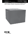
Type PST Model-9 Automatic Source Transfer Switchgear with iST
Control; Installation, Operation, and Maintenance Instructions
COOPER POWER
SERIES
Underground
Distribution Switchgear
MN285002EN
Effective April 2019
Supersedes April 2018

ii
INSTALLATION, OPERATION, AND MAINTENANCE INSTRUCTIONS MN285002EN April 2019
DISCLAIMER OF WARRANTIES AND LIMITATION OF LIABILITY
The information, recommendations, descriptions and safety notations in this document are based on Eaton Corporation’s
(“Eaton”) experience and judgment and may not cover all contingencies. If further information is required, an Eaton sales
office should be consulted. Sale of the product shown in this literature is subject to the terms and conditions outlined in
appropriate Eaton selling policies or other contractual agreement between Eaton and the purchaser.
THERE ARE NO UNDERSTANDINGS, AGREEMENTS, WARRANTIES, EXPRESSED OR IMPLIED, INCLUDING WARRANTIES
OF FITNESS FOR A PARTICULAR PURPOSE OR MERCHANTABILITY, OTHER THAN THOSE SPECIFICALLY SET OUT IN ANY
EXISTING CONTRACT BETWEEN THE PARTIES. ANY SUCH CONTRACT STATES THE ENTIRE OBLIGATION OF EATON. THE
CONTENTS OF THIS DOCUMENT SHALL NOT BECOME PART OF OR MODIFY ANY CONTRACT BETWEEN THE PARTIES.
In no event will Eaton be responsible to the purchaser or user in contract, in tort (including negligence), strict liability or
other-wise for any special, indirect, incidental or consequential damage or loss whatsoever, including but not limited to
damage or loss of use of equipment, plant or power system, cost of capital, loss of power, additional expenses in the use of
existing power facilities, or claims against the purchaser or user by its customers resulting from the use of the information,
recommendations and descriptions contained herein. The information contained in this manual is subject to change without
notice.

iii
INSTALLATION, OPERATION, AND MAINTENANCE INSTRUCTIONS MN285002EN April 2019
Contents
DISCLAIMER OF WARRANTIES AND LIMITATION OF LIABILITY ....................................II
SAFETY INFORMATION .................................................................... V
Safety instructions ...............................................................................v
PRODUCT INFORMATION ....................................................................1
Introduction ....................................................................................1
Acceptance and initial inspection ...................................................................1
Handling and storage .............................................................................1
Standards .....................................................................................1
Quality standards. . . . . . . . . . . . . . . . . . . . . . . . . . . . . . . . . . . . . . . . . . . . . . . . . . . . . . . . . . . . . . . . . . . . . . . . . . . . . . . . 1
PST MODEL-9 OVERALL DESCRIPTION ........................................................1
Vacuum interrupters .............................................................................2
Bushings ......................................................................................2
Standard cabinet features .........................................................................2
Interrupter duty cycle ............................................................................4
Switch test sequence ............................................................................4
Nameplate .....................................................................................4
Operating handles ...............................................................................4
Weight ........................................................................................4
RATINGS AND SPECIFICATIONS ..............................................................5
LOAD TRANSFER FUNCTIONALITY ............................................................5
iST control operation ............................................................................5
Operation of interval timer ........................................................................9
CI switch .....................................................................................10
Operating modes ..............................................................................10
CI operating sequences .........................................................................10
Manual operation of CI switches ...................................................................11
OVERCURRENT PROTECTION FUNCTIONALITY ................................................11
Vacuum fault interrupters (VFI) ....................................................................12
Manual VFI operation ............................................................................12
Opening VFI switches ...........................................................................13
Resetting VFI switches ..........................................................................13
Closing VFI switches ............................................................................13
INSTALLATION PROCEDURES ...............................................................13
Initial mechanical operation check ..................................................................14
Initial electrical operation check ....................................................................15
Initial iST control operation check ..................................................................16

iv
INSTALLATION, OPERATION, AND MAINTENANCE INSTRUCTIONS MN285002EN April 2019
MAINTENANCE ...........................................................................17
Maintenance inspection procedure .................................................................17
Internal inspection and repair .....................................................................18
Insulating fluid maintenance ......................................................................18
Frequency of maintenance .......................................................................19
Types of fluid samples ...........................................................................19
Fluid sampling guidelines ........................................................................19
Fluid fill guidelines ..............................................................................20
Fluid testing ...................................................................................21
Dissolved gas analysis ...........................................................................21
TESTING ................................................................................22
High-potential withstand testing of vacuum interrupters ................................................22
REPLACEMENT PARTS .....................................................................22

Type PST Model-9 Automatic Source Transfer Switchgear with iST Control
Safety for life
Eaton meets or exceeds all applicable industry standards relating to product safety in its Cooper Power™ series products.
We actively promote safe practices in the use and maintenance of our products through our service literature, instructional
training programs, and the continuous efforts of all Eaton employees involved in product design, manufacture, marketing, and
service.
We strongly urge that you always follow all locally-approved safety procedures and safety instructions when working around
high-voltage lines and equipment, and support our “Safety For Life” mission.
Safety information
The instructions in this manual are not intended as a
substitute for proper training or adequate experience in the
safe operation of the equipment described. Only competent
technicians who are familiar with this equipment should
install, operate, and service it.
A competent technician has these qualifications:
Is thoroughly familiar with these instructions.
Is trained in industry-accepted high- and low-voltage safe
operating practices and procedures.
Is trained and authorized to energize, de-energize, clear,
and ground power distribution equipment.
Is trained in the care and use of protective equipment
such as arc flash clothing, safety glasses, face shield,
hard hat, rubber gloves, clampstick, hotstick, etc.
Following is important safety information. For safe
installation and operation of this equipment, be sure to read
and understand all cautions and warnings.
Hazard Statement Definitions
This manual may contain four types of hazard statements:
DANGER
Indicates an imminently hazardous situation which, if
not avoided, will result in death or serious injury.
WARNING
Indicates a potentially hazardous situation which, if not
avoided, could result in death or serious injury.
CAUTION
Indicates a potentially hazardous situation which, if not
avoided, may result in minor or moderate injury.
NOTICE
Indicates a potentially hazardous situation which, if not
avoided, may result in equipment damage only.
Safety instructions
Following are general caution and warning statements that
apply to this equipment. Additional statements, related to
specific tasks and procedures, are located throughout the
manual.
DANGER
Hazardous voltage. Contact with hazardous voltage will
cause death or severe personal injury. Follow all locally-
approved safety procedures when working around high-
and low-voltage lines and equipment.
G103.3
WARNING
Before installing, operating, maintaining, or testing this
equipment, carefully read and understand the contents
of this manual. Improper operation, handling, or
maintenance can result in death, severe personal injury,
and equipment damage.
G101.0
WARNING
This equipment is not intended to protect human
life. Follow all locally-approved procedures and safety
practices when installing or operating this equipment.
Failure to comply can result in death, severe personal
injury, and equipment damage.
G102.1
WARNING
Power distribution and transmission equipment must
be properly selected for the intended application. It
must be installed and serviced by competent personnel
who have been trained and understand proper safety
procedures. These instructions are written for such
personnel and are not a substitute for adequate training
and experience in safety procedures. Failure to properly
select, install, or maintain power distribution and
transmission equipment can result in death, severe
personal injury, and equipment damage.
G122.2
!
SAFETY
FOR LIFE
!
SAFETY
FOR LIFE
v
INSTALLATION, OPERATION, AND MAINTENANCE INSTRUCTIONS MN285002EN April 2019

Type PST Model-9 Automatic Source Transfer Switchgear with iST Control
This page is intentionally left blank.
vi
INSTALLATION, OPERATION, AND MAINTENANCE INSTRUCTIONS MN285002EN April 2019

Type PST Model-9 Automatic Source Transfer Switchgear with iST Control
Product information
Introduction
Service Information MN285002EN provides installation
instructions, operation information, maintenance
procedures, and testing information for Eaton's Cooper
Power™ series Type PST Model-9 Underground Distribution
Automatic Source Transfer Switchgear with iST Control.
Before installing and operating this control, carefully read
and understand the contents of this manual.
For additional information, refer to the following applicable
service information bulletins:
S275-10-1 Type CI Three-Phase Fault Interrupters
Installation and Operation Instructions
MN285006EN Type VFI, Fluid Insulated, Vacuum Fault
Interrupter; Installation, Operation, and Maintenance
Instructions
Read this manual first
Read and understand the contents of this manual and follow
all locally approved procedures and safety practices before
installing or operating this equipment.
Additional information
These instructions cannot cover all details or variations
in the equipment, procedures, or process described, nor
provide directions for meeting every possible contingency
during installation, operation, or maintenance. For additional
information, please contact your Eaton representative.
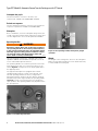
Acceptance and initial inspection
The PST switchgear is completely assembled, tested, and
inspected at the factory. The switchgear is filled to the
correct level with insulating fluid. It is in good condition
when accepted by the freight carrier for shipment.
1. Upon receipt, inspect the unit thoroughly for damage
and loss of parts or fluid incurred during shipment.
If damage or loss is discovered, file a claim with the
carrier immediately.
2. Check for fluid leakage.
Handling and storage
The switchgear should remain on its shipping pallet until it is
installed. When handling the switchgear, always use a fork
truck that has adequate lifting capacity and forks that extend
the entire length of the pallet. Improper handling can cause
damage to the switchgear.
If the switchgear is to be stored for any appreciable time
before installation, provide a clean, dry storage area.
Be careful during handling and storage to minimize the
possibility of mechanical damage. Do not stack other
material on the switchgear.
Standards
PST Model-9 Underground Distribution Switchgear products
are designed and tested in accordance with standards: IEEE
Std C57.12.28™-2005 and IEEE Std 386™-2006.
Quality standards
ISO 9001 Certified Quality Management System.
PST Model-9 overall description
Type PST Model-9 Automatic Source Transfer Switchgear
provides both loss-of-source health and overcurrent
protection for critical loads for 15, 25, and 35 kV
underground systems.
PST Model-9 units are self-contained, steel constructed
underground distribution enclosures containing mineral oil
or Envirotemp™ 200™ as a dielectric insulating medium.
They are shipped fully assembled and filled with insulating
fluid. PST Model-9 switchgear is designed for outdoor
mounting on a concrete pad. Power is fed to, and from, the
switchgear from underground through openings in the pad.
Deadfront construction minimizes the high voltage safety
hazards for both the operator and the general public.
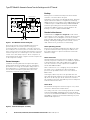
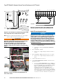
Loss-of-source health protection functionality is provided
by an iST control system and two three-phase Type CI
motor-operated, source-side vacuum interrupter switches
(Figure 1).
Eaton's Cooper Power series iST control monitors the
preferred and alternate line voltages and provides the timing
and control logic required to perform the automatic load
transfer in the event of a source health loss. The control
commands the operations of the two Type CI vacuum
interrupter switches during auto transfer. Manually operated
levers enable manual trip and close of source-side CI
interrupter switches during power outages. Operational
power (120 Vac) for the transfer control and vacuum
switches is derived from system line levels via internally
mounted potential transformers; no external source of
power is required.
Eaton's Cooper Power series VFI Interrupters and iST control
provide independent overcurrent protection of the two
PST taps. Both taps are independently served by separate
controls commanding the operations of a dedicated VFI
vacuum fault interrupter on each tap (Figure 1).
1
INSTALLATION, OPERATION, AND MAINTENANCE INSTRUCTIONS MN285002EN April 2019

Type PST Model-9 Automatic Source Transfer Switchgear with iST Control
Control
Control
PTs
PTs
Fault Block Signal
Overcurrent
Protection
Overcurrent
Protection
iST-921
Voltage Input
Figure 1. PST Model-9 functional diagram
Overcurrent sensing, timing, and tripping functions are
performed by the iST control system. Sensing CTs,
mounted internally on each phase of the tap connections,
are used by the iST control system to monitor load current.
If the current monitored is greater than the phase or ground
minimum trip level, the control begins a user selected time-
current curve (TCC) delay sequence. At the completion of
the programmed TCC delay, a signal is issued to trip the VFI
on the respective load tap.
Vacuum interrupters
Load-break switching and fault interruption takes place
within sealed vacuum interrupters. Vacuum interrupters
provide fast, low energy arc interruption and produce no
arcing by-products to contaminate the insulating fluid.
Use of vacuum interruption significantly reduces the
maintenance required of this equipment.
Figure 2. Vacuum interrupter assembly
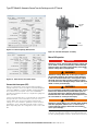
Bushings
Bushings are mounted horizontally in-line and located a
minimum of 24 inches above the pad.
Depending on the rating of the PST Model-9 unit, bushings
may be furnished in different configurations and ratings.
200A interfaces are provided as either 200A bushing wells
or 200A one-piece loadbreak bushings. 600A deadbreak
aluminum type bushings are furnished for PST Model-9
units rated for 600A continuous current operation. All
bushings conform to IEEE Std 386™-2006.
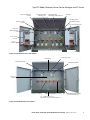
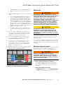
Standard cabinet features
Standard features (Figure 3 and Figure 4) include a fluid
level indicator on each front plate, automatic pressure-relief
valve, operation one-line diagrams on the doors, fluid fill
plug, fluid drain and sampler, and a standoff bracket for each
bushing. Standard grounding provisions include a 1/2-13
UNC stainless steel ground nut for each bushing.
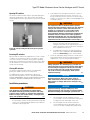
Cabinet padlocking provisions
Provisions are included for padlocking the cabinet in order
to prevent unauthorized door opening. The cabinet must
be locked at all times to prevent accidental contact with
hazardous voltage.
Cabinet construction
Type PST Model-9 switchgear features deadfront, tamper-
resistant, low-profile construction. It is suitable for operation
in demanding indoor and outdoor applications. Cabinets
meet the enclosure security requirements of IEEE Std
C57.12.28™-2005 standard.
Tank construction is of 7- or 10-gauge steel, and cabinets
are made of 12- or 13-gauge steel. Recessed lifting
provisions are provided at each corner of the tank for a
balanced lift.
Side-hinged, cabinet style doors are provided with door
stays and fitted with stainless steel hinges. Both source and
tap doors can be fully open at the same time. Each door
has a floating lock pocket with padlock provisions and penta-
head silicon bronze door bolt.
Cabinet finish
PST Model-9 switchgear is finished in a green color, which
conforms to Munsell 7GY 3.29/1.5 Green.
The coating conforms to the following specifications: IEEE
Std C57.12.28™-2005, ASTM B117 24-hour 5% salt spray
corrosion test, ASTM D2247 1000-hour humidity test, ASTM
G53 500-hour ultraviolet accelerated weathering test, and
ASTM D2794 impact test.
2
INSTALLATION, OPERATION, AND MAINTENANCE INSTRUCTIONS MN285002EN April 2019

Type PST Model-9 Automatic Source Transfer Switchgear with iST Control
Nameplate
Potential Transformer Dead-break Disconnect Switch
Source 2 Bushings
Source 1
Bushings
iST 921 Control
Enclosure
Interrupting Switch
Manual Spring Charge Operator
CI Switch S2 Manual
Operating Lever
CI Switch S1 Status
Indicator
CI Switch S1
Manual Operating
Lever
Interrupting Switch
Spring Charge Indicator
CI Switch S1 Operation
Counter
iST 901 Control Enclosure
Figure 3. PST Model-9 source-side features
Fluid Level
Indicator
Fluid Drain Plug and Sampler
(located behind the sill)
Tap 2 Bushings
Tap 1 Bushings
VFI Operating Handle
VFI Operating Handle
Fluid Fill Plug
Pressure Relief Valve
1/2 - 13UNC Stainless Steel
Ground Nut - Typ. (located behind the sill)
Figure 4. PST Model-9 tap-side features
3
INSTALLATION, OPERATION, AND MAINTENANCE INSTRUCTIONS MN285002EN April 2019

Type PST Model-9 Automatic Source Transfer Switchgear with iST Control
Interrupter duty cycle
The VFI mechanism conforms to the duty cycle
requirements of IEEE Std C37.60™-2003 standard.
Switch test sequence
The VFI operating mechanism conforms to the switch test
sequence requirements of IEEE Std C37.60™-2003.
Nameplate
Prior to installation, check the nameplate ratings. Verify the
overall current and voltage ratings, transformer ratings, and
one-line diagrams are correct for the planned installation.
Operating handles
WARNING
Hazardous voltage. Never rely on the open position of
the operating handle or the contact position indicator;
it does not ensure that the line is de-energized. Follow
all locally approved safety practices. Failure to comply
can result in contact with high voltage, which will
cause death or severe personal injury.
G123.1
Type PST Model-9 switchgear is equipped with hotstick-
operable loadbreak switch handles for operation of the CI
source-side and VFI tap-side switches.
The operating handles of CI switches provide incremental
travel between the trip, close, and reset positions of the
switch (Figure 5). CI trip-reset levers may be padlocked in
the tripped position.
The Type VFI interrupters are equipped with hotstick-
operable handles that are located on the tap-side of the
unit. VFI operating handles are factory configured for
ganged three-phase operation (all three phases operated
simultaneously with a single handle). The operating handle
(Figure 6) provides convenient push-to-close and pull-to-
open operation. VFI operating handles may be padlocked in
the open position.
Figure 5. CI switch trip-reset lever
Figure 6. VFI operating handle, three-phase ganged
operation
Weight
The weight of the switchgear is shown on the nameplate.
Make sure that lifting equipment used is rated sufficiently
to safely handle the switchgear.
4
INSTALLATION, OPERATION, AND MAINTENANCE INSTRUCTIONS MN285002EN April 2019

Type PST Model-9 Automatic Source Transfer Switchgear with iST Control
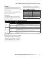
Ratings and specifications
Table 1. Electrical ratings PST Model-9 transfer switchgear
Description 15 kV 25 kV 35 kV
Maximum Design Voltage, kV 15.5 27 38
BIL, kV 95 125 150
1-Minute Withstand Voltage (60 Hz) Interrupter and Terminators, kV 35 40 50
Continuous Current (max), A 600 600 600
Interrupting Current (sym./asym.), kA 12/20 12/20 12/20
Momentary Current 10 cycles (asym.), kA 20 20 25
1-Second Withstand Current (sym.), kA 12 12 12
Making Current (sym.), kA 12 12 12
Transformer Magnetizing Interrupting Current, A 21 21 21
Cable Charging Interrupting Current, A 10 25 40
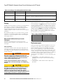
Table 2. Interrupting duty cycle
Percent of Interrupting Current Rating Number of Operations
15 – 20 88
45 – 55 112
90 – 100 32
Total 232
Table 3. Switching and transfer times
Direction of
Transfer Transition
Type of Return
(Cycles)
First Interrupter
Reaction Time*
Cycles
Transition
Time**
Cycles
Preferred to Alternate Non-Parallel 2.0 to 3.0 5.0 to 6.0
Alternate to Preferred Non-Parallel 2.0 to 3.0 5.0 to 6.0
Alternate to Preferred Parallel 5.0 to 6.0 2.0 to 3.0
* Time from expiration of time delay to first opening (or closing) of high-
voltage interrupter. Add about 1 cycle to values shown to allow for iST
control relay time.
** Time load tap is disconnected or parallel, dependant upon transition
used.
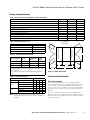
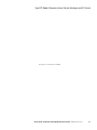
Table 4. Overall dimensions
Unit Description Dimensions (in)
Overall rating Bushing Rating Source/Tap A B C D
15/25 kV
600 A/200 A 95 70 36 16
600 A/600 A 101 70 36 22
200 A/200 A 89 70 30 16
35 kV
600 A/200 A 103 70 40 20
600 A/600 A 109 70 40 26
200 A/200 A 97 70 34 20
ote:N Dimensional information is for reference only,
actual dimensions may vary depending on features
included.
30" A 30"
DEC
B
Tap Cabinet
Source Cabinet
All Cabinets
48" High
iST 621/921
iST 901
Figure 7. Cabinet dimensions
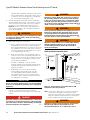
Load transfer functionality
iST control operation
The iST control monitors the source voltage and feeder
current and provides the programmable timing and control
logic required to perform the automatic load transfer in the
event of a loss of source health. The control commands the
operations of the two Type CI source switches during auto
transfer.
The source health is determined by seven independent
parameters for source health. Each has a settable threshold
and time delay. Any combination can be enabled to declare
an unhealthy source:
5
INSTALLATION, OPERATION, AND MAINTENANCE INSTRUCTIONS MN285002EN April 2019

Type PST Model-9 Automatic Source Transfer Switchgear with iST Control
Figure 8. Source health menu
Two levels of phase-ground undervoltage (27)
Positive sequence undervoltage (27P)
Two levels of underfrequency (81U)
Two levels of overfrequency (81O)
Four independent parameters declare Source Restoration.
Any combination can be enabled to declare a restored
source:
Minimum phase-ground voltage (59)
Minimum positive sequence voltage (59P)
Minimum frequency (81U)
Maximum frequency (81O)
The face of the control (Figure 12) provides visual indication
of the status of each Cl switch, control settings, and manual
operation capabilities. The transfer operation is programmed
on the control panel; digital timer settings and switch
settings permit complete program flexibility to coordinate
with other system operating parameters.
The control requires 120 Vac, 50/60 Hz, 500 VA to operate
the transfer switches. Quiescent power dissipation at 120
Vac is 18 watts. No external source of power is required for
the control as the 120 Vac power requirement is supplied by
the B-Phase (Source I) and Y-Phase (Source II) inputs from
the internally mounted potential transformers.
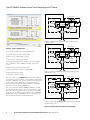
Control
Control
PTs
PTs
Fault Block Signal
Overcurrent
Protection
Overcurrent
Protection
iST-921
Voltage Input
Control
Control
PTs
PTs
Fault Block Signal
Overcurrent
Protection
Overcurrent
Protection
iST-921
Voltage Input
Control
Control
PTs
PTs
Fault Block Signal
Overcurrent
Protection
Overcurrent
Protection
iST-921
Voltage Input
Sequence 1: Model-9 unit connected to preferred source during normal
operating conditions
Sequence 2: Model-9 unit switched to alternate voltage source after loss of
preferred voltage source
Sequence 3: Model-9 unit switched back to preferred source after restoration
of preferred voltage source
Figure 9. PST Model-9 load transfer functionality
6
INSTALLATION, OPERATION, AND MAINTENANCE INSTRUCTIONS MN285002EN April 2019

Type PST Model-9 Automatic Source Transfer Switchgear with iST Control
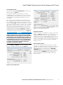
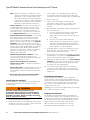
Preferred mode operation
The following is a typical Preferred Mode automatic load-
transfer sequence (Figure 8):
The load is transferred to the alternate source, after
completing a preset time delay, when one or more of the
health parameters of the preferred source falls outside of
the programmed settings and the alternate source is of
good health.
The load is then transferred back to the preferred source,
after completing a preset time delay, when the preferred
source again becomes healthy. The return transfer can be
either non-parallel (NP) in which the alternate-source switch
opens before the preferred-source switch closes, or parallel
(P) in which the preferred-source switch closes before the
alternate-switch opens. With parallel return, the second
outage is eliminated; however, the Sync Check function on
the ProView Sync Check Tab (see Figure 9) is enabled to
ensure both sources are in phase. The return transfer mode
is selected by setting the Source Preference on, Figure 10.
NOTICE
Equipment misoperation. Source I and Source II high
voltage switches can be paralleled by manual operation
of the handles on the switch front plate, regardless of
the Source Preference and Transfer Settings in the relay
control. Make sure both sources are in synchronism if
a manual parallel operation is to be performed. Failure
to comply can result in misoperation (unintended
operation) and equipment damage.
T382.0
Either Source I or Source II can be selected as the
preferred (PREF 1 or PREF II) source by setting the Source
Preference-and-Return Mode. Reference Figure 11.
Figure 10. Sync check menu
Figure 11. Source preference menu
No preference operation
When either source is acceptable for continuous critical load
supply, see Figure 11. Upon loss of source health on Source
I and after a preset time delay, the load is automatically
transferred to Source II if normal voltage is present on Source
ll. However, the load is not transferred back when Source I
voltage is restored, but remains on Source II indefinitely, until
a loss of source health on Source II initiates an automatic
transfer to Source I.
Hold on alternate operation
For some loss-of-voltage protection schemes, it may be
preferable to inhibit return to the preferred source from the
alternate source upon restoration of the preferred source
voltage. By placing Control Mode into the HOLD ON
ALTERNATE position, manual operation of the switches is
required to transfer back to the preferred source. Moving
Control Mode to the NORMAL position during return
sequence inhibition will cause immediate return to the
Preferred Source.
7
INSTALLATION, OPERATION, AND MAINTENANCE INSTRUCTIONS MN285002EN April 2019

Type PST Model-9 Automatic Source Transfer Switchgear with iST Control
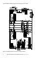
CONNECTOR - 14 COND.
IST-901 CONTROL
VFI2
CONNECTOR-19 COND.
IST-921 CONTROL RC2
CONNECTOR-8 COND.
IST-921 CONTROL
RC1
Figure 12. PST Model-9 automatic source transfer switchgear schematic
8
INSTALLATION, OPERATION, AND MAINTENANCE INSTRUCTIONS MN285002EN April 2019

Type PST Model-9 Automatic Source Transfer Switchgear with iST Control
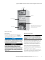
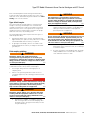
iST relay
Six PT fuses
Battery backup
GFCI Convenience
outlet
Heater
Optional auxiliary switch terminal strip for user
monitoring of switch status, independent of
relay optional. (Not shown.)
Figure 13. iST control
Manual operation
Each switch can be independently opened and closed
manually by setting Operation Selector to MANUAL and
operating MANUAL OPER. SOURCE S1 and MANUAL
OPER. SOURCE S2 as required.
NOTICE
Parallel connection of sources is possible when manually
closing CI interrupters. If parallel connection of sources is
not desired, do not operate the trip-reset levers of both
CI interrupters into the closed position.
T275.0
IMPORTANT
If Control Mode is placed in “AUTO” mode, the iST
control will place the high-voltage Type CI transfer
switches into the configuration that is currently
selected by the Source Preference. This may result in an
unintended transfer. Make sure the desired state of the
high-voltage Type CI transfer switches match the setting
of Source Preference before returning Control Mode to
“AUTO” mode.
Operation of interval timer
IMPORTANT
Put control in manual mode prior to changing timer
setting. There is no loss of voltage protection when in
manual mode. Failure to comply can cause unintended
operation.
The iST control features multiple digital timers with
automatic reset. Each of the seven available source health
parameters has a user programmable time delay setting
from 0-3600 seconds. When returning from alternate,
each of the (four) 4 restoration parameters has a user
programmable time delay setting from 30-3600 seconds.
The time-delay setting for preferred-to-alternate-source
transfer must be long enough to allow discrimination
between permanent loss of voltage and temporary loss
of voltage due to transient effects or reclosing intervals of
backup protective reclosers or breakers.
The time delay for return from alternate to preferred source
upon restoration of preferred-source voltage should be set
for an interval long enough to assure that service on the
preferred source has been permanently restored.
9
INSTALLATION, OPERATION, AND MAINTENANCE INSTRUCTIONS MN285002EN April 2019

Type PST Model-9 Automatic Source Transfer Switchgear with iST Control
When the iST control is programmed to operate in the
no-preference mode, there are no preferred or alternate
sources. Time-delay intervals for transfer from Source I to
Source ll are governed by the left preferred-to-alternate
timer and for transfer from Source ll to Source I by the right
alternate-to-preferred timer.
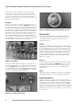
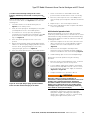
CI switch
Eaton's Cooper Power series Type CI three-phase motor-
operated source transfer switches (Figure 14) employ long-
life vacuum interrupters. The vacuum interrupter contacts
are opened and closed by a mechanism that releases stored
spring energy. The separate opening and closing springs are
automatically charged by a 120Vac motor. The load transfer
interrupter switches are electrically operated and receive
trip or close signals from the iST control. Solenoids receive
the command signals and release the charged springs to
effect a quick close operation of the vacuum contacts, and
Flux-Shift Trippers (FST) receive the command to release the
charged springs to effect a quick open operation.
Figure 14. CI switches
CI switches can be manually operated for test purposes or
if operating power is lost. A hotstick operable, external trip-
reset lever (Figure 15) allows switches to be opened and
closed manually. An external push-pull operator is provided
for manually charging the springs (Figure 16). The push-pull
operator is easily operated with a hotstick.
Figure 15. CI switch trip-reset lever
Figure 16. Manual push-pull spring charging operator
Operating modes
The Cl switches can be tripped automatically, electrically,
or manually operated; they can be closed electrically or
manually provided the springs are charged. CI switch
operating modes are:
Automatic
The CI Switch Trip-Reset Levers (S1 and S2) must be in the
RESET position for automatic load transfer control operation
to occur. Tripping and closing of the CI transfer switches is
initiated by a signal from the iST control. An opening signal
briefly energizes the opening FST and releases a latch that
trips the opening springs. A closing signal energizes the
closing solenoid and trips the closing spring. Closing is not
permitted until the limit switch closes to indicate that the
springs are charged.
Electrical
Non-automated opening and closing are initiated by operation
of the membrane pushbutton (Figure 26) on the iST control
front panel. Non-automated electrical opening and closing
is permitted only when the iST control is operating in the
manual mode.
Manual
Tripping and closing are initiated by operation of the manual trip-
reset handles located on the source-side pad-mounted tank.
CI operating sequences
When the interrupter contacts are open and the 120Vac
supply to the spring charging motor is energized, the spring
charging motor will charge the closing and opening springs.
The CI Trip-Reset Levers (S1 and S2) must be in the RESET
position for this operation to occur. Upon receipt of a closing
signal, a solenoid-operated latch releases the closing spring
which drives the three vacuum interrupter contacts to their
closed position.
10
INSTALLATION, OPERATION, AND MAINTENANCE INSTRUCTIONS MN285002EN April 2019

Type PST Model-9 Automatic Source Transfer Switchgear with iST Control
As the contacts are closed, the closing spring energy is
discharged while the opening spring remains charged and
latched. Upon receipt of an opening signal, the FST releases
the opening-spring latch, and the contacts of all three
vacuum interrupters are simultaneously driven to their open
position as the opening spring discharges. Immediately after
the contacts reach full open, the spring charging cycle is
repeated as the spring charging motor runs to recharge the
springs. Recharging is completed in about 20 seconds, and
both closing and opening springs are then latched and ready
for future operations. Should the 120V motor power be lost
while the interrupter contacts are open but after the springs
have been charged, one contact closing operation can still
be achieved through use of the trip-close handle on the
mechanism tank. Likewise, after the interrupter has been
closed, energy for one trip operation remains stored in the
mechanism.
Manual operation of CI switches
With its manual spring-charging capability, the Cl switches
can be operated without the presence of the low-voltage
motor supply from the iST control.
DANGER
Hazardous voltage. Contact with hazardous voltage will
cause death or severe personal injury. Follow all locally
approved safety procedures when working around high-
and low-voltage lines and equipment.
G103.3
WARNING
Hazardous voltage. Never rely on the open position of the
operating handle or the contact position indicator; it does
not ensure that the line is de-energized. Follow all locally
approved safety practices. Failure to comply can result in
contact with high voltage, which will cause death or severe
personal injury.
G123.1
NOTICE
Equipment misoperation. Source I and Source II high
voltage switches can be paralleled by manual operation
of the handles on the switch front place, regardless of
the Source Preference and Transfer Settings in the relay
control. Make sure both sources are in synchronism if
a manual parallel operation is to be performed. Failure
to comply can result in misoperation (unintended
operation) and equipment damage.
T382.0
Manual closing of CI switch
NOTICE
Parallel connection of sources is possible when
manually closing CI interrupters. If parallel connection
of sources is not desired, do not operate the trip-reset
levers of both CI interrupters into the closed position.
T275.0
Manual closing during loss of 120 Vac supply can be
accomplished by using the following procedure:
1. Put the iST control system into MANUAL mode to
eliminate any unexpected opening and closing of the
CI source switches when Vac supply is restored.
2. Observe the CI switch spring status indicator. If the
indicator shows the springs are discharged, proceed
with Step 3. If the indicator shows springs are charged,
proceed to Step 5.
3. Move the CI Transfer Switch Trip-Reset lever to the TRIP
position and then to the RESET position.
4. Using a hotstick stick, pull the spring charging handle
approximately 30 times or until the spring charging
indicator switches from the white, "spring discharged,"
to the yellow, "springs charged," position.
5. Move the Trip-Reset lever to CLOSE. Interrupter
contacts will close and handle will spring back to the
RESET Position.
Manual tripping of CI switch
1. Move the CI switch lever to the TRIP position. This
action will release a trip in the operating mechanism
that allows the charging springs to drive the contacts
to their open position. The trip-reset lever will remain in
the TRIP position.
The interrupter can not be closed by the iST control while
the Trip-Reset Lever is in the TRIP position.
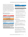
For additional information regarding the operation and
adjustment of Type CI Vacuum Interrupters Switches,
refer to Service Information Bulletin S275-10-1, Type CI
Three-Phase Fault Interrupters Installation and Operation
Instructions.
Overcurrent protection functionality
For dual feeder applications, the iST-921 relay provides
overcurrent protection for feeder 1, and the iST-901 relay
provides overcurrent protection for feeder 2. A Fault-block
function is included to enable or disable automatic transfer
during the overcurrent (OC) event.
When enabled in the iST-921/iST-901 two feeder application,
fault block prevents an automatic transfer while either OC
element is picked up. When the OC element drops out
after a trip, automatic operations resume for the feeder that
remains in service.
11
INSTALLATION, OPERATION, AND MAINTENANCE INSTRUCTIONS MN285002EN April 2019

Type PST Model-9 Automatic Source Transfer Switchgear with iST Control
Figure 17. Cold load pickup (CLPU) menu
Figure 18. Time-current curve (TCC) menu
Vacuum fault interrupters (VFI)
Eaton's Cooper Power series vacuum fault interrupters
(VFI) provide fault current interruption and load make/break
switching capabilities. Hotstick-operable operating handles
are located on the front plate of the unit. Standard VFI
operating mechanisms are factory configured for ganged 3
phase operation.
Current sensing transformers, located inside the switchgear
tank, provide line current information to the iST control
system. When line current exceeds the minimum trip
setting, the control initiates a signal that causes the VFI to
interrupt the circuit. Interruption may be single- or three-
phase depending upon the configuration of the control and
VFI.
Flux Shift
Tripper
Vacuum
Interrupter
Figure 19. Vacuum interrupter assembly
Manual VFI operation
DANGER
Hazardous voltage. Contact with hazardous voltage will
cause death or severe personal injury. Follow all locally
approved safety procedures when working around high-
and low-voltage lines and equipment.
G103.3
WARNING
Hazardous voltage. Never rely on the open position of
the operating handle or the contact position indicator;
it does not ensure that the line is de-energized. Follow
all locally approved safety practices. Failure to comply
can result in contact with high voltage, which will cause
death or severe personal injury.
G123.1
WARNING
Do not operate this equipment if energized parts are not
immersed in dielectric fluid. Operation when parts are
not properly immersed in dielectric fluid may result in
internal flashovers that will damage the equipment and
can cause death or severe personal injury.
G104.4
WARNING
Hazardous voltage. Always use a hotstick when working
with this equipment. Failure to do so could result in
contact with high voltage, which will cause death or
severe personal injury.
G108A.0
The VFI operating handles (Figure 4 and Figure 19) are
located on the tap-side front plate of the PST Model-9 unit.
The VFI operating handles must be operated with a hotstick.
12
INSTALLATION, OPERATION, AND MAINTENANCE INSTRUCTIONS MN285002EN April 2019

Type PST Model-9 Automatic Source Transfer Switchgear with iST Control
Opening VFI switches
The Vacuum Fault Interrupter (VFI) is opened by pulling the
operation handle down to the open position. The handle
may be padlocked in the open position to prevent accidental
closure.
Figure 20. VFI operating handle, three-phase ganged
operation
Resetting VFI switches
After the VFI mechanism has tripped as the result of a fault
condition, the mechanism must be reset before it can be
closed. To reset the mechanism, firmly pull the operating
handle down toward the ground until the latch resets. After
the latch has been successfully reset, the VFI mechanism
can be closed normally.
Closing VFI switches
The Vacuum Fault Interrupter (VFI) is closed by briskly
pushing the handle up into the closed position.
For additional information regarding the operation of
Vacuum Fault Interrupters, refer to: Service Information
Bulletin MN285006EN, Type VFI, Fluid-Insulated Switchgear;
Installation, Operation, and Maintenance Instructions.
Installation procedures
WARNING
This equipment is not intended to protect human
life. Follow all locally approved procedures and safety
practices when installing or operating this equipment.
Failure to comply can result in death, severe personal
injury, and equipment damage.
G102.1
1. Check fluid level. Make sure the fluid in switchgear tank
is at the proper level by checking the fluid level indicator
on the source-side and tap-side panels; both indicators
should be at the proper level.
2. Test fluid dielectric strength and moisture content. If
the switchgear has been stored for some time or is
being relocated, perform a dielectric test and moisture
analysis on the fluid in accordance with ASTM-approved
testing procedures.
WARNING
This equipment relies on dielectric fluid to provide
electrical insulation between components. The dielectric
strength and moisture content of the fluid must be
checked on a regular basis, as part of the routine
maintenance inspection, to ensure that it is at or
above minimum dielectric requirements and below the
maximum moisture content. Use of this equipment
with dielectric fluid that does not meet requirements
can result in internal flashovers that will damage the
equipment and can result in death or serious injury.
G107.3
a. In new equipment, the fluid must have a minimum
dielectric strength of 26 kV. If the dielectric
strength of the fluid is less than 26 kV, process or
replace the fluid to restore its dielectric strength to
the acceptable minimum level.
b. For additional information on fluid specifications
and tests, refer to Reference Data TD280022EN
and to the Fluid testing section of this manual.
3. Check the nameplate ratings. Verify the overall current
and voltage ratings, transformer ratings and one-line
diagrams are correct for the planned installation.
WARNING
Falling equipment. Use the lifting lugs provided and
follow all locally approved safety practices when lifting
and mounting the equipment. Lift the unit smoothly
and do not allow the unit to shift. Improper lifting
can result in severe personal injury, death, and/or
equipment damage.
G106.3
NOTICE
Equipment damage. Never place jacks, tackle or
other attachments under the unit for the purpose of
lifting. Failure to comply will result in damage to the
equipment.
T240.0
NOTICE
Equipment damage. Improper lifting may cause
equipment damage and may lead to premature failure.
Recommend lifting with full length spreader beam.
T375.0
4. Mount switchgear on concrete pad.
a. The switchgear must be installed on a level
concrete pad or structure that has been designed
to support the size and weight of the unit.
b. The switchgear must be hoisted only by the
recessed lifting provisions provided at the four
corners of the tank. Suitable lifting straps and a
13
INSTALLATION, OPERATION, AND MAINTENANCE INSTRUCTIONS MN285002EN April 2019

Type PST Model-9 Automatic Source Transfer Switchgear with iST Control
spreader bar of adequate capacity must be used to
prevent damaging the switchgear housing. The use
of chains is not recommended as it may damage
the cover and associated gasket seal.
5. Ground switchgear. Switchgear must be adequately
grounded. Make a permanent, low-resistance, ground
connection at the 1/2-13 UNC connectors located at
the bottom of the switchgear front plates (refer to
Figure 4). The iST control system is grounded to the
source-side front plate of the switchgear tank with a
woven grounding cable.
WARNING
Hazardous voltage. Solidly ground all equipment. Failure
to comply can result in death, severe personal injury,
and equipment damage.
T223.2
6. Make high-voltage line connections.
a. Prior to making connections, verify the source-side
and tap-side connectors are correctly identified.
Verify the PST Model-9 unit is oriented correctly for
the installation; the source leads must connect to
the source bushings, and tap leads must connect
to the tap bushings of the unit.
b. Refer to the operation one-line diagram located
inside the doors of the switchgear, and make only
those connections shown. The voltage and current
ratings shown on the nameplate must be correct
for the planned installation.
c. All cables or bushings not in use must be
properly isolated. Unused leads must be properly
terminated and parked on standoff insulators or
properly grounded.
d. All bushings not in use must be insulated
with a properly rated isolation cap. It is also
recommended that bushing elbow studs be
pre-installed for future use. The studs must be
torqued into place, and this must be done before
the equipment is energized.
IMPORTANT
Do not use the red shipping covers on unused bushings.
They are not designed for permanent use on energized
equipment.
7. Close and lock switchgear doors. Switchgear doors
must be closed and locked in order to prevent
unauthorized access and accidental contact with high
voltage.
DANGER
Hazardous voltage. Contact with hazardous voltage will
cause death or severe personal injury. Follow all locally
approved safety procedures when working around high-
and low-voltage lines and equipment.
G103.3
WARNING
Hazardous voltage. Never rely on the open position of
the operating handle or the contact position indicator;
it does not ensure that the line is de-energized. Follow
all locally approved safety practices. Failure to comply
can result in contact with high voltage, which will cause
death or severe personal injury.
G123.1
WARNING
Do not operate this equipment if energized parts are not
immersed in dielectric fluid. Operation when parts are
not properly immersed in dielectric fluid may result in
internal flashovers that will damage the equipment and
can cause death or severe personal injury.
G104.4
WARNING
Hazardous voltage. Always use a hotstick when working
with this equipment. Failure to do so could result in
contact with high voltage, which will cause death or
severe personal injury.
G108A.0
Initial mechanical operation check
SAFETY
INSTRUCTIONS
SAFETY
INSTRUCTIONS
SAFETY
INSTRUCTIONS
SW
PT
iST Control
Enclosure
Panel
SW
PT
Figure 21. Disconnection of CI switch cable at SW
receptacle of iST relay enclosure
ote:N Shown in the above figure is the left control panel
only. Both left and right control panels must be
disconnected in order to be completely de-energized.
Plugs are situated underneath the iST control panel
and not visible as shown in the illustration.
WARNING
Hazardous voltage caused by improper disconnection.
Both the right and left control panels must be
disconnected. Failure to do so will result in risk of
14
INSTALLATION, OPERATION, AND MAINTENANCE INSTRUCTIONS MN285002EN April 2019
Seite laden ...
Seite laden ...
Seite laden ...
Seite laden ...
Seite laden ...
Seite laden ...
Seite laden ...
Seite laden ...
Seite laden ...
Seite laden ...
Seite laden ...
Seite laden ...
-
 1
1
-
 2
2
-
 3
3
-
 4
4
-
 5
5
-
 6
6
-
 7
7
-
 8
8
-
 9
9
-
 10
10
-
 11
11
-
 12
12
-
 13
13
-
 14
14
-
 15
15
-
 16
16
-
 17
17
-
 18
18
-
 19
19
-
 20
20
-
 21
21
-
 22
22
-
 23
23
-
 24
24
-
 25
25
-
 26
26
-
 27
27
-
 28
28
-
 29
29
-
 30
30
-
 31
31
-
 32
32


Eaton PST model 9 automatic source transfer switchgear Bedienungsanleitung
- Typ
- Bedienungsanleitung
- Dieses Handbuch ist auch geeignet für
in anderen Sprachen
Verwandte Papiere
Sonstige Unterlagen
-
 Hach AS950 AWRS Basic Installation And Maintenance
-
Megger PCITS2000/2 Benutzerhandbuch
-
Mettler Toledo BTA231 Pallet Truck Scale Bedienungsanleitung
-
-
 Refco WIRELESS-CLAMP WTC Benutzerhandbuch
-
Siemens 3WX3666-7JA00 Instructions Manual
-
Hager H800 Bedienungsanleitung
-
Wilo Wilo-Control EC-L Installation And Operating Instructions Manual
-
 DriSteem Vapor-Logic Installationsanleitung
-
WIKA LGG Bedienungsanleitung


