inVENTer sMove s4 Long Installationsanleitung
- Typ
- Installationsanleitung

www.inventer.de
sMove s4/s8 Long
1003-0107
1003-0108
1003-0109
1003-0110
Installation instructions
Montageanleitung

2 3
Marken, Urheber- und Schutzrechte
InVENTer® ist eine geschützte Handelsmarke der inVENTer GmbH.
Das Urheberrecht dieses Dokuments verbleibt beim Hersteller.
Rechte an allen Inhalten und Bildmaterial: © inVENTer GmbH 2022.
Alle in dieser Dokumentation verwendeten Marken sind das Eigentum Ihrer jeweili-
gen Hersteller und sind hiermit anerkannt.
Haftungsausschluss
Die vorliegende Dokumentation ist die Original-Montageanleitung. Die Information
zum Zugang zur Montageanleitung ist nach Abschluss der Montage an den Nutzer
(Mieter, Eigentümer, Hausverwaltung usw.) weiterzugeben.
Der Inhalt dieser Dokumentation ist auf Übereinstimmung mit den beschriebenen
Komponenten geprüft. Dennoch können Abweichungen nicht ausgeschlossen
werden, so dass für die vollständige Übereinstimmung keine Gewähr übernommen
werden kann.
In der vorliegenden Dokumentation ist die Funktionalität des Standardumfanges
beschrieben.
Trademarks, copyrights and property rights
InVENTer® is a protected trademark of inVENTer GmbH.
The copyright of this document remains with the manufacturer.
Rights to all content and visual material: © inVENTer GmbH 2022.
All trademarks used in this documentation are property of their respective manufac-
turer and are hereby acknowledged.
Disclaimer
This documentation is a translation of the original installation instructions. The
information on access to the installation instructions must be passed on to the user
(tenant, owner, property managment, etc.) after completition of the installation.
The contents of this documentation have been checked for conformity with the
components described. Nevertheless, deviations cannot be ruled out, so that no
guarantee can be given for complete conformity.
This documentation describes the functionality of the standard scope.

4 5
Die Dokumentation enthält aus Gründen der Übersichtlichkeit nicht sämtliche De-
tailinformationen zu allen Typen des Produktes und kann nicht jeden denkbaren Fall
der Installation und der Montage berücksichtigen.
Die Abbildungen in dieser Dokumentation können vom Design des Produktes, das
Sie erworben haben, geringfügig abweichen. Die Funktionsgleichheit bleibt trotz
Abweichung im Detail erhalten.
Diese Dokumentation wird regelmäßig aktualisiert. Notwendige Korrekturen und
zweckdienliche Ergänzungen sind stets in den nachfolgenden Ausgaben enthalten.
Die aktuelle Ausgabe nden Sie unter www.inventer.de/downloads.
Impressum
Herausgeber:
inVENTer GmbH Telefon: +49 (0) 36427 211-0
Ortsstraße 4a Fax: +49 (0) 36427 211-113
D-07751 Löberschütz E-Mail: info@inventer.de
Deutschland Web: www.inventer.de
Geschäftsführerin: Annett Wettig
Umsatzsteuer-Identnummer: DE 815494982
Amtsgericht Jena HRB 510380
For reasons of clarity, the documentation does not contain all detailed information
on all types of the product and cannot take into account every conceivable case of
installation and assembly.
The illustrations in this documentation may dier slightly from the design of the
product you have purchased. The functional equivalence remains despite the devia-
tion in detail.
This documentation is updated regularly. Necessary corrections and expedient
additions are always included in subsequent editions.
The current edition can be found at www.inventer.eu/downloads.
Company Information
Publisher:
inVENTer GmbH Phone: +49 (0) 36427 211-0
Ortsstraße 4a Fax: +49 (0) 36427 211-113
D-07751 Löberschütz E-Mail: info@inventer.de
Deutschland Web: www.inventer.eu
CEO: Annett Wettig
VAT ID number: DE 815494982
Jena District Court HRB 510380

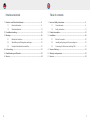
Table of contents
1 User and Safety instructions ...................................................................... 9
1.1 User information ......................................................................... 9
1.2 Safety instructions ...................................................................... 13
2 Product description ..................................................................................... 19
3 Installation .................................................................................................... 20
3.1 Electric Connection .................................................................... 20
3.2 Installing wall opening and ush mounting box .......................... 23
3.3 Connecting the ush mount switching PSU ............................... 27
4 Scope of delivery ......................................................................................... 31
5 Warranty and guarantee .............................................................................. 33
6 Service .......................................................................................................... 35
Inhaltsverzeichnis
1 Benutzer- und Sicherheitshinweise ........................................................... 8
1.1 Benutzerinformation ................................................................... 8
1.2 Sicherheitshinweise .................................................................... 12
2 Produktbeschreibung .................................................................................. 18
3 Montage ........................................................................................................ 20
3.1 Elektrischer Anschluss ............................................................... 20
3.2 Wandönung und Montagedose anbringen ............................... 23
3.3 Unterputz-Schaltnetzteil anschließen ......................................... 27
4 Lieferumfang ................................................................................................ 31
5 Gewährleistung und Garantie ..................................................................... 32
6 Service .......................................................................................................... 34
6 7

8 9
1 Benutzer- und Sicherheitshinweise
Danke, dass Sie sich für ein Qualitätsprodukt von inVENTer entschieden haben!
Dieses Kapitel gibt Ihnen einen Überblick über die grundsätzlichen Sicher-
heitsvorkehrungen für einen sicheren und einwandfreien Betrieb Ihrer Steuereinheit.
1.1 Benutzerinformation
Sicherheits- und Warnhinweiskonzept
Die Sicherheits- und Warnhinweise in dieser Montageanleitung sind einheitlich
aufgebaut und mit einem Symbol auf der linken Seite des Hinweises gekennzeich-
net. Ein Signalwort vor dem Text weist auf die Gefährdungsstufe hin. Beim Auftreten
mehrerer Gefährdungsstufen wird immer der Sicherheitshinweis zur jeweils höch-
sten Stufe verwendet.
Die Sicherheits- und Warnhinweise enthalten die folgenden Informationen:
SIGNALWORT: ART UND HERKUNFT DER GEFAHR. Mögliche
Konsequenzen der Gefahr!
• Maßnahmen zur Vermeidung der Gefahr.
Das Signalwort kennzeichnet die Schwere der Gefahr, die auftritt, wenn sie nicht
vermieden wird:
GEFAHR bedeutet: Schwerer Personenschaden oder Tod droht unmittel-
bar.
WARNUNG bedeutet: Schwerer Personenschaden oder Tod droht mögli-
cherweise.
1 User and Safety Instructions
Thank you for purchasing this high quality product from inVENTer!
This section provides an overview of the basic safty precautions for safe and proper
operation of your controlling unit.
1.1 User Information
Safety and warning instructions
The safety and warning instructions in these installation instructions have a uniform
structure and are marked with a symbol on the left side of the instruction. A signal
word in front of the text also indicates the hazard level. If several hazard levels
occur, the safety note for the highest level is always used.
The safety instructions and warnings contain the following information:
SIGNAL WORD: TYPE AND ORIGIN OF THE HAZARD. Possible
consequences of the danger!
• Measures to avoid hazard.
The signal word indicates the severity of the potential hazard unless the preventive
measures are taken:
DANGER means: Severe danger of serious injury or death.
WARNING means: Possible danger of serious injury or death.

10 11
VORSICHT bedeutet: Leichter/mittlerer Personenschaden droht unmittelbar.
HINWEIS bedeutet: Sachschaden aufgrund eines unerwünschten
Ereignisses/Zustands droht unmittelbar oder möglicherweise.
Wenn Sie diese Zeichen sehen, halten Sie sich an die beschriebenen Maßnahmen,
um mögliche Gefahren und Schäden zu vermeiden.
Weitere Symbole in der Dokumentation
Neben den Sicherheits- und Warnhinweisen werden die nachfolgenden Symbole
verwendet:
Dieses Symbol gibt praktische und nützliche Tipps für den Umgang mit Ihrer
Steuereinheit.
Vor den Handlungssequenzen werden, wenn benötigt, zusätzliche
Werkzeuge und Hilfsmittel für die anfallenden Tätigkeiten aufgezählt.
Die Graphiken zeigen die Innenwand.
► Handlungsanweisung: Fordert den Bediener zu einer Handlung auf.
Handlungsergebnis: Fordert zur Prüfung des Ergebnisses der
Handlungen auf.
Handlungsaugenmerk: Bei dem entsprechenden Montageschritt zu
berücksichtigen.
CAUTION means: Direct danger or minor/signicant injury.
NOTICE means: Direct or possible risk of property damage due to an
adverse event/state.
When presented these signs, follow the measures described to avoid possible
danger or damage.
Additional symbols in the documentation
In addition to the safety and warning signs, the following symbols are used:
This symbol provides practical and useful tips for handling your control unit.
Before the action sequences, additional tools and aids for the activities
involved are listed if needed.
The graphics show the inner wall.
► Action instruction: Prompts the user to perform an action.
Result action: Prompts the user to check results of action.
Action focus: To be taken into account in the corresponding assembly
step.
!
i
!
i

12 13
1.2 Sicherheitshinweise
Die Montageanleitung ist Bestandteil Ihrer Steuereinheit sMove und muss ständig
verfügbar sein (siehe www.inventer.de/downloads). Bei der Übergabe des Systems
an Dritte muss die Information zum Zugang zur Montageanleitung mit übergeben
werden.
Lesen Sie sich vor der Durchführung von Arbeiten am Gerät/System die Montag-
eanleitung sorgfältig durch und beachten Sie alle in diesem Kapitel aufgeführten
Hinweise zur Montage. Beachten Sie darüber hinaus die Sicherheitshinweise, die
den beschriebenen Handlungsanweisungen vorangestellt sind. Die Nichtbeachtung
von Sicherheitshinweisen kann zu Personen- und/oder Sachschäden führen.
Bestimmungsgemäßer Gebrauch
Die Steuereinheit sMove Long (im weiteren Text auch „Regler“ oder „sMove“) ist nur
zur Steuerung der dezentralen iV-Lüftungsgeräte mit Wärmerückgewinnung (Pro-
duktreihen iV-Smart+, iV14-Zero, iV-Light, iV-Compact [jeweils Ventilator Xenion],
Produktreihen iV14-MaxAir, iV-Oce [jeweils Ventilator Xenion EFP] und Produkt-
reihe iV-Twin+ [Ventilator Mini-Xenion]) der inVENTer GmbH zu verwenden.
Dabei sind im Einzelnen zu verwenden:
• Der Regler sMove zur Ansteuerung der im System enthaltenen inVENTer-Lüftungs-
geräte mit Wärmerückgewinnung.
• Die mit dem Regler gekoppelte Sensorik (Hygrostat HYG18, Hygrostat HYG12,
CO2-Sensor CS1 oder Druckwächter) zur Lieferung von Temperatur-, Feuchtigkeits-
und CO2-Werten an den Regler sMove, dem diese wiederum zur Steuerung der
inVENTer-Lüftungsgeräte mit Wärmerückgewinnung dienen.
1.2 Safety instructions
The assembly instructions are part of your sMove control unit and must be available
at all times (see www.inventer.eu/downloads). When handing over the system to
third parties, the information on access to the installation instructions must also be
handed over.
Before carrying out any work on the unit/system, read the assembly instructions
carefully and observe all the assembly instructions listed in this chapter. In addition,
observe the safety instructions that precede the described instructions for action.
Failure to observe safety instructions may result in personal injury and/or damage to
property.
Intented use
The sMove Long control unit (also referred to as “controller” or “sMove” in the fol-
lowing text) is only to be used to control the decentralised iV ventilation devices with
heat recovery (iV-Smart+, iV14-Zero, iV-Light, iV-Compact [Xenion fan in each case],
iV14-MaxAir, iV-Oce [Xenion EFP fan in each case] and product series iV-Twin+
[Mini-Xenion fan]) of inVENTer GmbH.
The following are to be used in detail:
• The sMove controller for controlling the inVENTer ventilation devices with heat
recovery included in the system.
• The sensors coupled with the controller (HYG18 hygrostat, HYG12 hygrostat,
CS1 CO2 sensor or pressure monitor) to supply temperature, humidity and CO2
values to the sMove controller, which in turn uses them to control the inVENTer
ventilation devices with heat recovery.

14 15
• GEFAHR: Die Montage des Gerätes darf nur durch qualiziertes
Elektrofachpersonal erfolgen.
- Beachten Sie beim Verlegen des Netzanschlusskabels die Vorgaben der
Schutzklasse II.
- Führen Sie alle Geräte eines Lüftungssystems auf denselben Sicherungs-
automaten.
- Kabel ausschließlich im spannungsfreien Zustand verlegen und anschließen!
- Die Netzstromversorgung muss den Angaben des Typenschildes entsprechen.
- Trennen Sie vor Arbeiten an elektrischen Anlagen alle betroenen Geräte
von der Stromversorgung.
- Prüfen Sie vor dem Durchführen von Bohrungen, ob sich Leitungen im
Bohrbereich benden.
• WARNUNG: Für den gemeinsamen Betrieb eines Lüftungsgerätes mit Feuer-
stätten müssen Sicherungsmaßnahmen ergrien werden, um das Entstehen
eines Unterdrucks im Gebäude zu verhindern. Die Entscheidung welche
Maßnahmen durchgeführt werden sollen, trit der zuständige Schornsteinfeger
und/oder Bauplaner.
• HINWEIS: Achten Sie auf ausreichende Kontaktierung der Leitungen beim
Anschließen des Reglers sMove.
• HINWEIS: Verlegen von Kabeln, deren Mantel unter Putz nicht putzresistent ist,
führt zu Kurzschluss und Kabelbrand! Verlegen Sie Kabel ohne putzresistenten
Kabelmantel im Leerrohr.
• HINWEIS: Die Verwendung eines zu geringen Leitungsquerschnitts führt
zu einem zu hohen Spannungsabfall und/oder die Kontaktierung ist nicht
gewährleistet!
Verwenden Sie beim Anschluss von Litzen Aderendhülsen mit Kragen.
• HINWEIS: Der Regler verfügt über kratzempndliche Kunststooberächen.
Berühren Sie Komponenten nicht mit öligen und/oder schmutzigen Händen.
Vermeiden Sie den Kontakt mit scharfen oder spitzen Gegenständen.
• DANGER: The unit may only be installed by qualied electricians.
- Observe the specications of protection class II when laying the mains
connection cable.
- Route all devices of ventilation system to the same circuit breaker.
- Only lay and connect cables when they are de-energised!
- The mains power supply must comply with the specications on the type
plate.
- Disconnect all aected devices from the power supply before working on
electrical installations.
- Before drilling, check whether there are any lines in the drilling area.
• WARNING: For joint operation of ventilation devices with replaces, safety
measures must be taken to prevent a negative pressure from developing in
the building. The decision as to which measures should be implemented is
made by the chimney sweep and/or building planner responsible.
• NOTICE: Make sure that the cables have sucient contact when connecting
the sMove controller.
• NOTICE: Laying cables whose sheathing under plaster is not plaster-resistant
will lead to short circuits and cable res! Lay cables without a plaster-resistant
cable sheath in the empty conduit.
• NOTICE: The use of too small cable cross-section leads to a too high
voltage drop and/or contacting is not guaranteed!
• NOTICE: Use wire end ferrules with collars when connecting stranded wires.
• NOTICE: The controller has plastic surfaces that are sensitive to scratches.
Do not touch components with oily and/or dirty hands. Avoid contact with sharp
or pointed objects.

16 17
Nicht bestimmungsgemäßer Gebrauch
Der Regler sMove ist ausschließlich zur Steuerung der im bestimmungsgemäßen
Gebrauch benannten Lüftungsgeräte vorgesehen. Jeder sonstige Gebrauch ist
ausdrücklich untersagt.
Der bestimmungswidrige Gebrauch führt zum Ausschluss jeglicher Haftung-
sansprüche.
Qualiziertes Personal
Das Gerät darf nur in Verbindung mit dieser Dokumentation und der Dokumentation
für die Lüftungsgeräte eingerichtet werden.
Montage, elektrischer Anschluss und Erstinbetriebnahme des Gerätes dürfen nur
von qualiziertem Personal vorgenommen werden. Qualiziertes Personal im Sinne
der sicherheitstechnischen Hinweise dieser Dokumentation sind Personen, die die
Berechtigung haben, Geräte und Stromkreise gemäß den Standards der Sicherheit-
stechnik zu montieren, in Betrieb zu nehmen und zu kennzeichnen.
Konformität
Das Lüftungsgerät entspricht den technischen Sicherheitsanforderungen und
Normen elektrischer Geräte für den Hausgebrauch. Es ist konform mit geltenden
Richtlinien der Europäischen Union und des Vereinigten Königreichs. Der vollstän-
dige Text der EU-Konformitätserklärung ist unter der folgenden Internetadresse
verfügbar: https://www.inventer.de/downloads/ .
Non-intended use
The sMove controller is intended exclusively for controlling the ventilation devices
specied in the intended use. Any other use is expressly prohibited.
Use contrary to the intended purpose leads to the exclusion of any liability claims.
Qualied personnel
The unit may only be set up in conjunction with this documentation and the docu-
mentation for the ventilation devices.
Installation, electrical connection and initial commissioning of the unit may only be
carried out by qualied personnel. Qualied personnel in the sense of the safety
instructions in this documentation are persons who are authorised to install, com-
mission and label devices and circuits in accordance with the standards of safety
engineering.
Conformity
The ventilation device complies with the technical safety requirements and stand-
ards for electrical equipment for domestic use. It conforms to applicable directives of
the European Union and the United Kingdom. The full text of the EU declaration of
conformity is available at the following Internet address:
https://www.inventer.eu/downloads/ .

Ersetzt der Regler sMove s4/s8 Long einen bereits vorhandenen Regler,
beachten Sie zusätzlich die Demontageanleitung Regler. Diese nden Sie
unter www.inventer.de/downloads.
Fahren Sie nach der Demontage mit Schritt 2, Unterputz-Schaltnetzteil
anschließen, fort.
18 19
Der Regler sMove s4/s8 Long gleicht in Aufbau, Bedienung und Funktion
dem sMove s4 bzw. sMove s8.
Weitere Informationen zum Regler sMove entnehmen Sie der beiliegenden
Montageanleitung Regler sMove( Artikelnummer 5021-0027) und
Bedienungsanleitung Regler sMove ( Artikelnummer 5021-0028).
2 Produktbeschreibung
Der Regler sMove ist ein elektronisches Bediengerät zur Ansteuerung der
inVENTer® Lüftungsgeräte mit Wärmerückgewinnung. Er ist in den Varianten s4 oder
s8 in jeweils zwei Ausführungen (Standard oder Flat) erhältlich.
Bei der Version „Long“ handelt es sich um eine zusätzliche Ausführung. Sie eignet
sich insbesondere beim Umbau bereits vorhandener Regler mit Doppelkam-
mer-Dose oder wenn beim sMove s8 mit Unterputz Schaltnetzteil nur eine Dose
verwendet werden soll.
Er zeichnet sich durch sein optisch dezentes, zeitloses und aches Design sowie
eine einfache Montage aus. Die Bedienung des Reglers erfolgt durch Berühren der
kapazitiven Taster und des Schiebereglers auf dem Bedienfeld. Durch integrierte
Leuchtanzeigen dient das Bedienfeld gleichzeitig als optische Rückkopplung/An-
zeige für den Benutzer.
2 Product description
The sMove controller is an electronic operating device for controlling the
inVENTer® ventilation devices with heat recovery. It is available in the variants s4 or
s8, each in two versions (standard or at).
The “Long” version is an additional version. It is particularly suitable when converting
existing controllers with a double-chamber box or if only one box is to be used with
the sMove s8 with ush-mounted switching power supply.
It is characterised by its visually discreet, timeless and at design as well as simple
installation. The controller is operated by touching the capacitive buttons and the
slider on the control panel. With integrated luminous indicators, the control panel
also serves as a visual feedback/indicator for the user.
If the sMove s4/s8 Long controller replaces an existing controller, please also
observe the controller disassembly instructions. These can be found at
www.inventer.eu/downloads.
After disassembly, continue with step 2, Connecting the ush-mounted
switching power supply.
The sMove s4/s8 Long controller is similar in design, operation and function
to the sMove s4 or sMove s8.
For further information on the sMove controller, please refer to the enclosed
installation instructions for the sMove controller ( Item No. 5021-0029)
operation instructions for the sMove controller ( Item No. 5021-0030).
i
i
i
i

20 21
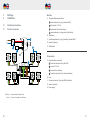
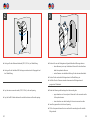
Abbildung 1: Anschlussbeispiel Regler sMove
Figure 1: Connection example controller sMove
Components
A Rear side sMove control unit
1 Connection terminal, 5-pole (fan-BUS)
1 Jumper, 2 X 2-Pin
1 Jumper Service-Settings
1 Connection terminal, 2-pole (external interface)
B Fans
C Connection terminal, 5-pole (fan-BUS distribution)
D Sensors (optional)
E Power supply
Bauteile
A Rückseite Bedienienheit sMove
1 Anschlussklemme, 5-polig (Ventilator BUS)
1 Steckbrücke, 2 X 2-Pin
1 Steckbrücke Service-Einstellugen
1 Anschlussklemme, 2-polig (externe Schnittstelle)
B Ventilatoren
C Verbindungsklemmen, 5-polig (Verteilung Ventilator-BUS)
D Sensorik (optional)
E Schaltnetzteil
3 Montage
3 Installation
3.1 Elektrischer Anschluss
3.1 Electric connection
3
3
3
3
3
3
3
3
3
+ 24 V DC
GND (┴)
DIR1 (III)
VOUT+ (IV)
DIR2 (V)
SC1
SC2
+ 24 V DC
GND (┴)
V IV III
V
IV
III
VIV III
VIV
III
VIV III
VIV
III
VIV
III VIV III
VOUT+
(IV)
DIR1
(III) DIR2
(V)
L
NAC
DC
B
A
D
E
C

22 23
GEFAHR: Oen liegende elektrische Komponenten.
Stromschlag und Verletzung durch spannungsführende Bauteile
(230 V, 50 Hz)!
• Vor Arbeiten an elektrischen Anlagen betroene Geräte von der Strom-
versorgung trennen.
• Vorgaben der Schutzklasse II beim Verlegen des Netzanschlusskabels
beachten.
• Kabel nicht unter Spannung verlegen.
• Netzanschluss- und Signalleitungen getrennt verlegen.
• Systemkomponenten des Lüftungssystems auf den selben Sicherheit-
sautomaten führen.
Montage und Anschluss nur von qualiziertem und geschultem
Personal.
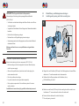
DANGER: Exposed electrical components.
Electric shock and injury from live components (230 V, 50 Hz)!
• Before working on electrical equipment, disconnect aected equip-
ment from power supply.
• Observe the specications of protection class II when laying the
mains connection cable.
• Do not lay cables under voltage.
• Lay mains connection and signal cables separately.
• Route system components of the ventilation system to the same
safety controller.
Installation and connection only by qualied and trained personnel.
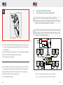
3.2 Wandönung und Montagedose anbringen
3.2 Installing wall opening and ush mounting box
►Bringen Sie zwei Fräslöcher (Ø 68 mm) für die Montagedose mit einem Mitten-
abstand von 71 mm übereinander an der Innenwand an.
►Entfernen Sie die Stege zwischen den Fräslöchern (Linie).
Die Wandönung ist erstellt.
►Make two routed holes (Ø 68 mm) for the mounting box with a centre-to-cen-
tre distance of 71 mm one above the other on the inside wall.
►Remove the bars between the routed holes (line).
The wall opening is created.
Ø 68
71
Ø 68
71
1

24 25
► Verlegen Sie das Netzanschlusskabel (230 V, 50 Hz) zur Wandönung.
►Verlegen Sie die Ventilator-BUS-Leitungen zwischen dem Lüftungsgerät und
der Wandönung.
►Lay the mains connection cable (230 V, 50 Hz) to the wall opening.
►Lay the fan BUS cables between the ventilation device and the wall opening.
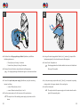
►Brechen Sie aus der Montagedose folgende Kabeldurchführungen heraus:
• obere Kammer: je eine pro Ventilatoren-Paar und für das Anschluss-
kabel des optionalen Sensors.
• untere Kammer: eine kabeldurchführung für das netzanschlusskabel.
► Setzen Sie die vorbereitete Montagedose in die Wandönung ein.
►Verfüllen Sie den Freiraum zwischen Innenwand und Montagedose mit
geeignetem Füllmaterial.
►Break the following cable bushings from the mounting box:
• upper chamber: one for each pair of fans and for the connection cable
of the optional sensor
• lower chamber: one cable bushing for the mains connection cable.
►Insert the prepared box into the wall opening.
►Fill the free space between the inner wall and the mounting box with suitable
lling material.
3 2

26 27
►Lay the fan BUS cables (each in pairs, insulation stripped 8 mm) and the con-
nection cable for optional sensor in the upper chamber of the mounting box.
►Lay the mains connection cable in the lower chamber of the mounting box.
►Insulate the protective contact wire with a clamp.
The mounting box is installed.
►Verlegen Sie die Ventilator-BUS-Leitungen (jeweils paarweise, Abisolierung 8
mm) und das Anschlusskabel für den optionalen Sensor in die obere Kammer
der Montagedose.
►Verlegen Sie das Netzanschlusskabel in die untere Kammer der Montagedose.
►Isolieren Sie die Ader Schutzkontakt mit einer Klemme.
Die Montagedose ist angebracht.
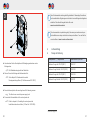
3.3 Unterputz-Schaltnetzteil anschließen
3.3 Connecting the ush mounted switching PSU
3
3
3
3
3
3
3
3
3
V IV III
V
IV
III
VIV III
VIV
III
VIV III
VIV
III
VIV
III VIV III
+ 24 V DC
GND (┴)
VOUT+
(IV)
DIR1
(III) DIR2
(V)
+ 24 V DC
GND (┴)
DIR1 (III)
VOUT+ (IV)
DIR2 (V)
SC1
SC2
L
NAC
DC
Abbildung 2: Anschlussbeispiel Regler sMove Unterputz - Schaltnetzteil
Figure 2: Connection example controller sMove ush mounted PSU
Wird der sMove in Verbindung mit einem Unterputz-Schaltnetzteil
angeschlossen, empfehlen wir die Verteilung der Kabel zwischen Regler und
Ventilator in einer separaten Montagedose zu realisieren.
If the sMove is connected in conjunction with a ush-mounted switched-mode
power supply, we recommend distributing the cables between the controller
and the fan in a separate mounting box.
i
i
4

28 29
►Schließen Sie die Eingangsleitungen Netzteil (blau/braun) mithilfe der
Verbindungsklemme an
• Phase (braun) mit Leitung L verbinden.
• Neutral-Leiter (blau) mit Leitung N verbinden.
►Platzieren Sie das Netzteil im unteren Bereich der Montagedose.
Die Ausgangsleitungen Schaltnetzteil ragen in den Innenraum hinein.
►Connect the input leads power supply (blue/brown) using the connecting
terminal as follows:
• connect Phase (brown) to line L.
• connect Neutral conductor (blue) to line N.
►Place the power supply unit in the lower area of the mounting box.
The output lines of the switching power supply unit protrude into the
interior.
►Verlegen Sie das Ausgangskabel Netzteil (rot [+], schwarz [-], entspricht Be-
triebsspannungkabel) in die obere Kammer der Montagedose.
►Setzen Sie die Trennplatte ein.
Das Ausgangskabel des Netzteils bendet sich unter der Kabeldurch-
führung der Trennplatte.
►Lay the power supply output cable (red [+], black [-], corresponds to operating
voltage cable) in the upper chamber of the mounting box.
►Insert the divider plate.
The output cable of the power supply unit is located under the cable
gland of the separating plate.
1 2
!
!
!
!

30 31
3
►Verschrauben Sie die Grundplatte mit 4 Befestigungsschrauben an der
Montagedose.
Die Blindabdeckung deckt das Netzteil ab.
►Fahren Sie mit der Montage der Bedieneinheit fort.
Siehe Kapitel 5,4: Bedieneinheit montiert
Montageanleitung sMove ( Artikelnummer 5021-0027).
►Screw the base plate to the mounting box with 4 fastening screws.
The blind cover covers the power supply unit.
►Proceed with the installation of the control panel unit.
Refer to chapter 5,4: Installing the control panel unit
Installation instructions sMove ( Item No. 5021-0029).
4 Lieferumfang
4 Scope of delivery
Komponente | Components Artikelnummer | Item No.
sMove s4 Long inkl. UP-NT (PSU1)) 1003-0107
sMove s4 Long-Flat inkl. UP-NT (PSU1)) 1003-0108
sMove s8 Long inkl. UP-NT (PSU1)) 1003-0109
sMove s8 Long-Flat inkl. UP-NT (PSU1)) 1003-0110
1) PSU=Power Supply Unit
Diese Dokumentation wird regelmäßig aktualisiert. Notwendige Korrekturen
und zweckdienliche Ergänzungen sind stets in den nachfolgenden Ausgaben
enthalten. Die aktuelle Ausgabe nden Sie unter
www.inventer.de/downloads.
This documentation is updated regularly. Necessary corrections and expe-
dient additions are always included in subsequent editions. You can nd the
current edition at www.inventer.eu/downloads.
!
!
!
!
i
i

32 33
5 Gewährleistung und Garantie
Gewährleistung:
Die Gewährleistung bezieht sich auf die Mängelfreiheit beim Erwerb und deckt alle
Mängel ab, die zum Zeitpunkt des Erwerbs vorhanden waren. Beachten Sie den
bestimmungsgemäßen Gebrauch, um den Gewährleistungsanspruch aufrechtzuer-
halten.
Außerhalb Deutschlands gelten die nationalen Gewährleistungsbestimmungen des
Landes, in dem das System vertrieben wird. Wenden Sie sich an den Händler ihres
Heimatlandes.
Garantie:
Die inVENTer GmbH gibt 5 Jahre Garantie auf alle Elektronikbauteile. Diese deckt
einen vorzeitigen Produktverschleiß ab.
Gewährleistungs- und Garantieanspruch:
Informationen zu den Garantiebestimmungen nden Sie unter
www.inventer.de/garantie.
Im Fall eines Gewährleistungs- oder Garantieanspruches kontaktieren Sie den für
Sie zuständigen Händler oder Werksvertreter.
Senden Sie das vollständige Gerät in jedem Fall zurück an den Hersteller.
Der Garantieanspruch ist ein zusätzliches Angebot des Herstellers und berührt in
keiner Weise geltendes Recht.
5 Warranty and guarantee
Warranty:
The warranty refers to freedom from defects at the time of purchase and covers all
defects that were present at the time of purchase. Observe the intended use in order
to maintain the warranty claim.
Outside Germany, the national warranty regulations of the country in which the
system is sold apply. Contact the dealer in your home country.
Guarantee:
inVENTer GmbH provides a 5-year warranty on all electronic components. This
covers premature product wear.
Warranty and guarantee claim:
Information on the warranty conditions can be found at.
www.inventer.eu/guarantee.
In the event of a warranty or guarantee claim, contact the dealer or factory repre-
sentative responsible for you.
In any case, send the complete unit back to the manufacturer.
The warranty claim is an additional oer by the manufacturer and does not aect
applicable law in any way.

34 35
6 Service
Reklamation:
Überprüfen Sie die Lieferung bei Erhalt, anhand des Lieferscheines, auf Vollständig-
keit und Transportschäden. Reklamieren Sie fehlende Positionen unverzüglich, spä-
testens innerhalb von 14 Tagen, bei Ihrem Lieferanten, Händler oder Werksvertreter.
Zubehör- und Ersatzteile:
Wenden Sie sich zur Bestellung von Komponenten für Ihr Lüftungsgerät an Ihren
Händler oder Werksvertreter.
Technischer Kunden-Service:
Kontaktieren Sie zur technischen Beratung unsere Service-Mitarbeiter:
+49 (0) 36427 211-333
service@inventer.de
Zusätzlich können Produktreklamationen/technische Defekte bei unserem
technischen Kunden-Service oder direkt über das Formular auf unserer Homepage
angemeldet werden: www.inventer.de/reklamation.
6 Service
Complaints:
Check the delivery for completeness and transport damage on receipt, using the
delivery note. Complain about missing items immediately, at the least within 14 days,
to your supplier, dealer or factory representative.
Accessories and spare parts:
Contact your dealer or factory representative to order components for your
ventilation device.
Technical customer service:
Contact our service sta for technical advice:
+49 (0) 36427 211-333
service@inventer.de

Änderungen vorbehalten.
Keine Haftung für Druckfehler.
inVENTer GmbH
Ortsstraße 4a
D-07751 Löberschütz
www.inventer.de
www.inventer.eu
Subject to change without notice.
No liability for printing errors.
Artikelnummer | Item No.: 5021-0009
Version: 2.0 – 11/2022
-
 1
1
-
 2
2
-
 3
3
-
 4
4
-
 5
5
-
 6
6
-
 7
7
-
 8
8
-
 9
9
-
 10
10
-
 11
11
-
 12
12
-
 13
13
-
 14
14
-
 15
15
-
 16
16
-
 17
17
-
 18
18
-
 19
19


inVENTer sMove s4 Long Installationsanleitung
- Typ
- Installationsanleitung
in anderen Sprachen
Verwandte Artikel
-
inVENTer Pure p4 Controller Pure Benutzerhandbuch
-
-
-
-
-
-
inVENTer PURE Bedienungsanleitung
-
-
-
Andere Dokumente
-
Maico WRG 35 Mounting And Operating Instructions
-
ABB i-bus EIB Series Operating Instructions Manual
-
-
Warmup WA-XSTAT-V Bedienungsanleitung
-
Panlux RO-C53/S Bedienungsanleitung
-
-
CAME DIR / R-Series Bedienungsanleitung
-