
Vor der Demontage ist sicherzustellen, dass die Versorgungsspannung für das Gerät abgeschaltet ist.
Austausch der Antennenbaugruppe am Micropilot M FMR250
(mit erhöhter Nahbereichsdynamik - 26 GHz)
im Beispiel:
Gehäuse F12
Das Gerät darf nur von Fachpersonal repariert und gewartet werden. Dabei sind die Gerätedokumentation, die einschlägigen
Normen, die gesetzlichen Vorschriften und die Zertifikate zu beachten!
Es dürfen nur modulare Baugruppen gegen identische original Endress+Hauser Ersatzteile ausgetauscht werden!
0
1
2
EA0014F/00/a2/10.09
71091596
Ausgabe/revision: 1
1
2
3
4
1
2
5
Terminal
ENDRESS+HAUSERENDRESS+HAUSER
E
N
D
R
E
SS+
H
A
U
SE
R
Order Code:
Ser.-No.:
Made in Germany Maulburg
T >70°C :
A
t
>
85
°C
IP
65
Messbereich
Measuring range
U 16...36 V DC
4...20 mA
max. 20 m
8
7
10
6
Made in Germany MaulburgMade in Germany Maulburg
E
N
D
RE
SS+
H
A
U
SE
R
Order Code:
Ser.-No.:
Made in Germany Maulburg
T >70°C :
A
t
>
8
5
°C
IP
6
5
Messbereich
Measuring range
U 16...36 V DC
4...20 mA
max. 20 m
10
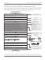
Ansicht auf die Unterseite
des Elektronikmoduls:
3
4
Benötigtes Werkzeug:
1
2
3
4
5
6
7
8
9
10
11
12
12
• Kreuzschlitzschraubendreher Größe 1
• Schlitzschraubendreher für M3 / M4
• Absteckwerkzeug für Antennenstecker
(Best. Nr. 5200 7646)
• Inbusschlüssel SW2,5; SW4
• Steckschlüssel oder Gabelschlüssel SW7
Drehmomentschlüssel (3 Nm)
• Ggf. eine Pinzette
Deckel abschrauben (4 Umdrehungen).
Wenn vorhanden, das Display durch Hochdrücken
des Hakens aus der Halterung lösen.
Displaykabel abstecken.
Schrauben der Abdeckhaube lösen und Haube abnehmen.
Am Klemmenmodul die Kabel lösen
(nur bei Gehäuse F12 und F23).
Unteren Widerhaken am Modulgehäuse leicht
eindrücken und ...
... Frontplatte nach vorn abziehen.
Verbindungskabel zum Klemmenmodul von der
Elektronik abstecken (nur bei Gehäuse F12/F23).
Klemmenmodul aus dem Gehäuse ziehen
(nur bei Gehäuse F12/F23).
Die 2 Befestigungsschrauben des Elektronikmoduls lösen.
Elektronikmodul aus dem Gehäuse ziehen.
Das Antennenkabel mittels Werkzeug abstecken.
Die Elektronik ist nun ausgebaut, jetzt kann die Antennen-
baugruppe ausgetauscht werden (Beschreibung umseitig).
Nach dem Austausch der Antennbaugruppe erfolgt der Einbau
der Elektronik umgekehrter Reihenfolge.
Achtung!
• Antennenkabel ( ) über eine Schlaufe an das HF-Modul
anstecken und in der Mulde fixieren.
Vor dem Ausbau der Antennenbaugruppe muss aus dem
jeweiligen Gehäuse F12, F23 oder T12 die Elektronik
ausgebaut werden:
• Auf klemmfreien Sitz der Kabel achten
10
11
12
71091596
1
2
3
4
9
Ex i-Geräte:
Ex d-Geräte:
Die Reparatur ist so durchzuführen, dass die Spannungsfestigkeit der Ex ia Stromkreise gegen Erde erhalten bleibt.
Bei Bedarf kann eine Prüfung mit 500 Veff über 60 s durchgeführt werden.
Es ist zu prüfen, dass die Gewinde im Gehäuse und am Gehäusedeckel nicht beschädigt sind.
Im anderen Fall muss das entsprechende Teil ausgetauscht werden.
0
1
2

Austausch der Antennenbaugruppe am Micropilot M FMR250
Bei zertifizierten Geräten ist die Reparatur eines Gerätes zu dokumentieren!
Hierzu gehört die Angabe der Geräte-Seriennummer, Reparaturdatum, Art der Reparatur und ausführender Techniker.
0
1
2
Endress+Hauser Maulburg
Austausch der Antennenbaugruppe am Micropilot M FMR250
EA0014F/00/a2/10.09
3
1
2
E
N
D
R
E
S
S
+
H
A
US
E
R
M
IC
R
O
P
IL
O
T II
IP
6
5
Order C
o
de:
S
er.-N
o
.:
M
essb
ere
ich
Measuring range
U
16...36
V
D
C
4...20 m
A
ma
x.
20 m
Made in Germany Maulburg
T >70°C
:
A
t >
85
°C
Nach dem Austausch einer Antennenbaugruppe ist in jedem
Fall eine neue Kalibration des Micropilot M FMR250
erforderlich. Die notwendigen Vorgänge sind im Anhang
"Grundkalibration" beschrieben.
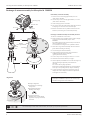
Anschlagschraube
Antennenkabel
Feststell-
schraube
Erdungsfeder
Ausrichtung
2
Ausbau der Antennenbaugruppe
1
2
3
4
5
Montage der Antennenbaugruppe und Zusammenbau des
Gerätes:
Feststellschraube am Gehäuse etwa eine Umdrehung lösen
(Innensechskantschlüssel SW4).
Anschlagschraube im Gehäuse ca.4-5Umdrehungen
ausschrauben (Innensechskantschlüssel SW2,5).
Gehäuse vom Prozessanschluss abdrehen.
Der Prozessanschluss mit Antennenkabel und Mikrowellen-
einkopplung ist eine komplette Baugruppe und kann nicht
zerlegt werden.
Das Antennenhorn bzw. den Parabolreflektor demontieren,
dazu die 4 Sechskantschrauben (SW7) lösen.
• Antennenhorn / Parabolreflektor mit 4 Sechskantschrauben
M4 (SW7) an die neue Antennbaugruppe schrauben, 3 Nm.
Bei Parabolantennen ist die Antennenbaugruppe immer
auf die Größe des jeweiligen Reflektors abgestimmt.
Es darf kein Reflektor mit abweichender Größe angebaut
werden!
• O-Ring an der Gehäuseaufnahme vor dem Aufsetzen des
Gehäuses mit etwas Silikonfett einschmieren.
• Gehäuse auf die Antennenbaugruppe schrauben.
• Anschlagschraube bis zum Anschlag einschrauben,
dann ½ bis 1 Umdrehung wieder lösen.
• Elektronik wieder ins Gehäuse einbauen, siehe Seite 1.
Achtung:
• Die Erdungsfeder im Gehäuse so ausrichten, dass diese mit
dem Prozessanschluss eine leitende Verbindung herstellt
(Erdpotenzial zur Antenne).
• Komplett montiertes Gerät wieder auf dem Behälter
montieren und so ausrichten, dass Ausrichtmarkierung zur
Behälterwand zeigt.
Bei Ausführungen mit Ausrichtvorrichtung:
Bitte beachten Sie zusätzlich die Hinweise zur Montage und
Einstellung in der Betriebsanleitung, Kapitel “Montage”.
•
Feststellschraube fest anziehen.
Gehäuse auf dem Prozessanschluss so drehen, dass der
Anschlussraum bzw. die Bedienungselemente leicht
zugänglich sind. Dann die
4
5
Ausricht-
markierung
90°
90°
Ausrichtmarkierung:
• Gewinde /UNI Flansche:
Siehe Abb. oben
• ANSI, DIN oder JIS Flansche:
Markierung auf dem Flansch
• Ausrichtvorrichtung:
Markierung am Gehäuseadapter

E
1
2
3
5
7
8
9
10
11
12
13
14
15
1
2
3
4
E
N
D
R
E
S
S
+
H
A
U
S
E
R
M
I
C
R
O
P
I
L
O
T
I
I
ENDRESS+HAUSER
MICROPILOT II
I
P
6
5
IP 65
Order
Code:
Ser.-N
o.:
Order Code:
Ser.-No.:
Messbereich
M
easuring r
a
nge
Messbereich
M
e
asuring range
U 16...36V D
C
4...20 m
A
U 16...36V DC
4.
..20 mA
m
ax.20 m
max.20 m
Made in Germany MaulburgMade in Germany Maulburg
T >70°C :
A
t
>8
5
°C
T >70°C :
A
t
>
85°C
E
N
D
R
E
S
S
+
H
A
U
S
E
R
ENDRESS+HAUSER
Z = Z + (field 0D04 - E)
new old
Z is in field 0D72
old
6
• ohne Werks-Ausblendung: Error W511
• der Ausblendbereich muss frei von
Objekten sein.
Anschließend steht Feld 053
wieder auf "aus"
Zur Verriegelung der Bedienmatrix unter Gruppenauswahl --> Diagnose --> Feld
"Freigabecode" (Matrixfeld 0A4) 100 eingeben.
Servicematrix und Kundenparameter freigeben: In der Bedienmatrix unter Gruppenauswahl die
Ebene "Diagnose" anwählen und dort im Feld "Freigabecode" 300 eingeben (Matrixposition 0A4).
In der Bedienmatrix unter Gruppenauswahl --> System-Parameter --> Feld "Längeneinheit"
die gewünschte Längeneinheit auf Meter oder Feet einstellen (Matrixposition 0C5).
In der Servicematrix unter Gruppenauswahl --> Service --> Antenna table --> Feld "antenna type"
(Matrixposition 0D81) die entsprechende Antenne auswählen
In Bedienmatrix unter Gruppenauswahl --> erweiterter Abgleich --> Submenu Abgleichauswahl
• Ausblendung --> Feld "Ausblendbereich" (Matrixposition 052) den auszublendenden Bereich
eingeben (max. Bereich ist ).10 m
In der Servicematrix unter Gruppenauswahl --> Service --> Mapping --> Feld "factory map valid"
2=reset auswählen (Matrixpos. 0D34). Eine noch vorhandene Werksausblendung wird gelöscht.
Antenne, HF-Modul, Elektronik und
Display sind zusammengesteckt
In der Servicematrix unter Gruppenauswahl --> Service --> Info --> Feld "unfiltered distance"
(Matrixposition 0D04) Messwert auslesen und verrechnen. Neu ermittelte Z-Distanz in Service-
ebene --> Module in Feld "zero distance" eingeben (Matrixposition 0D72).
Elektr. Z-Distanz (gilt ab Mikrowellenmodul bis zur Antenne)
• Typische Werte der Z-Distanz in Abhängigkeit der jeweiligen Antenne:
Ermittlung der genauen Z-Distanz:
In definiertem Abstand (z.B. 5,00 m) einen Reflektor (Blechtafel o.ä.) positionieren ...
•
Ende der Grundkalibration
Metalltafel
E = 5,00 m
(freies Feld)
Aufnahme der Werks-Ausblendung (factory map) vorbereiten: In der Servicematrix unter Gruppen-
auswahl --> Service --> Mapping --> Feld "factory map valid" auf "on" schalten (Matrixpos. 0D34).
In der Bedienmatrix unter Gruppenauswahl --> erweiterter Abgleich --> Feld "starte Ausblendung"
(Matrixposition 053) die Ausblendung "an"-schalten (Ausblendung dauert ein paar Sekunden).
In der Bedienmatrix unter Gruppenauswahl --> erweiterter Abgleich --> Feld "Distanz prüfen"
und "4 = manuell" auswählen (Matrixposition 051).
Einschraubstück
mit konischem
Gewinde
Flansch
Definition des Messanfangs E
Gerät wieder in den Prozess einbauen. Aufnahme der Störechoausblendung: In der Bedienmatrix
unter Gruppenauswahl --> erweiterter Abgleich --> Feld "starte Ausblendung" (Matrixposition 053)
die Ausblendung "an"-schalten (Ausblendung dauert ein paar Sekunden).
Nach dem Löschen springt Feld
wieder auf "off"
E= im Beispiel 5 m
Parabolantenne
Hornantenne
Auswahl:
In der Servicematrix unter Gruppenauswahl --> Service --> Antenna table --> Feld "total length"
(Matrixposition 0D83) [mm/inch]die Gesamtlänge der Antenne eingeben
In Bedienmatrix unter Gruppenauswahl --> erweiterter Abgleich --> Submenu Abgleichauswahl
• allgemein --> Feld "Blockdistanz" (Matrixposition 059).eingeben [mm/inch]
Blockdistanz
FMR250 = 400 mm + Antennenlänge
In der Servicematrix unter Gruppenauswahl --> Service --> Antenna table --> Feld " length"
(Matrixposition 0D8 ) [mm/inch]
inactive
2 die inaktive Länge der Antenne eingeben
ohne Verlängerung = 0 mm
250 mm Verlängerung = 250 mm
450 mm Verlängerung = 450 mm
Antennenlänge
• ohne Verlängerung:
Hornantenne DN80/100: 261 / 480 mm
Parabolantenne DN200/250: 111 / 126 mm
• mit 250 mm Verlängerung:
Hornantenne DN80/100: 511 / 730 mm
ParabolantenneDN200/250: 361 / 376 mm
• mit 450 mm Verlängerung:
Hornantenne DN80/100: 711 / 930 mm
Parabolantenne DN200/250: 561 / 576 mm
Grundkalibration des Micropilot M FMR250 nach Austausch der Antennenbaugruppe
Die Antenne, das Mikrowellenmodul sowie die signalverarbeitende Elektronik mit dem Parameterspeicher sind systembestimmend und
verändern bei einem Austausch die Messeigenschaften des Gerätes. Deshalb ist es wichtig eine Grundkalibration nach einem
Baugruppenwechsel mit dem Gerät durchzuführen. Hierfür ist es notwendig, das Gerät komplett mit Antenne aus dem Behälter
auszubauen. Dann ist es sinnvoll das Gerät in einer Spannvorrichtung oder einem Prüfblock zu fixieren und von einer externen Strom-
versorgung zu speisen.
Nach diesem Vorgang sind außerdem alle weiteren Abgleiche durchzuführen, Voll- Leer abgleich, Sicherheitseinstellungen, Linearisierung
usw. (siehe Betriebsanleitung).
Für PROFIBUS PA und Fieldbus FF
“Freigabecode” 33 300 eingeben
Für PROFIBUS PA und Fieldbus FF
“Freigabecode” 2457 eingeben
Endress+Hauser Maulburg
3
Austausch der Antennenbaugruppe am Micropilot M FMR250
EA0014F/00/a2/10.09
4
ohne/250 mm/450 mm
Antennenverlängerung Z-Distanz (mm)
Hornantenne 800 / 1030 / 1180
Parabolantenne 700 / 900 / 1100

00
01
04
05
0 1 2 3 4 5 6 7
8 9
00.000
06
008
Grund-
abgleich
Ausgang bei
Echoverlust
• Alarm
• Halten
• Rampe %/min
*
Medium Eigensch.
• DK unbekannt
• DK < 1.9
• DK 1.9 ... 4
• DK 4 ... 10
• DK > 10
Messbedingungen
• Standard
• Oberfläche ruhig
• Oberfl. unruhig
• zusät. Rührwerk
• schnelle Änderg.
• Test: Filter aus
Verzögerung
Zeit bei Echo-
verlust
max. 4000 [s]
( 0 s)
*
Rohr-
durchmesser
Innendurchmeser
Bypass/Schwallrohr
Abgleichauswahl
(nicht bei ToF Tool)
Sicherheits-
einstellungen
Lineari-
sierung
Füllstand/
Restvolumen
Rampe
%MB/min
Sicherheits-
abstand
ab Antennenspitze
oder Hornkante
im Sicherheits-
abstand
• Alarm
• Warnung
• Selbsthaltung
*
Überfüll-
sicherung
• standard
• WHG
Reset
Selbsthaltung
• nein
• ja
erweiterter
Abgleich
Endwert Mess-
bereich [%]
Linearisierung
Tabellen Nr.
Linearisierung
Füllstand [m]
Linearisierung
Volumen [%]
nächster Punkt:
• ja
Kundeneinheit
s. Tabelle
aktuelle
Ausblenddistanz
Ausblendung
• inaktiv
• aktiv
• löschen
starte Ausblendg.
aus
an
Echoqualität
[dB]
Integrationszeit
[s]
Füllhöhenkorrektur
[m]
wird zum gemess.
Füllstand addiert
Blockdistanz
[m]
•
Distanz prüfen
Distanz = ok
• zu klein
• manuell
Bereich Ausblend
Eingabe des ausbl.
Bereiches
Gruppen-
auswahl
Micropilot M FMR24x / 250, Menüstruktur HART (Anzeigemodul)
Ausgang bei
Alarm xx.xx mA
Ausgang bei
Alarm
• MIN (3.6 mA)
• MAX (22 mA)
• Halten
*
Endwert Mess-
bereich [%]
Zylinder-
durchmesser [m]
Tankgeometrie
• Klöpper-Deckel
• zylindr. liegend
• Flachdeckel
• Kugeltank
• Bypass
• Schwallrohr
Messwert
Kundeneinheit
s. Tabelle
Kundeneinheit
s. Tabelle
Softwareversion
01.05.xx
Ausgabe Okt.06
Rücksprung zur
Gruppenauswahl
Rücksprung zur
Gruppenauswahl
Rücksprung zur
Gruppenauswahl
Sprung zum
Matrixfeld 008
Sprung zum/von
Matrixfeld 0C9
• Füllstand
(m, ft, in)
• Restvolumen
(m, ft, in)
• erweiterte
Ausblendung
• Ausblendung
• zu gross
• unbekannt
• Anwenderspezif.
• nein
Linearisierung
• Linear [%]
• manuell
Medium Eigensch.
• unbekannt
• DK 1.6 ... 1.9
• DK 1.9 ... 2.5
• DK 2.5 ... 4.0
• DK 4.0 ... 7.0
• DK > 7.0
Messbedingungen
• Standard
• langsame Änder.
• schnelle Änder.
• Test: Filter aus
Abgleich leer
[ m ]
Abstand Flansch
zu min. Füllstand
Distanz/Mess-
wert
• Distanz m
• Messwert %
Sprung zum
Matrixfeld 51
Tankgeometrie
• unbekannt
• Metallsilo
• Betonsilo
• Bunker
• Dome
• offene Halde
• Bandbelegung
Rücksprung zur
Gruppenauswahl
Medium Typ
• eitFlüssigk
• Schüttgut
• Füllstand TE
(Kundeneinheit)
• Restvolumen TE
(Kundeneinheit)
Abgleich voll
[ m ]
Messspanne
Abgleich leer
[ m ]
Abstand Flansch
zu min. Füllstand
Abgleich voll
[ m ]
Messspanne
4 mA Wert
[%]
20 mA Wert
[%]
12: ton
13: m
14: ft
15: mm
16: inch
17: none
Kommunikations-
adresse [0...15]
(wenn > 0 dann
Multidropfunktion,
Stromausgang auf
4 mA fixiert!)
Ausgang
Präambelanzahl
für HART [4...20]
Grenze Messwert
• aus
• an
Stromausg. Modus
fester Strom
4 mA
Ausgangsstrom
x.xx mA
Simulation
• aus
• Sim. Füllstand
• Sim. Volumen
• Sim. Strom
Simulationswert
Rücksprung zur
Gruppenauswahl
6: ft3
7: us gal
8: i gal
9: kg
10: t
11: lb
• Standard
• fester Strom
• Stromlupe
• lösche Tabelle
• zylindr. liegend
• halbautomatisch
Fortsetzung
der Menüstruktur
siehe nächste Seite
Auswahl der Kundeneinheiten
0: %
1: litre
2: hl
3: m3
4: dm3
5: cm3
• allgemein
• Tabelle ein
( 0 s)
*
*
= Einstellungswerte nur für WHG
Messwert
4

0 1 2 3 4 5 6 7
8 9
xx dB
Micropilot M FMR250, Menüstruktur HART (Anzeigemodul)
Softwareversion
01.05.xx
lösche letz. Fehler
•
beibehalten
• löschen
Rücksetzen
333: Kundenpara-
meter HART
33 333: Kundenpara-
meter PA/FF
Hüllkurve
Anzeige
Diagnose
Sprache
zur Startseite
3...9999 Sekunden
Anwendungspara-
meter
•
(V0H2-3-4)
nicht geändert
• geändert
Anzeigeformat
• dezimal
• ft-in-1/16"
Anzeigetest
(nur Display)
• aus
• an [1s]
Fernsteuerung
• aus
• an
• rücksetzen
Trennungszeichen
• . (Punkt)
• , (Komma)
Darstellungsart
• Hüllkurve
• Hüllkurve + FAC
• Hüllkurve + Ausbl.
Kurve lesen
• einzelne Kurve
• zyklisch
Nach-
komma-
stellen
Messstelle
tag No.
Seriennummer
Protokoll +
Software Nr.
Anzeigeformat:
Vxx.yy.zz.prot
Längeneinheit
• m
• ft
• mm
• inch
Download Mode
• nur Parameter
• Param.+Ausblen.
• Ausblendung
System
Parameter
xx: HW-Version
yy: SW-Version
zz: SW-Revision
prot: Protokollname
• English
• Deutsch
• Francais
• Espanol
• Italiano
• Nederlands
• Japanisch
gemessene
Distanz [m]
gemessener
Füllstand [m]
zur Servicematrix
Beispiel:
V01.05.00HART
Fortsetzung der
Menüstruktur HART
aktueller Fehler
letzter Fehler
• X
• X.X
• X.XX
• X.XXX
Antennen-
verlängerung
(nicht FMR250)
von 057
nach 058
0E
09
0A
0C
Ausgabe 10.06
Rücksprung zur
Gruppenauswahl
Rücksprung zur
Gruppenauswahl
Rücksprung zur
Gruppenauswahl
Rücksprung zur
Gruppenauswahl
5
Freigabecode
HART / PA+FF
100 / 2457: Kundenmatrix editierbar
200 / 33200: Kunden-/Servicematrix lesbar
300 / 33300: Kunden-/Servicematrix editierbar
33 998: WHG verriegelt (FMR250 keine Zulassung WHG)
33 999: Hardware Verriegelung (nur bei FF)

Info
Distance
MAM filter length
(5)*
MAM filter border
(1)*
hysterese width
(0)*
min. low pass
max. fill. speed
(0)*
max. drain speed
(0)*
unfiltered
distance raw
Envelope
mapping adder
envelope
smoothing
mapping
scan rate
edge detect. mode
0: front 1: behind
2: middle of echo
first echo factor
customer spec.*
tank bottom det.
• off* • on
zero distance
antenna type
• horn aerial
• dish antenna
• rod aerial
• planar antenna
D/A adjust 4 mA
not PROFIBUS/FF
D/A adjust
20 mA
not PROFIBUS/FF
device
ID number
display version
calc. cycle time
software version
application
parameter vers.
application
inactive length
total length
max. measuring
distance
Wire type
• 2 wire • 4 wire
amplitude
reference pulse
position
reference pulse
max. sample
distance
min. amplitude
tank bot. detec.
max. level
tank bot. detec.
FEF threshold
FEF edge
present FEF
fill / drain
speed
mapping
average
FAC adder
(6)*
FAC scan rate
range factory
map
fact. map. valid
0=off;1=on;2=reset
edge parameter
cust. map valid
0:not active, 1:active
fact. map valid
0:not active, 1:active
max. ampl.
over FAC
envelope
energy
present edge
parameter
Mapping
Edge
First echo
Tank bottom
detection
Module
Antenna
table
present
amplitude
amplitude over
mapping
amplitude
over FAC
unfiltered
distance
present
edge parameter
present
first echo factor
device name
order code
0D0
0D1
0D2
0D3
0D4
0D5
0D6
0D7
0D8
0D9
0DC
0DD
back to
function group
back to
function group
back to
function group
back to
function group
back to
function group
back to
function group
back to
function group
back to
function group
back to
function group
back to
function group
back to
function groupl
0 1 2 3 4 5 6 7
8 9
Micropilot M FMR24x / 250, service matrix HART (display module)
System 1
System 2
0D00
0D10
0D20
0D30
0D40
0D50
0D60
0D70
0D80
0DC0
0DD0
0D01
0D02
0D03
0D11
0D12
Service
Softwareversion
01.05.xx
HF module
0: µP III.3
1:
(+35 dB)
µP III.5
(+20 dB)
Savitzky Golay
merging
echoes
merging
window
merging echo
distance
envelope
statistics.up
envelope
statistics down
max. low pass
delta at min.
merging
ratio
FEF at near
dist.
FEF dist. near
FEF dist. far
range TBD
empty limiter
Algorithm 1
0D80
delay timer
echo found
delay
echo lost
delay
min. jump
delay
jump delay
echo window
FAC mode
back to
function group
0D
Oct. 2006
6

0
1
2
Exchange of antenna assembly for Micropilot M FMR250
(with increased near distance dynamic, 26 GHz)
The instrument may only be repaired and maintained by qualified personnel. The instrument documentation, applicable standards,
legal requirements and certificates must be observed!
Modular assemblies may only be exchanged against identical original Endress+Hauser spare parts!
It must be ensured that the supply voltage has been disconnected from the instrument before disassembly.
EA0014F/00/a2/10.09
71091596
Ausgabe/revision: 1
As example:
housing F12
View to the bottom side
of electronic module
Required tools:
1
2
3
4
5
6
7
8
9
10
11
12
12
• Philips screw driver size 1
• Flat screw driver for M3 / M4
• Unplug tool for antenna plug
(order-No. 5200 7646)
• Allen key AF2.5 mm, AF4 mm
• Socket key or wrench AF7 mm
torque wrench (3 Nm)
• If necessary tweezers
Unscrew lid (4 turns).
If installed, take display out of holder by pushing the hook
upwards
Unplug the display cable.
Unscrew the screws of the cover and remove it.
Disconnect cables at terminal module
(only for housing F12 and F23).
Press lower hook at module housing slightly inwards and ...
.... pull front panel off forward.
Unplug the connection cable to the terminal module from
the electronics (only for housing F12 and F23).
Pull terminal module out of the housing
(only for housing F12 and F23).
Untighten the 2 mounting screws of the electronic module.
Pull electronic module out of the housing.
Unplug antenna cable with tool.
The electronic modules are now uninstalled and the antenna
assembly can be exchanged (see description on next page).
After exchange of antenna re-assembly of electronics is in the
reverse order.
Attention!
• Take care on the plug in of the antenna cable , form a loop
and fix it in the groove.
• Observe proper location of cables.
Before the antenna assembly can be removed, the
electronics have to be taken out of the housing F12, F23 or
T12:
1
2
3
4
1
2
5
Terminal
ENDRESS+HAUSERENDRESS+HAUSER
E
N
D
R
E
SS+
H
A
U
SE
R
Order Code:
Ser.-No.:
Made in Germany Maulburg
T >70°C :
A
t
>
85
°C
IP
65
Messbereich
Measuring range
U 16...36 V DC
4...20 mA
max. 20 m
8
7
10
6
Made in Germany MaulburgMade in Germany Maulburg
E
N
D
RE
SS+
H
A
U
SE
R
Order Code:
Ser.-No.:
Made in Germany Maulburg
T >70°C :
A
t
>
8
5
°C
IP
6
5
Messbereich
Measuring range
U 16...36 V DC
4...20 mA
max. 20 m
10
3
4
10
11
12
1
2
3
4
9
0
1
2
Ex i-instruments:
Ex d-instruments:
The repair must be performed such that the voltage resistance of the Ex ia circuits relative to ground potential
is maintained. If required, a test can be performed with 500 Veff for 60 seconds.
The threads in the housing and on the lid must be checked.
In case of damage, the faulty part must be exchanged.

Exchange of antenna assembly for Micropilot M FMR250
0
1
2
Endress+Hauser Maulburg
Exchange of antenna assembly for Micropilot M FMR250
EA0014F/00/a2/10.09
Any repair of a certified instrument must be documented!
This includes stating the serial number of the instrument, date of repair, type of repair and repair technician.
Set screw
Stop screw
Antenna cable
Grounding spring
After the exchange of antenna assembly a new calibration of
the Micropilot M FMR250 is required. The necessary steps
are described in supplement "basic calibration”.
2
Disassembly of antenna assembly:
1
2
3
4
5
Exchange of antenna assembly and assembly of device:
Loosen set screw at housing approximately one turn
(Allen wrench AF4 mm).
Unscrew stop screw in housing approximately4-5turns
(Allen wrench AF2.5 mm).
Twist housing of process connection.
The process connection with antenna cable and microwave
incoupling is one unit and can not be taken apart.
Remove the antenna horn or parabolic reflector from the
antenna by unscrewing the 4 screws M4 (AF7 mm).
The device is assembled in reverse order:
• Mount antenna horn or parabolic reflector with 4 hexagon
screws to the antenna assembly, torque 3 Nm.
For parabolic antennas the antenna assemly is matched to
the size of parabolic reflector.
It is not allowed to change the size of parabolic reflector.
• Lubricate O-ring at antenna assembly with some silicone
grease before mounting the housing.
• Twist housing onto antenna assembly.
• Screw in stop screw until stop, then loosen ½ to 1 turns.
• Install electronics and all modules, see page 1.
Attention:
• Align grounding spring such that electrical contact is
established with the process connection
(ground potential to antenna).
• Install completely assembled device on tank and align such,
that the marking for alignment points towards the
tank wall.
For versions with top target positioner:
Please observe detailed information for use and alignment
of the top in the operating manual, chapter “Mounting".
• Turn the housing on the process connection in order to
simplify the access to display and terminal compartment.
Then tighten set screw firmly.
3
1
2
E
N
D
R
E
S
S
+
H
A
U
S
E
R
M
IC
R
O
P
ILO
T
II
IP
6
5
O
rd
er Co
de
:
Ser.-N
o
.:
M
essbereich
M
easur
ing range
U
16...3
6
V DC
4...20
m
A
m
ax.
20 m
Made in Germany Maulburg
T >70°C
:
A
t >
85°C
Alignment
4
5
Marking
for alignment
Thread
boss
UNI flange
Marking for alignment:
• Threaded boss /UNI flange:
see fig. above
• ANSI, DIN or JIS flange:
Marking on the flange
• Top target positioner:
Marking on the housing adapter
opposite the air purge connection,
see beside.
90°
90°

Basic calibration of Micropilot M FMR250 after exchange of antenna assembly
The antenna, the microwave module and the signal processing electronics with the parameter memory determine the characteristics of the
system and change the measuring properties of the device, when exchanged. Therefore, a basic calibration of the instrument is mandatory
after any exchange of modules. To perform a basic calibration, the complete instrument with antenna has to be taken out of the process
tank. It is advisable to fix the device in a clamp or test holder and to power it from an external power supply.
After this procedure, all further set up steps have to be performed: full- / empty calibration, safety settings, linearization, etc.
1
2
3
4
5
7
8
9
10
11
12
13
14
15
Z = Z + (field 0D04 - E)
new old
Z is in field 0D72
old
6
• n are allowed in this area
• without factory map: error W511
o objects
afterwards, field 053
defaults back to “off”
horn antenna
parabolic antenna
Unlock service matrix and customer parameters: in the group selection of the operating matrix,
select level "diagnostics" and enter code 300 in the “unlock code” field (matrix position 0A4).
In the operating matrix group selection --> system parameters--> field “distance unit" set the
as desired, to either meters or feet (matrix position 0C5).
distance unit,
In the service matrix group selection --> service --> antenna table --> field "antenna type"
(matrix position 0D81) select the correct antenna.
In the service matrix group selection --> service --> antenna table --> field "total length"
(matrix position 0D83) [mm/inch].enter the total length of the antenna
In the service matrix group selection --> service --> mapping --> field "factory map valid"
select 2 = reset (matrix position 0D34). Any existing factory map will be deleted.
Antenna, HF-module, electronics
and display are plugged together
Enter:
Prepare recording of factory map: in the service matrix group selection
--> service --> mapping --> set field "factory map valid" to "on" (matrix position 0D34).
In the operating matrix group selection --> extended calibration --> field "start mapping"
(matrix position 053) activate mapping (the process takes a few seconds).
In the operating matrix group selection --> extended calibration --> select field "check distance"
and "4 = manual" (matrix position 051).
Field defaults back to “off”
after deleting
In the service matrix in the group selection --> service --> info --> field "unfiltered distance"
(matrix position 0D04) read measured value and calculate. Enter newly determined Z-distance in
service level --> module in field "zero distance" (matrix position 0D72).
Electrical Z-distance (assumed from microwave module to antenna)
• Typical values of Z-distance dependeing on antenna type:
• Procedure to determine exact Z-distance:
Position at a defined distance (e.g. 5.00 m) a metal reflector (e.g. metal sheet).
Threaded boss
with conical
thread
Flange
Definition of begin of measuring range E
Install instrument into process. Recording of customer map: In the operat. matrix group selection
--> extended calibration --> field "start mapping" (matrix position 053) activate mapping
(the process takes a few seconds).
End of basic calibration
Lock the operating matrix in the group selection --> diagnostics --> field "unlock code" (matrix field 0A4)
enter 100.
blocking distance
FMR2 = 00 mm + antenna length50 4
In the operating matrix group selection --> extended calibration --> submenu selection
• common --> field "blocking distance" (matrix position 059).enter [mm/inch]
In the operating matrix group selection --> extended calibration --> submenu selection
• mapping field "range of mapping" (matrix position 052) enter the range to be mapped (max. range is ).10 m
without extension = 0 mm
250 mm extension = 250 mm
450 mm extension = 450 mm
Antenna length
•:
horn antenna DN80/100: 261/480 mm
parabolic antenna DN200/250: 111/126 mm
• with 250 mm extension:
h
without extension
orn antenna DN80/100: 511/730 mm
parabolic antenna DN200/250: 361/376 mm
• with 450 mm extension:
horn antenna DN80/100: 711/930 mm
parabolic antenna DN200/250: 561/576 mm
In the service matrix group selection --> service --> antenna table --> field " length"
(matrix position 0D8 ) [mm/inch].
inactive
2 enter the inactive length of the antenna
For PROFIBUS PA and Fieldbus FF
“unlock code” enter 33 300
For PROFIBUS PA and Fieldbus FF
“unlock code” enter 2457
E = as example 5 m
Endress+Hauser Maulburg
EA0014F/00/a2/10.09
Exchange of antenna assembly for Micropilot M FMR250
3
E
1
2
3
4
E
N
D
R
E
S
S
+
H
A
U
S
E
R
M
I
C
R
O
P
I
L
O
T
I
I
ENDRESS+HAUSER
MICROPILOT II
I
P
6
5
IP 65
Order
Code:
Ser.-N
o.:
Order
Cod
e:
Ser.-No.:
Messbereich
M
easuring r
a
nge
Messbereich
M
e
asuring range
U 16...36V DC
4...20 m
A
U 16...36V DC
4...20 mA
m
ax.20 m
m
ax.20 m
Made in Germany MaulburgMade in Germany Maulburg
T >70°C :
A
t
>8
5
°C
T >70°C :
A
t
>
85°C
E
N
D
R
E
S
S
+
H
A
U
S
E
R
ENDRESS+HAUSER
Metal
reflector
E = 5.00 m
(free field)
without/250 mm/450 mm
Antenna extension Z-distance (mm)
Horn antenna 800 / 1030 / 1180
Parabolic antenna 700 / 930 / 1100

008
communication
address [0...15]
(if > 0 then
multidrop function,
output current fixed
at 4 mA)
No. of preambles
for HART [4...20]
low output limit
•
•
on
off
curr. output mode
fixed curr. value
4 mA
output current
x.xx mA
simulation
simulation value
4 mA value
20 mA value
software version
01.05.xx
selection of customer unit
0: %
1: litre
2: hl
3: m3
4: dm3
5: cm3
output echo loss
• alarm
• hold
• ramp %/min
*
medium property
• DK unknown
• DK < 1.9
• DK 1.9 ... 4
• DK 4 ... 10
• DK > 10
process condition
• standard
• calm surface
• turbulent surface
• add. agitator
• fast change
• Test: no filter
delay time
in case of echo
loss max. 4000
[s]
( 0 s)
*
pipe diameter
inner diameter
of bypass/
stilling well
ramp
%span/minute
safety distance
from antenna tip/
lower edge of horn
in safety distance
• alarm
• warning
• self holding
*
overspill
protection
• standard
• WHG
acknowledge
alarm
• no
• yes
max. scale [%]
linearisation
table No.
linearisation
input level [m]
linearisation
input volume [%]
next point:
• yes
customer unit
see table
present mapping
distance
cust. tank map
• inactive
• active
• reset
start mapping
• off
• on
echo quality
[dB]
output damping
[s]
Offset
[m]
will be added to
the measured level
check distance
•
distance = ok
• dist. too smal
• manual
range of mapping
input of map. range
Micropilot M ,FMR24x / 250 operating structure HART (display module)
output on alarm
xx.xx mA
output on alarm
max. scale [%]
diameter
vessel [m]
tank shape
• dome ceiling
• horizontal cyl.
• flat ceiling
• sphere
• bypass
• stilling well
customer unit
see table
customer unit
see table
release Oct. 06
jump to
matrix field 008
• too big
• unknown
linearisation
• linear [%]
• manual
medium propert
• DK unknown
• DK 1.6 ... 1.9
• DK 1.9 ... 2.5
• DK 2.5 ... 4.0
• DK 4.0 ... 7.0
• DK > 7.0
process conditions
• standard
• slow change
• fast change
• Test: no filter
distance
measuring value
• distance m
• meas. value %
jump to
matrix field 51
tank shape
• unknown
• metal silo
• concrete silo
• bin / bunker
• dome
• stockpile
• conveyer belt
return to
group selection
Medi ypa t e
• liquid
• solid
empty calibration
[m]
distance process
conn. to min. level
full calibration
[m]
span
12: ton
13: m
14: ft
15: mm
16: inch
17: none
6: ft3
7: us gal
8: i gal
9: kg
10: t
11: lb
• clear table
• horizontal cyl.
• semi-automatic
• table on
(s)
0*
full calibration
[m]
span
empty calibration
[m]
distance process
conn. to min. level
• user specific
• MIN (3.6 mA)
• MAX (22 mA)
• hold
*
return to
group selection
return to
group selection
return to
group selection
return to
group selection
• common
level / ullage
• level
(customer unit)
• ullage
(customer unit)
• level
(m, ft, inch)
• ullage
(m, ft, inch)
selection
(not ToF-Tool )
• extended
mapping
• mapping
jump to
matrix field C09
blocking
distance [m]
• no
• standard
• fixed current
• cur. turn down
• sim. off
• sim. level
• sim. volume
• sim. current
*
= default value only for WHG
measuring value
00
01
04
05
00.000
06
Output
Basic
setup
Safety
settings
Lineari-
sation
Extended
calibration
Group
selection
measured value
sequel to
operating structure
see next page
4
01234 5678 9(A) (B) (C)

xx dB
previous eror
clear last error
• keep
• erase
reset
333: customer
parameters
HART
33 333: customer
parameters
PA / FF
application param.
•
(field 002/003/004)
not modified
• modified
record. curve
• single curve
• cyclic
return to
group selection
measured
distance [m]
measured
level [m]
plot settings
• envelope curve
• env. curve + FAC
• env. curve +
customer map
protocol +
software No.
format of indicate:
Vxx.yy.zz.prot
xx: hardware version
yy: software version
zz: software revision
prot: data protocol
download mode
• parameter only
• param+cust. map
• mapping only
Micropilot M FMR24x / 250, operating structure HART (display module)
software version
01.05.xx
language
back to home
3...9999 seconds
format display
• decimal
• 1/16"
display test
(not for ToF-Tool)
• off
• on [1s]
remote control
• off
• on
• reset
separat. character
• . (point)
• , (komma)
No. of
decim.
serial No.
distance unit
• m
• ft
• mm
• inch
• English
• Deutsch
• Francais
• Espanol
• Italiano
• Nederlands
• Japanese
example:
V01.05.00HART
0 = X
1 = X.X
2 = X.XX
3 = X.XXX
release Oct. 06
return to
group selection
return to
group selection
return to
group selection
antenna-
extension
(not FMR250)
from 057
to 058
0E
09
0A
0C
present error
Display
Diagnostics
System
parameter
measuring point
tag No.
Envelope
curve
sequel of
operating structure
to service matrix
5
01234 5678 9(A) (B) (C)
Unlock parameters
HART / PA+FF
100 / 2457: r/w customer matrix
200 / 33200: read customer + service matrix
300 / 33300: r/w customer + service matrix
33998: read/write WHG (FMR250 without WHG approval)
33999: hardware locking (only for FF)

Info
Distance
MAM filter length
(5)*
MAM filter border
(1)*
hysterese width
(0)*
min. low pass
max. fill. speed
(0)*
max. drain speed
(0)*
unfiltered
distance raw
Envelope
mapping adder
envelope
smoothing
mapping
scan rate
edge detect. mode
0: front 1: behind
2: middle of echo
first echo factor
customer spec.*
tank bottom det.
• off* • on
zero distance
antenna type
• horn aerial
• dish antenna
• rod aerial
• planar antenna
D/A adjust 4 mA
not PROFIBUS/FF
D/A adjust
20 mA
not PROFIBUS/FF
device
ID number
display version
calc. cycle time
software version
application
parameter vers.
application
inactive length
total length
max. measuring
distance
Wire type
• 2 wire • 4 wire
amplitude
reference pulse
position
reference pulse
max. sample
distance
min. amplitude
tank bot. detec.
max. level
tank bot. detec.
FEF threshold
FEF edge
present FEF
fill / drain
speed
mapping
average
FAC adder
(6)*
FAC scan rate
range factory
map
fact. map. valid
0=off;1=on;2=reset
edge parameter
cust. map valid
0:not active, 1:active
fact. map valid
0:not active, 1:active
max. ampl.
over FAC
envelope
energy
present edge
parameter
Mapping
Edge
First echo
Tank bottom
detection
Module
Antenna
table
present
amplitude
amplitude over
mapping
amplitude
over FAC
unfiltered
distance
present
edge parameter
present
first echo factor
device name
order code
0D0
0D1
0D2
0D3
0D4
0D5
0D6
0D7
0D8
0D9
0DC
0DD
back to
function group
back to
function group
back to
function group
back to
function group
back to
function group
back to
function group
back to
function group
back to
function group
back to
function group
back to
function group
back to
function groupl
0 1 2 3 4 5 6 7
8 9
Micropilot M FMR24x / 250, service matrix HART (display module)
System 1
System 2
0D00
0D10
0D20
0D30
0D40
0D50
0D60
0D70
0D80
0DC0
0DD0
0D01
0D02
0D03
0D11
0D12
Service
software version
01.05.xx
HF module
µP III.3
(+ 35 dB)
µP III.5
(+ 20 dB)
Savitzky Golay
merging
echoes
merging
window
merging echo
distance
envelope
statistics. up
envelope
statistics down
max. low pass
delta at min.
merging
ratio
FEF at near
dist.
FEF dist. near
FEF dist. far
range TBD
empty limiter
Algorithm 1
0D80
delay timer
echo found
delay
echo lost
delay
min. jump
delay
jump delay
echo window
FAC mode
back to
function group
0D
Oct. 2006
6
-
 1
1
-
 2
2
-
 3
3
-
 4
4
-
 5
5
-
 6
6
-
 7
7
-
 8
8
-
 9
9
-
 10
10
-
 11
11
-
 12
12


ENDRESS+HAUSER Micropilot M FMR250 Benutzerhandbuch
- Typ
- Benutzerhandbuch
- Dieses Handbuch eignet sich auch für
in anderen Sprachen
Verwandte Artikel
Andere Dokumente
-
Endres+Hauser KA Prosonic T FMU30 Short Instruction
-
-
Endres+Hauser EA Dummy plug M20×1.5 Dummy plug NPT½ Mounting Instruction
-
-
Endres+Hauser BA FieldEdge SGC500 Bedienungsanleitung
-
Endres+Hauser KA Micropilot FMR66B PROFIBUS PA Short Instruction
-
-
Omega PICOMAG Bedienungsanleitung
-
-