
ENGLISHFRANÇAISESPAÑOL
page 1page 25página 37
DEUTSCH
seite 13
$0LGGOHE\&RPSDQ\6XQQHQ'ULYH6W/RXLV02)$;
TM

A Middleby Company 10 Sunnen Drive St. Louis, MO 63143 800.807.9054 FAX 314.781.2714
TABLE OF CONTENTS
SECTION 1
DESCRIPTION.............................................. 3
A. Features .......................................................... 3
B. Component Location and Function.................. 3
C. Electrical Specifications .................................. 3
SECTION 2
INSTALLATION ............................................ 4
A. Installation Options and Kit Availability ........... 4
B. Assembly......................................................... 4
C. Electrical Connection ...................................... 4
SECTION 3
OPERATION ................................................. 5
A. Location and Function of Controls................... 5
B. Daily Startup Procedure .................................. 5
C. Operation......................................................... 6
D. Shutdown Procedure ....................................... 6
E. Programming Preset Menu Selections ............ 7
F. Cooking Time and Temperature Guidelines.... 8
G. Draft Curtain Adjustment ................................. 8
H. Daily Cleaning ................................................. 9
I. Display Messages and Error Codes.............. 10
SECTION 4
ELECTRICAL WIRING DIAGRAMS............ 11
A. Wiring Diagram and Schematic:
TCO21140063 (USA & Std. Export, 208V)
and TCO21140066 (USA & Std. Export,
240V) ............................................................. 11
B. Wiring Diagram and Schematic:
TCO21140035 (European Export, 230V) ...... 11
C. Wiring Diagram and Schematic:
TCO21140077 (European Export,
380-400V)...................................................... 12

ENGLISH
3
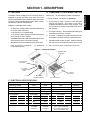
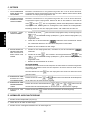
4. Crumb trays (3)
5. Conveyor
end trays (2)
6. Conveyor
7. Adjustable draft
curtains (2)
3. MenuSelect
®
keypad and display
2. Conveyor
reversing
switch
1. Power On/Off
(I/O) switch
8. Fan
SECTION 1 - DESCRIPTION
A. FEATURES
The Model TCO2114 Mighty Chef Conveyor Oven is
designed to quickly and easily cook, bake, and broil a
variety of food products with consistent quality and results.
The oven is ideal for preparing pizza, garlic toast, cookies,
sandwiches, and other food products.
Features of the Mighty Chef include:
An electronic, programmable controller that allows up
to 5 preset menu selections
A cool exterior for increased safety
A 14 (356mm)-wide conveyor belt that can be easily
set to operate in either direction
Adjustable draft curtains that reduce draft into the oven
and prevent heat loss into the environment
Welded and reinforced stainless steel construction
Fast countertop installation - no additional
components required
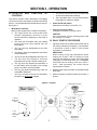
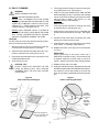
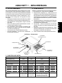
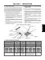
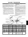
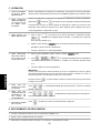
Figure 1 - Component location
B. COMPONENT LOCATION AND FUNCTION
Refer to Fig. 1 for the locations of these components.
1-3.Oven controls - see Section 3, Operation.
4. Crumb trays (3 total) - Collect crumbs that pass
through the conveyor. One center crumb tray is
located underneath the center of the conveyor. One
end crumb tray is located underneath EACH end of
the conveyor.
5. Conveyor end trays - Provide additional loading/exit
space at the ends of the conveyor.
6. Conveyor - Transports the product through the oven,
and between the top and bottom heating elements.
7. Adjustable draft curtains (2 total) - Reduce draft into
the oven and prevent heat loss into the environment.
8. Fan - Cools the interior components of the oven.
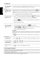
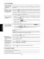
C. ELECTRICAL SPECIFICATIONS
TCO21140063 TCO21140066 TCO21140035 TCO21140077
Operating Voltage 208V 240V 230V 380-400V
Frequency 50/60 Hz 50/60 Hz 50 Hz 50 Hz
Phase 1 Ph 1 Ph 1 Ph 3 Ph
kW Rating 5.0kW 5.3kW 5.0kW 5.0kW
Current Draw 24.0A (total) 22.1A (total) 21.1A (total)
L1 N/A N/A N/A 0.3A
L2 N/A N/A N/A 10.5A
L3 N/A N/A N/A 10.3A
N N/A N/A N/A 10.3A
Cord/Plug Information
Attached cord Attached cord Kabelmetal-type HO7RN-F cord N/A
with NEMA with NEMA with 3 x 4.0mm conductors
6-30P plug 6-30P plug and moulded-on IEC 309 plug
Plug is rated 230VAC, 32A

ENGLISH
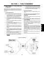
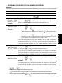
4
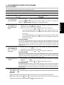
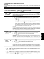
Equipotential ground
lug and symbol
(European ovens)
Cable clamp
Terminal
block
Connector
(3-phase ovens only)
Wiring
connections
(3-phase ovens
only)
SECTION 2 - INSTALLATION
IMPORTANT
IT IS THE
CUSTOMERS RESPONSIBILITY TO REPORT ANY
CONCEALED OR NON-CONCEALED DAMAGE TO THE
FREIGHT COMPANY.
A. INSTALLATION OPTIONS & KIT AVAILABILITY
If the installation will require two or three ovens to be stacked,
you must use the separately-available Stacking Kit (P/N
T2114STACK). One Kit is required for a two-stack, while two
kits are required for a three-stack.
Stacking more than three
ovens is not permitted.
Wherever the Stacking Kits instructions are different from those
listed below, follow the instructions provided with the Kit.
B. ASSEMBLY
1. Installing the Legs
a. Carefully tilt the oven onto its rear side. The front
(controller) side should be facing directly upwards.
b. Thread the four legs into the holes provided on the
bottom of the oven. Tighten them until they are secure.
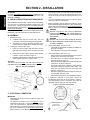
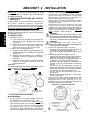
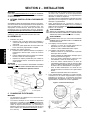
2. Installing the Conveyor End Trays
a. Press one of the conveyor end trays down over the
end plate of the conveyor frame, as shown in Figure
2.
b. Fasten the end tray in place with one of the supplied
8-32x3/8 screws, as shown in Figure 2.
c. Repeat the above steps to install the second end tray
at the opposite end of the conveyor frame.
CAUTION
THE SUPPLIED LEGS
AND THE END TRAYS MUST BE
FASTENED IN PLACE BEFORE OPERATING THE OVEN.
The toasters power cord and plug provide an electrical
ground connection. A separate equipotential ground con-
nection must also be made if required by national or local
codes.
Consult all applicable national and local codes for further
electrical connection requirements.
1. Before proceeding with the electrical connection, check
that the electrical supply matches the ovens requirements.
Refer to the serial plate and to the
Electrical Specifications
table (in Section 1 of this Manual).
WARNING
ENSURE THAT
BOTH THE CIRCUIT BREAKER/
FUSED DISCONNECT
AND THE POWER ON/OFF (I/
O) SWITCH ARE IN THE O (OFF) POSITION BEFORE
PROCEEDING.
WARNING
ENSURE THAT ANY PACKING MATERIAL RESIDUE
HAS BEEN REMOVED FROM INSIDE THE OVENS
COOKING CHAMBER.
2. Single-phase Mighty Chef ovens only:
Check that the appropriate receptacle is available for
the power cord plug.
Insert the power cord plug into its receptacle.
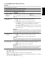
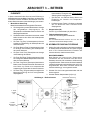
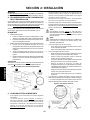
3. Three-phase Mighty Chef ovens only:
Remove the two screws that hold the rear cover panel
in place; then, remove the cover panel.
Insert the end of the electrical supply through the
connector shown in Figure 3.
Attach the electrical supply wires to their terminal block
connections, as shown in Figure 3.
Secure the supply wires to the floor of the electrical
compartment using the supplied cable clamp. The
wires must not interfere with the drive chain and
sprocket. See Figure 3.
Secure the supply as it passes through the connector
on the outside wall of the oven.
Replace the rear wall of the oven and fasten it in place.
4. If required by national or local codes, connect an
equipotential ground wire to the lug shown in Figure 3.
The equipotential ground connection must meet all
applicable national and local code requirements.
C. ELECTRICAL CONNECTION
IMPORTANT
Wiring diagrams for the oven are provided on pages 9-10
of this Manual.
The electrical connection to the oven
requires a circuit
breaker/fused disconnect. Consult applicable national and
local code requirements to determine the rating of the
breaker/disconnect. Electrical specifications are listed on
the ovens serial plate and in the
Electrical Specifications
table (in Section 1 of this Manual).
Figure 2 - End Tray Installation
Position tray
1
Fasten in
place
with screw
2
Repeat for
second tray
3
Figure 3 - Electrical Connections

ENGLISH
5
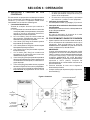
A. LOCATION AND FUNCTION OF
CONTROLS
This section provides a basic description of the Mighty
Chef ovens controls, their location, and the functions they
perform. The operator MUST be familiar with the controls.
See Figure 4.
1. MenuSelect
®
controller
Multi-function keypad which contains the following:
a. The display shows the current preset menu
selection, temperatures, cook time, or error/
service information, depending on the mode of
operation.
b. The ready light illuminates when both heating
zones of the oven have reached their set
temperatures.
c. The Top Temp key displays/sets the top zone
temperature.
d. The Bottom Temp key displays/sets the bottom
zone temperature.
e. The Cook Time key displays/sets the cook time.
f. The Ref Temp key displays a reference
temperature for the top or bottom heating zone.
g. The Sngl Pizza key adjusts the temperature of
the top heating zone to properly cook a single
pizza, or the last of a group of pizzas.
h. The Prog key allows reprogramming of the five
Preset Menu Selections.
i. The Prog Override key allows a Preset Menu
Program to be
temporarily changed.
Figure 4 - Controls
3. Con-
veyor
reversing
switch
2. Power
On/Off (I/O)
switch
j. The Up Arrow and Down Arrow keys are used to edit
cook time and temperature settings.
k. The Preset Menu keys (1-5) are used to select a
Preset Menu to change or operate.
2. Power On/Off (I/O) switch
Switches the oven ON (I) and OFF (O).
3. Conveyor reversing switch
Changes the direction of conveyor travel.
CAUTION
Do not operate the conveyor reversing switch while
the conveyor is in motion.
B. DAILY STARTUP PROCEDURE
1. Adjust the position of the draft curtains at the ends of
the cooking chamber (if necessary). This procedure
is described in detail in Part G, Draft Curtain
Adjustment, in this Section.
IMPORTANT
When cooking at very high temperatures (either
heating zone is 400°F / 204°C or higher), the oven
should be pre-heated for at least 10 minutes WITH
THE DRAFT CURTAINS IN THE FULLY-LOWERED
POSITION and both heating zones set to 599°F /
315°C. After pre-heating, the curtains may be
repositioned as required.
2. Restore power to the oven at the circuit breaker/fused
disconnect.
3. Switch the Power On/Off (I/O) Switch to the ON (I)
position.
e
d
c
f
i
k
b
a
j
h
g
SECTION 3 - OPERATION
1. MenuSelect
®
controller

ENGLISH
6
C. OPERATION
1. TO PROGRAM A
NEW PRESET MENU
SELECTION:
Perform the procedure in Part E, Programming Preset Menu Selections, in this Section. At least
one menu selection MUST be programmed before the oven can be operated.
Perform the procedure in Part E, Programming Preset Menu Selections, BUT press
instead
of
(in Steps 3 and 8). Instead of permanently overwriting the menu selection, the new set
temperature and cook time settings are only temporary. To cancel the temporary menu selection,
press any preset menu key or disconnect electrical power to the oven.
2. TO TEMPORARILY
OVERRIDE A PRE-
SET MENU SELEC-
TION:
a. Press
(or any other preset menu key). The display will read . The number
in the display (1 is shown above) will match the menu key that was pressed (1-5).
b. Wait for the
light to illuminate. The light will illuminate after both heating zones
reach their set temperatures.
c. Load the product onto the conveyor.
3. TO CHOOSE A PRE-
SET MENU SELEC-
TION:
a. Choose a preset menu selection, and wait for the
light to illuminate.
b. Press
. and will alternate in the display. The number in the
display (1 is shown above) will match the current menu selection (1-5).
c. Load the pizza product onto the conveyor.
IMPORTANT
After 1/2 of the cook time has elapsed, the temperature of the top zone will be automatically
lowered. After the entire cook time has elapsed, the program will return to its normal top zone
temperature.
After
is pressed, the menu selection cannot be changed until the cook time has elapsed.
4. TO COOK A SINGLE
PIZZA, OR THE LAST
OF A GROUP OF PIZ-
ZAS:
5. TO VIEW THE SET
TEMPERATURES:
6. TO VIEW HEATING
ZONE REFERENCE
TEMPERATURES:
Press either
or . The top or bottom set temperature will be displayed for 5 seconds.
D. SHUTDOWN PROCEDURE
1. Switch the Power On/Off (I/O) switch to the OFF (O) position.
2. Wait for the ovens cooling fan to turn off.
3. Disconnect electrical power to the oven at the circuit breaker/fused disconnect.
7. TO VIEW THE COOK
TIME:
Press
+ or + . The top or bottom reference temperature will be displayed
for 5 seconds.
Press
. The cook time will be displayed for 5 seconds.

ENGLISH
7
IMPORTANT
Adding a menu program to the oven will overwrite an existing program. DO NOT enter a new menu program over an
existing program that you wish to keep!
1. Restore power to the oven at the circuit breaker/fused disconnect.
2. Switch the Power On/Off (I/O) Switch to the ON (I) position.
E. PROGRAMMING PRESET MENU SELECTIONS
4. CHOOSE A MENU
SELECTION TO
PROGRAM
Press and hold (or any other preset menu key) until appears in the display and
begins to flash. The number in the display (1 is shown above) will match the menu key that was
pressed (1-5).
5. SET TOP TEM-
PERATURE
6. SET BOTTOM TEM-
PERATURE
a. Press . The current top set temperature appears in the display.
b. Press
and as necessary to change the displayed temperature.
Pressing
once increases the active (flashing) digit by one. This digit rolls over to
its minimum value if
is pressed when the digit shows its maximum value.
Pressing
once causes the next digit to the right to become the active (flashing)
digit. If the far-right digit is flashing when
is pressed, the far-left digit will flash and
become the active digit.
IMPORTANT
The allowed temperature range is 200-599°F (93-315°C). If you program a set temperature be-
tween 0°F (or 0°C) and 99°F (37°C), the heater will be set to OFF. If you program a set tempera-
ture between 100°F (38°C) and 199°F (92°C), the temperature will automatically change to 200°F
(93°C), the display will flash, and a beep will sound to alert you to the temperature change.
a. Press
. The current bottom set temperature appears in the display.
b. Press
and as necessary to change the displayed temperature.
IMPORTANT
Unless you are following specific time and temperature instructions, the top and bottom zone
temperatures should be set WITHIN 50°F (28°C) of each other. Greater temperature differences
may cause the hotter zone to heat the cooler zone. This can cause inconsistent cooking results.
a. Press
. The current cook time appears in the display (minutes : seconds).
b. Press
and as necessary to change the displayed time.
IMPORTANT
The allowed cook time range is 00:30-15:00. If you program a cook time outside of this range, the
time will change to the closest allowed time (00:30 if your time was too short, or 15:00 if it was too
long). The display will flash, and a beep will sound to alert you to the changed cook time.
8. Press ONE of the following keys:
, , or : Re-enter the top setpoint temperature, bottom set point temperature, or cook time.
: Turn off Programming Mode. This returns the oven to normal operation.
Any other key except
or : Resume operation, but leave Programming Mode active. Other Preset
Menu Selections can be programmed at this time.
3. Press and hold
until appears in the display.
7. SET COOK TIME

ENGLISH
8
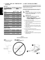
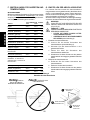
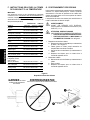
Figure 5
Repositioning the draft curtains
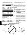
G. DRAFT CURTAIN ADJUSTMENT
The draft curtains may need to be repositioned to provide
adequate clearance for some food products. The curtains
should be positioned to prevent drafts into the oven, and
heat loss into the environment.
The draft curtains can be removed from the oven to permit
the maximum vertical clearance above the conveyor.
WARNING
BEFORE ADJUSTING THE DRAFT CURTAINS,
SWITCH THE POWER ON/OFF (I/O) SWITCH
TO THE OFF (O) POSITION.
CAUTION - HOT
WHEN REPOSITIONING THE CURTAINS:
WEAR A HEAVY OVEN MITT.
DO NOT REACH INTO THE OVENS
COOKING CHAMBER! See Figure 5.
1. To reposition the draft curtains:
a. Loosen the two screws that hold the draft curtain
in place. See Figure 5.
b. Slide the curtain to the desired clearance above
the conveyor.
c. Tighten the two screws to hold the curtain in place.
d. Repeat these steps for the curtain at the opposite
end of the oven.
2. To remove the curtains from the oven:
a. Remove the two screws that hold the draft curtain
in place.
b. Remove the draft curtain.
c. Repeat these steps for the curtain at the opposite
end of the oven.
Loosen
screws
1
Tighten
screws
3
DO keep hands outside
of cooking chamber
DO NOT reach inside
cooking chamber
2
Reposition
curtain
F. COOKING TIME AND TEMPERATURE
GUIDELINES
IMPORTANT
The cooking times and temperatures shown below are
recommendations only. You should always test each
food product to determine correct time and temperature
settings.
SET TEMPERATURE COOK
PRODUCT upper lower TIME
Bagel Bites 400°F/204°C 420°F/216°C 5:00
Biscuits 250°F/121°C 335°F/168°C 6:45
Bread Sticks (retherm) 425°F/218°C 475°F/246°C 4:30
Cheese Sticks (frozen) 460°F/238°C 445°F/229°C 6:00
Chicken Nuggets (frozen) 460°F/238°C 445°F/229°C 6:00
Cookies 375°F/191°C 375°F/191°C 9:00
Garlic Bread (retherm) 425°F/218°C 475°F/246°C 2:30
Hamburgers (frozen) 540°F/282°C 540°F/282°C 5:00
Jalapeno Poppers 460°F/238°C 400°F/204°C 6:45
Pizza (fresh), 12 (300mm) dia. 375°F/191°C 480°F/249°C 6:30
Pizza (retherm), slice 425°F/218°C 500°F/260°C 2:15
Pizza (frozen - slacked in
refrigerator 12 hrs. before
cooking), 6-8(150-200mm) dia. 380°F/193°C 430°F/221°C 6:30
Pizza, par baked crust 470°F/243°C 525°F/274°C 6:30
Pretzels (pre-cooked) 505°F/263°C 540°F/282°C 0:45
Sandwiches, open-faced 550°F/288°C 550°F/288°C 0:50

ENGLISH
9
H. DAILY CLEANING
WARNING
WHEN CLEANING THE OVEN:
NEVER USE PRESSURIZED WATER.
NEVER USE A CLEANING SOLUTION OTHER
THAN SOAP AND WATER ON PORTIONS OF THE
OVEN THAT COME INTO CONTACT WITH FOOD
PRODUCTS. THESE AREAS INCLUDE THE
CONVEYOR BELT AND END TRAYS.
NEVER APPLY ENOUGH LIQUID TO STAND IN
PLACE ON THE OVEN. LIQUID INSIDE THE OVEN
WILL CAUSE A SEVERE ELECTRICAL HAZARD
AND MAY OTHERWISE DAMAGE THE OVEN.
CAUTION
DO NOT clean your oven using abrasive cleaners or pads.
Both will scratch and dull the finish.
1. With the conveyor running, use a brush to clean any
crumbs off the conveyor into the crumb trays.
2. Switch the Power On/Off (I/O) switch to the OFF (O)
position, and wait for the cooling fan to turn off.
3. Disconnect electrical power to the oven at the circuit
breaker/fused disconnect.
4. Allow the oven to cool.
CAUTION - HOT
DO NOT TOUCH HOT SURFACES ON THE
OVEN, OR REACH INTO THE COOKING
CHAMBER, UNTIL THE UNIT HAS COOLED
THOROUGHLY.
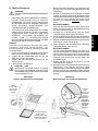
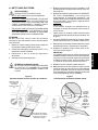
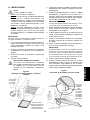
5. Thoroughly clean the fan grill on the front of the oven
using a stiff nylon brush. See Figure 6.
6. Clean the end trays USING SOAP AND WATER
ONLY and towel them dry. If necessary, the end trays
can be removed for cleaning by removing the screws
that hold them in place. See Figure 2 (in the
Installation section of this Manual).
IMPORTANT
If the end trays are removed for cleaning, they must
be replaced prior to operating the oven.
7. Slide the end crumb trays out from underneath the
entrance and exit ends of the conveyor. See Figure
6.
8. Lift BOTH ends of the center crumb tray; then, slide
the tray out of either end of the oven.
9. Clean all three of the crumb trays using a commercial
oven cleaner. If necessary, towel them dry.
10. Replace the center crumb tray in the oven as shown
in Figure 7.
IMPORTANT
Proper positioning of the center crumb tray is
REQUIRED for proper cooking. Ensure that the tray
is replaced inside the conveyor frame, as shown in
Figure 7, and NOT on the floor of the cooking chamber!
11. Replace the two end crumb trays.
12. Clean the outside of the oven using a damp cloth with
EITHER soap and water OR a stainless steel cleaner.
Use caution to ensure that liquids do not enter the
oven during cleaning, especially when wiping the fan
grill.
Figure 6
End crumb trays and fan grill
Figure 7
Center crumb tray placement
Slide trays straight out
(trays are underneath both
ends of conveyor)
Tray fits
BETWEEN
conveyor belt
and support
tab.
DO NOT
insert tray
on floor of
oven!
Conveyor
belt
Support
tab
Clean fan grill
using stiff
nylon brush

ENGLISH
10
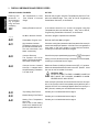
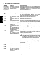
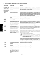
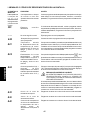
I. DISPLAY MESSAGES AND ERROR CODES
DISPLAY SHOWS PROBLEM ACTION
Re-enter the program using Set Temperatures and Cook Time
within the allowed range. Also, refer to Part E, Programming
Preset Menu Selections, in this Section.
If the element should be on, re-enter the program using Set
Temperatures within the allowed range. Also, refer to Part E,
Programming Preset Menu Selections, in this Section.
Choose or program a preset menu selection.
Re-enter the Preset Menu program.
Check the cooling fan (centered on the front panel of the oven) for
cleanliness and proper operation. If the fan is not running after the
oven heats, or the oven remains in a high ambient condition,
contact your local Authorized Service Agent.
Check for the proper speed setting by pressing
. If the speed
setting is correct, and the conveyor continues to run at full speed,
contact your Authorized Service Agent.
Switch the Power On/Off (I/O) Switch to the OFF (O) position.
Switch the breaker/fused disconnect to the OFF position. Allow
the oven to cool for at least 30 minutes.
CAUTION - HOT
DO NOT ATTEMPT TO FREE A JAMMED CONVEYOR
BELT WHILE THE COOKING CHAMBER IS WARM.
SEVERE INJURY MAY RESULT.
If the conveyor is jammed, free the obstruction from the conveyor
belt. If the conveyor still will not operate properly after the jam is
cleared, OR if the error message appears when the conveyor is
NOT jammed, contact your local authorized service agent.
Contact your local authorized service agent.
Contact your local authorized service agent.
Contact your local authorized service agent.
Flashing tem-
peratures or
cook times dur-
ing program-
ming, and oven
is beeping
OFF
- - - -
E-00
E-01
E-02
E-04
E-35
E-36
E-40
Set Temperatures or Cook
Time Outside of Allowed
Range
Heating Element turned off
No Menu Selection Chosen
Preset Menu Program Lost
High Ambient Condition
Temperature inside the con-
trol enclosure exceeds 65°C.
The oven shuts down, then
beeps continuously.
Conveyor Runaway
The conveyor runs at full
speed. The oven shuts down,
then beeps continuously.
Top Heating Zone Failure
Bottom Heating Zone Failure
Conveyor Loose or Jammed
Conveyor is stopped when
the speed setting is between
0:15 and 15:00.
Heating Zone Temperature
High Limit
One or both of the heating
zones have reached a tem-
perature greater than 315°C.

ENGLISH
11
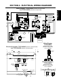
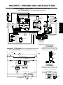
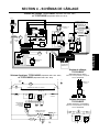
SECTION 4 - ELECTRICAL WIRING DIAGRAMS
Wiring Diagram, TCO21140063 (Domestic & Std. Export 208V)
and TCO21140066 (Domestic & Std. Export 240V)
TOP HEATER
BOTTOM HEATER
TC
SSR 1
SSR 2
MENUSELECT
®
CONTROLLER
TFRMR
230Vp
115Vs
TFRMR
230Vp
12Vs
FUSE
0.5A
TSTAT
CONTACTOR
MOTOR
FUSE
0.25A
PICKUP ASSY
CONVEYOR
REVERSING SWITCH
POWER ON/OFF
(I/O) SWITCH
FAN
CC FUSES (2)
5.0A/600V
VAR
VAR
N.C.
TSTAT
N.O.
TC
EL1
RFI
FILTER
N
BLACK
WHITE
RED
Electrical Schematic, TCO21140063 (Domestic & Std. Export 208V)
and TCO21140066 (Domestic & Std. Export 240V)
FAN
TSTAT
N.O.
TSTAT
N.C.
POWER ON/OFF (I/O) SWITCH 2 POLE
C
L1
C2
C1
230Vp
115Vs
230Vp
12Vs
0.5A
SSR 1
SSR 2
M
0.25A
CONVEYOR
REVERSING
SWITCH
SSR 1 SSR 2
TOP HEATER 2500W
BOTTOM HEATER 2500W
NE
MENUSELECT
®
CONTROLLER
CC FUSE
5.0A/600V
CC FUSE
5.0A/600V
CC FUSES (2)
5.0A/600V
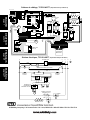
Wiring Diagram,
TCO21140035
(European Export 230V)
Remainder of wiring matches
TCO21140063/0066
Electrical Schematic,
TCO21140035
(European Export 230V)
Remainder of wiring matches
TCO21140063/0066
230Vp
115Vs
230Vp
12Vs
0.5A
RFI FILTER

ENGLISH FRANÇAIS ESPAÑOL
page 1 page 25 página 37
DEUTSCH
seite 13
TOP HEATER
BOTTOM HEATER
TC
SSR 1
SSR 2
MENUSELECT
®
CONTROLLER
TFRMR
230Vp
115Vs
TFRMR
230Vp
12Vs
FUSE
0.5A
TSTAT
CONTACTOR
MOTOR
FUSE
0.25A
PICKUP ASSY
CONVEYOR
REVERSING SWITCH
POWER ON/OFF
(I/O) SWITCH
FAN
CC FUSES (2)
5.0A/600V
VAR
VAR
N.C.
TSTAT
N.O.
TC
L2NL1 E
LINE
FILTER
RFI
FILTER
L3
BLACK
WHITE
RED
A Middleby Company 10 Sunnen Drive St. Louis, MO 63143 800.807.9054 FAX 314.781.2714
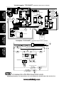
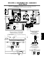
Wiring Diagram, TCO21140077 (European Export 380-400V)
Electrical Schematic, TCO21140077 (European Export 380-400V)
FAN
TSTAT
N.O.
TSTAT
N.C.
POWER ON/OFF (I/O) SWITCH 2 POLE
C
L2
N
C1
C2
230Vp
115Vs
230Vp
12Vs
0.5A
SSR 1
SSR 2
M
0.25A
CONVEYOR
REVERSING
SWITCH
SSR 1 SSR 2
TOP HEATER 2500W
BOTTOM HEATER 2500W
C3 C4
L1 L3 E
RFI FILTER
MENUSELECT
®
CONTROLLER
LINE FILTER
CC FUSE
5.0A/600V
CC FUSE
5.0A/600V

ENGLISHFRANÇAISESPAÑOL
page 1page 25página 37
DEUTSCH
Seite 13
$0LGGOHE\&RPSDQ\6XQQHQ'ULYH6W/RXLV02 )$;
TM

14
A Middleby Company
10 Sunnen Drive
St. Louis, MO 63143
800.807.9054
FAX 314.781.2714
INHALT
ABSCHNITT 1
BESCHREIBUNG .......................................15
A. Produktmerkmale ............................................15
B. Komponenten..................................................15
C. Elektrische Daten ...........................................15
ABSCHNITT 2
INSTALLATION ........................................... 16
A. Installationsoptionen und verfügbare Kits ........16
B. Zusammenbau ................................................ 16
C. Elektrischer Anschluss ...................................16
ABSCHNITT 3
BETRIEB ..................................................... 17
A. Lage und Funktion der Bedienelemente .......... 17
B. Normaler Einschaltvorgang .............................17
C. Betrieb ............................................................ 18
D. Normaler Ausschaltvorgang ............................18
E. Programmieren eigener Garprogramme ...........19
F. Empfehlungen für Garzeiten und
Temperaturen ..................................................20
G. Einstellen der Abschlussbleche ...................... 20
H. Tägliche Reinigung ..........................................21
I. Meldungen und Fehlercodes ........................... 22
ABSCHNITT 4
VERKABELUNGS- UND SCHALTPLÄNE . 23
A. Verkabelungs- und Schaltplan:
TCO21140063 (US- und Standard-Export-
Version, 208V) und TCO21140066
(US- und Standard-Export-Version, 240V) ....... 23
B. Verkabelungs- und Schaltplan:
TCO21140035 (Europäische Export-
Version, 230V) ................................................23
C. Verkabelungs- und Schaltplan:
TCO21140077 (Europäische Export-
Version, 380-400V) ......................................... 24

15
DEUTSCH
4. Krümelbleche (3)
5. Förderband-
endbleche (2)
6. Förderband
7. Einstellbare
Abschlussbleche (2)
3. MenuSelect
®
-
Tastenfeld und
Anzeige
2. Förderband-
umkehrschalter
1. Hauptschalter (I/O)
8. Lüfter
ABSCHNITT 1 - BESCHREIBUNG
A. PRODUKTMERKMALE
Der Förderbandofen Modell TCO2114 Mighty Chef wurde
für das schnelle und einfache Garen, Backen und Grillen
einer Vielzahl von Gerichten mit gleichbleibender Qualität
entwickelt. Der Ofen eignet sich ideal für die Zubereitung
von Pizza, Knoblauchbrot, Cookies, Sandwiches u.v.a.m.
Der Mighty Chef verfügt über die folgenden Produkt-
merkmale:
Die programmierbare elektronische Steuerung erlaubt
die Auswahl von fünf verschiedenen Garprogrammen.
Das hitzeisolierte Außengehäuse sorgt für erhöhte
Sicherheit.
Das 14 Zoll (356mm) breite Förderband kann in beiden
Laufrichtungen betrieben werden.
Die einstellbaren Abschlussbleche reduzieren das
Eindringen von Zugluft in den Ofen sowie die Abgabe
von Hitze an die Umgebung.
Verschweißte und verstärkte Stahlkonstruktion
Schnelle Installation - es sind keine zusätzlichen
Komponenten erforderlich.
Abbildung 1 - Komponenten
B. KOMPONENTEN
Abbildung 1 zeigt die Position der einzelnen Komponenten.
1-3. Ofen-Steuerung - siehe Abschnitt 3, Betrieb.
4. Krümelbleche (insgesamt 3) - Diese dienen zum
Auffangen der durch das Förderband fallenden Krümel.
Ein zentrales Krümelblech befindet sich unterhalb des
Förderbandes in der Ofenkammer. An BEIDEN Enden
des Förderbandes befindet sich jeweils ein weiteres
Krümelblech.
5. Förderbandendbleche - Diese bieten an den Enden des
Förderbandes zusätzliche Arbeitsflächen für das Be-
und Entladen des Förderbandes.
6. Förderband - Dieses transportiert die Gerichte
zwischen den oberen und unteren Heizelementen durch
den Ofen.
7. Einstellbare Abschlussbleche (insgesamt 2) - Diese
reduzieren das Eindringen von Zugluft in den Ofen sowie
die Abgabe von Hitze an die Umgebung.
8. Lüfter - Kühlt die internen Komponenten des Ofens.
C. ELEKTRISCHE DATEN
TCO21140063 TCO21140066 TCO21140035 TCO21140077
Betriebsspannung 208V 240V 230V 380-400V
Netzfrequenz 50/60Hz 50/60Hz 50Hz 50Hz
Phasen einphasig einphasig einphasig dreiphasig
Anschlusswert 5,0 kW 5,3 kW 5,0 kW 5,0 kW
Strombedarf 24,0 A (gesamt) 22,1 A (gesamt) 21,1 A (gesamt)
L1 Nicht belegt Nicht belegt Nicht belegt 0,3 A
L2 Nicht belegt Nicht belegt Nicht belegt 10,5 A
L3 Nicht belegt Nicht belegt Nicht belegt 10,3 A
N Nicht belegt Nicht belegt Nicht belegt 10,3 A
Informationen zu Kabel und
Fest angeschlosse- Fest angeschlosse- Kabelmetal HO7RN-F-Kabel mit Nicht belegt
Stecker nes Kabel mit NEMA- nes Kabel mit NEMA- drei 4,0-mm-Leitern und angegos-
6-30P-Stecker 6-30P-Stecker senem IEC 309-Stecker, Stecker-
klassifizierung: 230VAC, 32A

16
DEUTSCH
Erdungsanschluss
und -symbol (nur bei
europäischer Export-
Version)
Kabelschelle
Anschlussblock
Kabeldurchführung (nur
dreiphasig betriebene Öfen)
Zuleitungs-
anschlüsse
(nur dreiphasig betrie-
bene Öfen)
ABSCHNITT 2 - INSTALLATION
Wichtiger Hinweis
DER
KUNDE IST DAFÜR VERANTWORTLICH, DEM
FRACHTFÜHRER SICHTBARE UND VERBORGENE
SCHÄDEN ZU MELDEN.
A. INSTALLATIONSOPTIONEN UND VERFÜG-
BARE KITS
Für die Installation von zwei oder drei Öfen übereinander ist
das separat erhältliche Stapel-Kit (Teilenummer
T2114STACK) erforderlich. Bei einem Doppel-Ofen benötigen
Sie ein Kit, bei einem Dreifach-Ofen zwei Kits.
Es dürfen
maximal drei Öfen übereinander installiert werden.
Wo die dem Stapel-Kit beiliegenden Anweisungen von den
folgenden Anweisungen abweichen, haben die Anweisungen
des Stapel-Kits Vorrang.
B. AUFSTELLUNG
1. Installation der Füße
a. Legen Sie den Ofen vorsichtig auf die Rückseite. Die
Vorderseite (mit den Bedienelementen) sollte nach
oben weisen.
b. Schrauben Sie die vier Füße an der Unterseite des
Ofens in den dafür vorgesehenen Löchern fest.
Ziehen Sie diese fest an, bis sie sicher sitzen.
2. Installation der Förderbandendbleche
a. Hängen Sie wie in Abbildung 2 dargestellt eines der
Förderbandendbleche in das Ende des Förderband-
rahmens ein.
b. Befestigen Sie das Endblech wie in Abbildung 2
dargestellt mit einer der mitgelieferten 8-32x3/8'-
Schrauben.
c. Wiederholen Sie die Schritte a und b mit dem zweiten
Endblech am entgegen gesetzten Ende des
Förderbandrahmens.
VORSICHT
VOR INBETRIEBNAHME DES OFENS
MÜSSEN DIE FÜßE
UND DIE ENDBLECHE MONTIERT WERDEN.
sowie in der Tabelle
Elektrische Daten in
Abschnitt 1 dieses Handbuchs.
Der Ofen wird über das Netzkabel und den Netzstecker
geerdet. Sofern aufgrund nationaler oder regionaler
Bestimmungen erforderlich muss außerdem eine
separate Erdverbindung hergestellt werden.
Sofern nationale oder regionale Bestimmungen weitere
Anforderungen an den elektrischen Anschluss stellen,
sind diese zu erfüllen.
1. Kontrollieren Sie, dass die Stromversorgung den
Anforderungen des Ofens (Spannung, Leistung)
entspricht, bevor Sie mit dem elektrischen Anschluss
fortfahren. Die entsprechenden Informationen finden Sie
auf dem Typenschild sowie in der Tabelle
Elektrische
Daten in Abschnitt 1 dieses Handbuchs.
WARNUNG
VERGEWISSERN SIE SICH, DASS SOWOHL DER
LEISTUNGS-SCHUTZSCHALTER/DIE SICHERUNG ALS
AUCH DER HAUPTSCHALTER (I/O) AUSGESCHALTET
(STELLUNG O) SIND, BEVOR SIE FORTFAHREN.
WARNUNG
VERGEWISSERN SIE SICH, DASS ALLE
VERPACKUNGSRESTE AUS DER GARKAMMER DES
OFENS ENTFERNT WURDEN.
2. Bei einphasig betriebenen Mighty Chef-Öfen:
Stellen Sie sicher, dass eine geeignete Steckdose für
den Stecker des Netzkabels vorhanden ist.
Führen Sie den Stecker des Netzkabel in die Steckdose
ein.
3. Bei dreiphasig betriebenen Mighty Chef-Öfen:
Entfernen Sie die beiden Schrauben der rückseitigen
Abdeckung. Entfernen Sie dann die Abdeckung.
Führen Sie das Ende des Anschlusskabels durch die
in Abbildung 3 dargestellte Kabeldurchführung.
Schließen Sie wie in Abbildung 3 dargestellt die
einzelnen Leiter des Anschlusskabels am Anschluss-
block an.
Fixieren Sie das Anschlusskabel mit Hilfe der
mitgelieferten Kabelschelle am Ofenboden. Achten Sie
darauf, dass das Kabel nicht zwischen Antriebsritzel
und -kette geraten kann (siehe Abbildung 3).
Fixieren Sie das Anschlusskabel in der Kabel-
durchführung.
Bringen Sie die Abdeckung wieder an, und schrauben
Sie diese wieder fest.
4. Sollten nationale oder regionale Bestimmungen dies
erfordern, so schließen Sie eine Erdleitung an den
Erdungsanschluss (siehe Abbildung 3) an. Die
Erdverbindung muss allen zutreffenden nationalen und
regionalen Anforderungen entsprechen.
C. ELEKTRISCHER ANSCHLUSS
WICHTIGER HINWEIS
Auf den Seiten 23 und 24 dieses Handbuchs finden Sie
die Verkabelungs- und Schaltpläne für den Ofen.
Der elektrische Anschluss des Ofens
muss über
Leistungsschutzschalter oder Sicherungen abgesichert
sein. Die Dimensionierung des Schutzschalters/der
Sicherungen ergibt sich aus den anwendbaren
nationalen und lokalen Bestimmungen. Die elektrischen
Anschlusswerte finden Sie auf dem Typenschild des Ofens
Abbildung 2 - Montage der Endbleche
Abbildung 3 - Elektrischer Anschluss
Bringen Sie das
Blech an
1
Schrauben Sie
das Blech
fest
2
Verfahren Sie ebenso
mit dem zweiten Blech
3

17
DEUTSCH
A. LAGE UND FUNKTION DER BEDIEN-
ELEMENTE
In diesem Abschnitt finden Sie eine kurze Einführung in
die Bedienelemente des Mighty Chef-Ofens, wo diese liegen
und welche Funktion sie haben. Der Bediener muss mit
diesen Steuerelementen (siehe Abbildung 4) vertraut sein.
1. MenuSelect
®
-Steuerung
Multifunktionstastenfeld mit folgenden Elementen:
a. Die Anzeige dient je nach Betriebsart zur Anzeige
des ausgewählten Garprogramms, der
Temperaturen und Garzeiten sowie von Fehler- und
Wartungsinformationen.
b. Die Bereitschafts-Kontrollleuchte leuchtet, sobald
beide Heizzonen des Ofens die Solltemperatur
erreicht haben.
c. Die Taste Top Temp (Obertemperatur) dient zur
Anzeige und Einstellung der Solltemperatur der
oberen Heizzone.
d. Die Taste Bottom Temp (Untertemperatur) dient
zur Anzeige und Einstellung der Solltemperatur
der unteren Heizzone.
e. Die Taste Cook Time (Garzeit) dient zur Anzeige
und Einstellung der Garzeit.
f. Die Taste Ref Temp (Referenztemperatur) dient
zur Anzeige einer Referenztemperatur für die obere
oder die untere Heizzone.
g. Die Taste Sngl Pizza (Einzelpizza) bewirkt beim
Backen einer einzelnen Pizza oder der letzten aus
einer Reihe von Pizzen eine entsprechende
Anpassung der Temperatur der oberen Heizzone.
h. Die Taste Prog (Programmieren) ermöglicht eine
Neuprogrammierung der fünf voreingestellten
Garprogramme.
Abbildung 4 Bedienelemente
3. Förder-
bandumkehr-
schalter
2. Haupt-
schalter
(I/O)
i. Die Taste Prog Override (Programmierung
überschreiben) ermöglicht die
vorübergehende
Änderung eines Garprogramms.
j. Die Pfeil-Auf- und Pfeil-Ab-Tasten dienen zum
Einstellen der Garzeit und Temperatur-
einstellungen.
k. Die Garprogramm-Tasten (1-5) dienen zur Auswahl
des zu ändernden oder auszuführenden
Garprogramms.
2. Hauptschalter (I/O)
Zum Ein- (I) und Ausschalten (O) des Ofens.
3. Förderbandumkehrschalter
Ändert die Laufrichtung des Förderbands.
VORSICHT
Der Förderbandumkehrschalter darf nur bei still
stehendem Förderband betätigt werden.
B. NORMALER EINSCHALTVORGANG
1. Stellen Sie (sofern erforderlich) die Abschlussbleche
an beiden Enden der Garkammer ein. Dieser Vorgang
wird in Teil G dieses Abschnitts, Einstellen der
Abschlussbleche, detailliert beschrieben.
WICHTIGER HINWEIS
Beim Betrieb mit extrem hohen Temperaturen
(mindestens eine der Heizzonen wird über 200°C
betrieben) muss der Ofen mindestens 10 Minuten lang
vorgeheizt werden. Dabei müssen die Abschlussbleche
vollständig abgesenkt und beide Heizzonen auf 315°C
eingestellt sein. Nach dem Vorheizen können die
Abschlussbleche ggf. neu eingestellt werden.
2. Schalten Sie den Leistungsschutzschalter oder die
Sicherungen ein.
3. Schalten Sie den Hauptschalter (I/O) ein (I).
e
d
c
f
i
k
b
a
j
h
g
ABSCHNITT 3 BETRIEB
1. MenuSelect
®
-Steuerung

18
DEUTSCH
D. NORMALER AUSSCHALTVORGANG
1. Schalten Sie den Hauptschalter (I/O) aus (O).
2. Warten Sie, bis der Lüfter der Ofens stoppt.
3. Schalten Sie den Leistungsschutzschalter bzw. die Sicherungen aus.
C. BETRIEB
1. PROGRAMMIEREN
EINES NEUEN GAR-
PROGRAMMS:
Detaillierte Informationen zur Programmierung finden Sie in Teil E dieses Abschnitts,
Programmieren eigener Garprogramme. Bevor Sie den Ofen in Betrieb nehmen können, MUSS
mindestens ein Garprogramm programmiert sein.
Detaillierte Informationen zur Programmierung finden Sie in Teil E dieses Abschnitts,
Programmieren eigener Garprogramme. Drücken Sie aber in den Schritten 3 und 8 statt der
Taste
die Taste . Die neu eingestellte(n) Garzeit und Solltemperaturen ändern das
Garprogramm nicht, sondern gelten nur vorübergehend. Zum Aufheben der vorübergehenden
Einstellung drücken Sie eine der Garprogramm-Tasten, oder schalten Sie den Ofen aus.
2. VORÜBERGEHENDE
ÄNDERUNG EINES
GARPROGRAMMS:
a. Drücken Sie die Taste
(oder eine andere Garprogramm-Taste). Die Anzeige zeigt nun
. Die Ziffer in der Anzeige (im Beispiel 1) gibt an, welches Garprogramm (1-5)
ausgewählt wurde.
b. Warten Sie, bis die Kontrollleuchte
aufleuchtet. Diese Kontrollleuchte leuchtet
auf, sobald beide Heizzonen des Ofens die Solltemperatur erreicht haben.
c. Beladen Sie das Förderband mit dem Gargut.
3. AUSWAHL EINES
GARPROGRAMMS:
a. Drücken Sie eine Garprogramm-Taste, und warten Sie, bis die Kontrollleuchte
aufleuchtet.
b. Drücken Sie die Taste
. Nun erscheint in der Anzeige abwechselnd und
. Die Ziffer in der Anzeige (im Beispiel 1) gibt an, welches Garprogramm (1-5)
ausgewählt wurde.
c. Beladen Sie das Förderband mit der Pizza.
WICHTIGER HINWEIS
Nach Ablauf der halben Garzeit wird die Temperatur der oberen Heizzone automatisch abgesenkt.
Nach Ablauf der gesamten Garzeit wird die Temperatur der oberen Heizzone wieder auf den
Sollwert eingestellt.
Nach dem Drücken der Taste
kann das Garprogramm erst wieder nach Ablauf der Garzeit
geändert werden.
4. BACKEN EINER EIN-
ZELNEN PIZZA ODER
DER LETZTEN AUS
EINER REIHE VON
PIZZEN:
5. KONTROLLE DER
EINGESTELLTEN
SOLLTEMPERATUREN:
6. KONTROLLE DER
REFERENZTEMPERA-
TUREN:
7. KONTROLLE DER
GARZEIT:
Drücken Sie eine der Tasten
oder . Danach wird für fünf Sekunden die Solltemperatur
für die obere bzw. die untere Heizzone angezeigt.
Drücken Sie eine der Tastenkombinationen
+ oder + . Danach wird für
fünf Sekunden die Referenztemperatur für die obere bzw. die untere Heizzone angezeigt.
Drücken Sie die Taste
. Danach wird für fünf Sekunden die Garzeit angezeigt.

19
DEUTSCH
WICHTIGER HINWEIS
Bei der Programmierung eines neuen Programms wird das vorhandene Programm überschrieben. Achten Sie darauf, dass
Sie keine Programme überschreiben, die Sie behalten möchten.
1. Schalten Sie den Leistungsschutzschalter oder die Sicherungen ein.
2. Schalten Sie den Hauptschalter (I/O) ein (I).
E. PROGRAMMIEREN EIGENER GARPROGRAMME
4. AUSWÄHLEN DES
ZU ÄNDERNDEN
GARPROGRAMMS.
Halten Sie die Taste (oder eine andere Garprogramm-Taste) gedrückt, bis in der Anzeige
die Meldung
erscheint und zu blinken beginnt. Die Ziffer in der Anzeige (im
Beispiel 1) gibt an, welches Garprogramm (1-5) ausgewählt wurde.
5. EINSTELLEN DER
SOLLTEMPERATUR
DER OBEREN HEIZ-
ZONE
6. EINSTELLEN DER
SOLLTEMPERATUR
DER UNTEREN
HEIZZONE
a. Drücken Sie die Taste . Nun wird in der Anzeige die aktuelle Einstellung der
Solltemperatur für die obere Heizzone angezeigt.
b. Stellen Sie mit Hilfe der Tasten
und die gewünschte Temperatur ein.
Durch einmalige Betätigung der Taste
wird die aktive (blinkende) Ziffer um eins
erhöht. Hat die Ziffer den Wert 9, so wird sie beim erneuten Drücken der Taste wieder
auf 0 gesetzt.
Durch einmalige Betätigung der Taste
wird die nächste Ziffer rechts aktiviert. Blinkt
bereits die Ziffer der Einerstelle, so wird durch erneute Betätigung die Ziffer der
Hunderterstelle aktiviert.
WICHTIGER HINWEIS
Der zulässige Temperaturbereich ist 93°C bis 315°C. Wenn Sie eine Temperatur zwischen 0°C
und 37°C programmieren, wird die Heizzone deaktiviert. Bei Programmierung eines Wertes
zwischen 38°C und 92°C wird die Temperatur automatisch auf 93°C gesetzt. In diesem Fall
weisen Sie die blinkende Anzeige und ein Signalton auf die automatische Änderung der
Temperatur hin.
a. Drücken Sie die Taste
. Nun wird in der Anzeige die aktuelle Einstellung der
Solltemperatur für die untere Heizzone angezeigt.
b. Stellen Sie mit Hilfe der Tasten
und die gewünschte Temperatur ein.
WICHTIGER HINWEIS
Sofern Sie nicht spezielle Vorgaben für Garzeit und Temperaturen haben, sollten die eingestellten
Temperaturen für die obere und die untere Garzone maximal 28°C voneinander abweichen. Bei
größeren Temperaturunterschieden besteht die Gefahr, dass die heißere Zone die kühlere
aufheizt. Dies kann zu unregelmäßigen Garresultaten führen.
a. Drücken Sie die Taste
. Nun wird in der Anzeige die aktuelle Garzeit (Minuten : Sekunden)
angezeigt.
b. Stellen Sie mit Hilfe der Tasten
und die gewünschte Garzeit ein.
WICHTIGER HINWEIS
Die Garzeit muss in einem Bereich von 00:30 bis 15:00 liegen. Wenn Sie eine kürzere (längere)
Garzeit programmieren, wird automatisch der zulässige Mindestwert (Höchstwert) eingestellt. In
diesem Fall weisen Sie die blinkende Anzeige und ein Signalton auf die automatische Änderung
der Garzeit hin.
8. Drücken Sie EINE der folgenden Tasten:
, oder . : Erneute Programmierung der Solltemperatur für die obere oder die untere Heizzone oder
der Garzeit.
: Deaktivieren des Programmiermodus. Der Ofen kehrt in den normalen Betriebsmodus zurück.
Jede andere Taste außer
oder : Wiederaufnahme des Betriebs bei weiterhin aktiviertem
Programmiermodus. Nun können Sie weitere Garprogramme programmieren.
3. Halten Sie die Taste
gedrückt, bis in der Anzeige die Meldung erscheint.
7. EINSTELLEN DER
GARZEIT

20
DEUTSCH
Abbildung 5
Einstellen der Abschlussbleche
G. EINSTELLEN DER ABSCHLUSSBLECHE
Für manche Gerichte müssen die Abschlussbleche
möglicherweise neu eingestellt werden, damit diese durch
die Ein- und Auslassöffnung passen. Diese Abschluss-
bleche reduzieren das Eindringen von Zugluft in den Ofen
sowie die Abgabe von Hitze an die Umgebung.
Wird die maximal mögliche Höhe der Öffnungen benötigt,
so können die Abschlussbleche auch ganz entfernt werden.
WARNUNG
SCHALTEN SIE VOR DEM EINSTELLEN DER
ABSCHLUSSBLECHE DEN HAUPTSCHALTER
(I/O) AUS (O).
VORSICHT HEIß
VORSICHTSMAßNAHMEN BEIM EINSTELLEN
DER ABSCHLUSSBLECHE:
LEGEN SIE EINEN DICKEN HITZE-
SCHUTZHANDSCHUH AN..
GREIFEN SIE NICHT IN DIE GARKAMMER
DES OFENS (siehe Abbildung 5).
1. Einstellen der Abschlussbleche:
a. Lockern Sie die beiden Schrauben des
Abschlussblechs (siehe Abbildung 5).
b. Schieben Sie das Abschlussblech in die
gewünschte Position.
c. Ziehen Sie dann die Schrauben des
Abschlussblechs wieder fest.
d. Wiederholen Sie diese Schritte mit dem zweiten
Abschlussblech am entgegen-gesetzten Ende des
Ofens.
2. Entfernen der Abschlussbleche:
a. Entfernen Sie die beiden Schrauben des
Abschlussblechs.
b. Entfernen Sie das Abschlussblech.
c. Wiederholen Sie diese Schritte mit dem zweiten
Abschlussblech am entgegen gesetzten Ende des
Ofens.
Lockern Sie die
Schrauben
1
Ziehen Sie die
Schrauben
wieder fest
3
Richtig: Bleiben
Sie mit den Händen
außerhalb der Garkammer
Falsch: Greifen Sie nicht
in die Garkammer
2
Stellen Sie das
Abschlussblech ein
F. EMPFEHLUNGEN FÜR GARZEITEN UND
TEMPERATUREN
WICHTIGER HINWEIS
Bei den angegebenen Garzeiten und Temperaturen handelt
es sich um unverbindliche Empfehlungen. Sie sollten
zunächst jedes Gericht testen, um die richtigen Garzeit-
und Temperatur-Einstellungen zu ermitteln.
SOLLTEMPERATUR GARZEIT
GERICHT oben unten
Bagels 204°C 216°C 5:00
Brötchen 121°C 168°C 6:45
Brotsticks (aufbacken) 218°C 246°C 4:30
Käsesticks (gefroren) 238°C 229°C 6:00
Chicken Nuggets (gefroren) 238°C 229°C 6:00
Cookies 191°C 191°C 9:00
Knoblauchbrot (aufbacken) 218°C 246°C 2:30
Hamburger (gefroren) 282°C 282°C 5:00
Jalapeno Poppers 238°C 204°C 6:45
Pizza (frisch), 30 cm 191°C 249°C 6:30
Durchmesser
Pizza-Stück (aufbacken) 218°C 260°C 2:15
Pizza (gefroren, bereits seit 193°C 221°C 6:30
mindestens 12 Stunden im
Gefrierschrank), 15 bis 20 cm
Durchmesser
Pizza, gleichmäßige Kruste 243°C 274°C 6:30
Brezeln (vorgebacken) 263°C 282°C 0:45
Sandwiches, offen 288°C 288°C 0:50
Seite wird geladen ...
Seite wird geladen ...
Seite wird geladen ...
Seite wird geladen ...
Seite wird geladen ...
Seite wird geladen ...
Seite wird geladen ...
Seite wird geladen ...
Seite wird geladen ...
Seite wird geladen ...
Seite wird geladen ...
Seite wird geladen ...
Seite wird geladen ...
Seite wird geladen ...
Seite wird geladen ...
Seite wird geladen ...
Seite wird geladen ...
Seite wird geladen ...
Seite wird geladen ...
Seite wird geladen ...
Seite wird geladen ...
Seite wird geladen ...
Seite wird geladen ...
Seite wird geladen ...
Seite wird geladen ...
Seite wird geladen ...
Seite wird geladen ...
Seite wird geladen ...
-
 1
1
-
 2
2
-
 3
3
-
 4
4
-
 5
5
-
 6
6
-
 7
7
-
 8
8
-
 9
9
-
 10
10
-
 11
11
-
 12
12
-
 13
13
-
 14
14
-
 15
15
-
 16
16
-
 17
17
-
 18
18
-
 19
19
-
 20
20
-
 21
21
-
 22
22
-
 23
23
-
 24
24
-
 25
25
-
 26
26
-
 27
27
-
 28
28
-
 29
29
-
 30
30
-
 31
31
-
 32
32
-
 33
33
-
 34
34
-
 35
35
-
 36
36
-
 37
37
-
 38
38
-
 39
39
-
 40
40
-
 41
41
-
 42
42
-
 43
43
-
 44
44
-
 45
45
-
 46
46
-
 47
47
-
 48
48


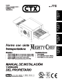
CTX Mighty Chef TCO21140077 Owner's Operating & Installation Manual
- Typ
- Owner's Operating & Installation Manual
- Dieses Handbuch eignet sich auch für
in anderen Sprachen
- English: CTX Mighty Chef TCO21140077
- français: CTX Mighty Chef TCO21140077
- español: CTX Mighty Chef TCO21140077
Verwandte Artikel
Andere Dokumente
-
Middleby Marshall PS570 series Installationsanleitung
-
-
Middleby PS220VL Bedienungsanleitung
-
Rommelsbacher OP 700 - WIENEU Bedienungsanleitung
-
Whirlpool ADN 513 Benutzerhandbuch
-
-
Whirlpool ADN 501 Benutzerhandbuch
-
Sammic ST-252 Benutzerhandbuch
-
Prince Castle TX-230ECE Bedienungsanleitung