Murray 621403x61NB Instruction book
- Kategorie
- Schneewerfer
- Typ
- Instruction book

Instruction Book − Snowthrower Model 621403x61NB
Betriebsanleitung − Schneefräse Modell 621403x61NB
Navodila za uporabo − SneĤna freza Model 621403x61NB
D
GB
1740265
SK

2
1740265
2
3
5
8
12
9
4
14
1
22

3
1740265
2
1
1
2
3
x
1
4
1
x
5
1
2

4
1740265
1
2
2
6
1
7
5
2
1
7
8
9
1
1
1
1
1
2
2
2
2
2
4
3
10
2
3
1
44
5
11
3
4

5
1740265
1
2
12
13
1
2
3
4
4
1
3
14
2
4
5
6
15
1
16
1
7
9
8
17

6
1740265
1
7
6
18
3
4
4
5
2
2
2
2
8
9
9
10
10
11
19
11
6
20
1
2

GB
7
1740265
CONTENTS
HAZARD SYMBOLS AND THE MEANINGS 8. . . . . . . . . .
OPERATING SYMBOLS AND THEIR MEANINGS 8. . . . .
RULES FOR SAFE OPERATION 9. . . . . . . . . . . . . . . . . . . .
ASSEMBLY 11. . . . . . . . . . . . . . . . . . . . . . . . . . . . . . . . . . . . . .
OPERATION 11. . . . . . . . . . . . . . . . . . . . . . . . . . . . . . . . . . . . .
MAINTENANCE 13. . . . . . . . . . . . . . . . . . . . . . . . . . . . . . . . . .
MAINTENANCE CHART 13. . . . . . . . . . . . . . . . . . . . . . . . . . .
TROUBLE SHOOTING CHART 15. . . . . . . . . . . . . . . . . . . . .
LIMITED WARRANTY 16. . . . . . . . . . . . . . . . . . . . . . . . . . . . .
General Information
This instruction book is written for a person with some mechanical ability.
Like most service books, not all the steps are described. Steps on how to
loosen or tighten fasteners are steps anyone can follow with some
mechanical ability. Read and follow these instructions before you use the
unit.
Know your product: If you understand the unit and how the unit
operates, you will get the best performance. As you read this manual,
compare the illustrations to the unit. Learn the location and the function of
the controls. To help prevent an accident, follow the operating instructions
and the safety rules. Keep this manual for future reference.
IMPORTANT: Many units are not assembled and are sold in cartons. It is
the responsibility of the owner to make sure the assembly instructions in
this manual are exactly followed. Other units are purchased in an
assembled condition. On assembled units, it is the responsibility of the
owner to make sure the unit is correctly assembled. The owner must
carefully check the unit according to the instructions in this manual before
it is first used.
Controls & Equipment Features (see Figure 1)
Crank Assembly (2) − Changes the direction of the discharge chute.
Chute Deflector (3) − Changes the distance the snow is thrown.
Discharge Chute (4) − Changes the direction the snow is thrown.
Auger Drive Lever (5) − Starts and stops the auger (snow gathering and
throwing) which also propels the snowthrower..
Engine Features
Stop Switch (8) − If equipped, move to the ON position to start the
engine.
Primer Button (9) − Injects fuel directly into the carburetor for fast starts
in cold weather.
Recoil Starter Handle (12) − Use to manually start the engine.
Choke Control (14) − Use to start a cold engine.
MODEL NO.: 621403x61NB
SERIAL NO.:
3500 min-1
30 kg
SKU No.:
Assembled in Suzhou, China 215218
by Limac for Briggs & Stratton Corporation
YYYY MM DD:
www.briggsandstratton.com
Declared vibration emission values in accordance with Directive 98/37/EC.
Vibration Emission according to EN 1033;1996: 7,1 m/s
2
.
Values determined at the handle when the machine was operated stationary on a
concrete surface at 3500 min−1.
Declared airborne noise emissions of LwA 104 dB is in accordance with Directive
2000/14/EC, Annex V.
Sound Pressure Level at operator position 84 dB.
Values determined at ear according to the specifications of EN ISO 11201.
Declared airborne sound
power level of 104 dB(A) is in
accordance with Directive
2000/14/EC.

GB
8
1740265
This manual contains safety information to make you
aware of the hazards and risks associated with snow
throwers, and how to avoid them. The snow thrower is designed and
intended for removal of snow, and should not be used for any other
purpose. It is important that you read and understand these
instructions, and anyone operating the equipment read and understand
these instructions.
The engine exhaust from this product contains chemicals known to the
State of California to cause cancer, birth defects, or other reproductive
harm.
WARNING
A signal word (DANGER, WARNING, or CAUTION) is used with the alert
symbol to indicate the likelihood and the potential severity of injury. In
addition, a hazard symbol may be used to represent the type of hazard.
DANGER indicates a hazard which, if not avoided, will result in
death or serious injury.
WARNING indicates a hazard which, if not avoided, could result
in death or serious injury.
CAUTION indicates a hazard which, if not avoided, might result
in minor or moderate injury.
CAUTION, when used without the alert symbol, indicates a
situation that could result in damage to the equipment.
Hazard Symbols and the meanings
These symbols are used on your equipment and defined in your operating
manual. Review and understand the meanings. The use of one of these
symbols combined with a signal word will alert you to potential hazards
and how to avoid them.
Explosion
Toxic fumes
Shock
Hot Surface
Fire
Operator’s Manual − Read and understand before
performing any activity or running equipment.
Safety Alert − Identifies safety information about
hazards that can result in personal injury.
Rotating auger
Rotating impeller
Rotating gears
Thrown objects
Keep a safe distance
from the equipment.
Shut off engine and remove spark plug connector
before performing maintenance or repair work.
Never reach into
rotating parts.
Recommended ear
protection for extended
use.
Operating Symbols and their meanings
These symbols are used on your equipment and defined in your operating
manual. It is important that you review and understand the meanings.
Failure to understand the symbols might result in harm to you.
Stop
Fuel
Choke off
Oil
Choke on
Slow
Fast
On Off
Ignition Key
Ignition Off
Ignition On
Primer bulb
Throttle
Drive Clutch
Auger Clutch
Engage
RIGHT
Auger Collector
Traction
Discharge Chute
LEFT UP
DOWN
Foward
Neutral
Reverse
Push to engage
electric start
Electric
Start
Engine
Start
Engine Run
Engine Off
Chute Deflector
Engage
Disengage
Heated Grips
Engage

GB
9
1740265
WARNING: This machine is capable ofto amputating hands and feet and throwing objects. Read these safety rules
and follow them closely. Failure to obey these rules could result in loss of control of unit, severe personal injury or
death to you, or bystanders, or damage to property or equipment. The triangle in text signifies important cau-
tions or warnings which must be followed.
Safe Operation Practices for Snowthrowers
IMPORTANT: Safety standards require operator presence controls to
minimize the risk of injury. Your snowthrower is equipped with such con-
trols. Do not attempt to defeat the function of the operator presence con-
trol under any circumstances.
Training
1. Read, understand, and follow all instructions on the machine and in the
manuals before operating this unit. Be thoroughly familiar with the con-
trols and the proper use of the equipment. Know how to stop the unit
and disengage the controls quickly.
2. Never allow children to operate the equipment. Never allow adults to
operate the equipment without proper instruction.
3. Keep the area of operation clear of all persons, particularly small
children and pets.
4. Exercise caution to avoid slipping or falling especially when operating in
reverse.
Preparation
1. Thoroughly inspect the area where the equipment is to be used and
remove all doormats, sleds, boards, wires, and other foreign objects.
2. Disengage all clutches and shift into neutral before starting the engine
(motor).
3. Do not operate the equipment without wearing adequate winter outer
garments. Wear footwear that will improve footing on slippery surfaces.
Avoid loose fitting clothing that can get caught in moving parts.
4. Handle fuel with care; it is highly flammable.
a. Use an approved fuel container.
b. Never add fuel to a running engine or hot engine.
c. Fill fuel tank outdoors with extreme care. Never fill fuel tank indoors.
Replace fuel cap securely and wipe up spilled fuel.
d. Never fill containers inside a vehicle or on a truck or trailer bed with
a plastic liner. Always place containers on the ground, away from
your vehicle, before filling.
e. When practical, remove gas−powered equipment from the truck or
trailer and refuel it on the ground. If this is not possible, then refuel
such on a trailer with a portable container, rather than from a gaso-
line dispenser nozzle.
f. Keep nozzle in contact with the rim of the fuel tank or container
opening at all times, until refueling is complete. Do not use a nozzle
lock−open device.
g. Replace gasoline cap securely and wipe up spilled fuel.
h. If fuel is spilled on clothing, change clothing immediately.
5. Use extension cords and receptacles as specified by the manufactur-
er for all units with electric drive motors or electric starting motors.
6. Adjust the collector housing height to clear gravel or crushed rock
surfaces.
7. Never attempt to make any adjustments while the engine (motor) is
running (except when specifically recommended by manufacturer).
8. Let engine (motor) and snowthrower adjust to outdoor temperatures
before starting to clear snow.
9. Always wear safety glasses or eye shields during operation or while
performing an adjustment or repair to protect eyes from foreign objects
that may be thrown from the machine.
Operation
1. Do not put hands or feet near or under rotating parts. Keep clear of the
discharge opening at all times.
2. Exercise extreme caution when operating on or crossing gravel drives,
walks or roads. Stay alert for hidden hazards or traffic.
3. After striking a foreign object, stop the engine (motor), remove the wire
from the spark plug, disconnect the cord on electric motors, thoroughly
inspect snowthrower for any damage, and repair the damage before
restarting and operating the snowthrower.
4. If the unit should start to vibrate abnormally, stop the engine (motor)
and check immediately for the cause. Vibration is generally a warning
of trouble.
5. Stop the engine (motor) whenever you leave the operating position,
before unclogging the collector/impeller housing or discharge chute and
when making any repairs, adjustments, or inspections.
6. When cleaning, repairing, or inspecting, make certain the collector/im-
peller and all moving parts have stopped. Disconnect the spark plug
wire and keep the wire away from the spark plug to prevent accidental
starting.
7. Do not run the engine indoors, except when starting the engine and for
transporting the snowthrower in or out of the building. Open the outside
doors; exhaust fumes are dangerous (containing CARBON MONOX-
IDE, an ODORLESS and DEADLY GAS).
8. Exercise extreme caution when operating on slopes. Do not attempt to
clear steep slopes.
9. Never operate the snowthrower without proper guards, plates, or other
safety protective devices in place and working.
10. Never direct the discharge toward people or areas where property
damage can occur. Keep children and others away.
11. Do not overload the machine capacity by attempting to clear snow at
too fast a rate.
12. Never operate the machine at high transport speeds on slippery sur-
faces. Look behind and use care when operating in reverse.
13. Disengage power to the collector/impeller when snowthrower is trans-
ported or not in use.
14. Use only attachments and accessories approved by the manufacturer
of the snowthrower (such as cabs, tire chains, etc..).
15. Never operate the snowthrower without good visibility or light. Always
be sure of your footing and keep a firm hold on the handles. Walk,
never run.
16. Never touch a hot engine or muffler.
17. Never operate the snowthrower near glass enclosures, automobiles,
window wells, drop−offs, and the like without proper adjustment of the
snow discharge angle.
18. Never direct discharge at bystanders or allow anyone in front of the
unit.
19. Never leave a running unit unattended. Always disengage the auger
and traction controls, stop engine, and remove keys.
20. Do not operate the unit while under the influence of alcohol or drugs.
21. Keep in mind the operator is responsible for accidents occurring to
other people or property.
22. Data indicates that operators, age 60 years and above, are involved
in a large percentage of power equipment−related injuries. These
operators should evaluate their ability to operate the unit safely
enough to protect themselves and others from injury.
23. DO NOT wear long scarves or loose clothing that could become
entangled in moving parts.
24. Snow can hide obstacles. Make sure to remove all obstacles from
the area to be cleared.

GB
10
1740265
Children
Tragic accidents can occur if the operator is not alert to the presence of chil-
dren. Children are often attracted to the unit and the operating activity. Never
assume that children will remain where you last saw them.
1. Keep children out of the area and under the watchful care of another
responsible adult.
2. Be alert and turn off if children enter the area.
3. Never allow children to operate the unit.
4. Use extra care when approaching blind corners, shrubs, trees, or
other objects that may obscure vision.
Clearing A Clogged Discharge Chute
Hand contact with the rotating impeller inside the discharge chute is the
most common cause of injury associated with snowthrowers. Never use
your hand to clean out the discharge chute.
To clear the chute:
1. SHUT OFF THE ENGINE.
2. Wait 10 seconds to be sure the impeller blades have stopped rotating.
3. Always use a clean out tool, not your hands.
Service, Maintenance And Storage
1. Check shear bolts and other bolts at frequent intervals for proper tight-
ness to be sure the equipment is in safe working condition.
2. Never store the machine with fuel in the tank inside a building where
ignition sources are present such as hot water and space heaters, or
clothes dryers. Allow the engine to cool before storing in any enclosure.
3. Always refer to operator’s manual for important details if the snow-
thrower is to be stored for an extended period.
4. Maintain or replace safety and instruction labels as necessary.
5. Run the machine a few minutes after throwing snow to prevent freeze−
up of the collector/impeller.
6. If fuel is spilled, do not attempt to start the engine but move the ma-
chine away from the area of spillage and avoid creating any source of
ignition until fuel vapors have dissipated.
7. Always observe safe refueling and fuel handling practices when re-
fueling the unit after transportation or storage.
8. Always follow the engine’s manual instructions for storage preparations
before storing the unit for both short and long term periods,
9. Always follow the engine manual instructions for proper start-up pro-
cedures when returning the unit to service.
10. Maintain or replace safety and instruction labels as necessary.
11. Keep nuts and bolts tight and keep equipment in good condition.
12. Never tamper with safety devices. Check their proper operation regular-
ly and make necessary repairs if they are not functioning properly.
13. Components are subject to wear, damage, and deterioration. Frequent-
ly check components and replace with manufacturer’s recommended
parts, when necessary.
14. Check control operation frequently. Adjust and service as required.
15. Use only factory authorized replacement parts when making repairs.
16. Always comply with factory specifications on all settings and adjust-
ments.
17. Only authorized service locations should be utilized for major service
and repair requirements.
18. Never attempt to make major repairs on this unit unless you have been
properly trained. Improper service procedures can result in hazardous
operation, equipment damage and voiding of manufacturer’s warranty.
19. Check shear bolts (pins) and other bolts at frequent intervals for proper
tightness to be sure the equipment is in safe working condition.
Emissions
1. Engine exhaust from this product contains chemicals known, in certain
quantities, to cause cancer, birth defects, or reproductive harm.
2. If available, look for the relevant Emissions Durability Period and Air
Index information on the engine emissions label.
Ignition System
1. This spark ignition system complies with Canadian ICES-002.

GB
11
1740265
ASSEMBLY
Read and follow the assembly and adjustment
instructions for your snow thrower. All fasteners
are in the parts bag. Do not discard any parts or
material until the unit is assembled.
WARNING: Before doing any as-
sembly or maintenance to the snow
thrower, remove the wire from the
spark plug.
NOTE: In this instruction book, left and right
describe the location of a part from the oper-
ator’s position behind the unit.
NOTE: Torque is measured in foot pounds
(metric N.m). This measurement describes
how tight a nut or bolt must be. The torque is
measured with a torque wrench.
NOTE: Illustrations are located on page 2
and on pages 3 through 6.
Tools Required
1Knife
1 Pliers
How To Remove The Snow Thrower
From The Carton
1. Locate and remove the container of oil.
2. Locate all parts that are packed separately
and remove from the carton.
3. Remove and discard the packing material
from around the snow thrower.
4. Cut down all four corners of the carton and
lay the side panels flat.
5. Hold onto the lower handle and pull the snow
thrower off the carton.
CAUTION: DO NOT back over cables.
6. Remove the packing material from handle
assembly. Remove the lower insert from the
axle.
How To Assemble The Handle
1. Remove the packing material from the upper
and lower handles.
2. (Figure 2) Loosen the knobs (1) on each
side of the handle (2).
3. Raise the upper handle (2) to the operating
position. Hold the upper handle (2) apart to
prevent scratching the lower handle.
NOTE: Make sure the auger drive cable is
not caught between the upper and lower
handle.
4. Tighten the knobs (1).
How To Prepare The Engine
WARNING: Follow the engine
manufacturer’s instructions for the
type of fuel and oil to use. Always
use a safety fuel container. Do not smoke
when adding fuel to the fuel tank. When
inside an enclosure, do not fill the fuel
tank. Before you add the fuel, stop the en-
gine. Let the engine cool for several min-
utes.
See the engine manufacturer’s instructions for
the type of fuel and oil to use. Before you use
the unit, read the information on safety, opera-
tion, maintenance, and storage.
NOTE: Engine horsepower ratings may vary
by engine adjustments, manufacturing vari-
ances, altitude, atmospheric conditions, fuel
and maintenance.
Add Oil To The Engine (Figure 3)
NOTE: Engine may already contain some
residual oil. Check frequently when filling
the crankcase. DO NOT overfill.
The snow thrower was shipped with a container
of 5W30 motor oil. This oil must be added to the
engine before operating.
1. Make sure the unit is level.
2. Remove the oil fill cap/dipstick (1) and fill
the crankcase to “FULL” line on dipstick. DO
NOT overfill.
3. Tighten the oil fill cap/dipstick (1) securely
each time you check the oil level.
NOTE: Synthetic oil can assist with starting
in extreme cold temperatures. Synthetic
5W30 is acceptable for all temperatures. DO
NOT mix oil with petrol.
Add Petrol To The Engine
This engine is certified to operate on petrol. Ex-
haust Emission Control System: EM (Engine
Modifications).
WARNING: Alcohol blended fuels
(called gasohol or those using
ethanol or methanol) can attract
moisture which leads to separation and
formation of acids during storage. Acidic
gas can damage the fuel system of an en-
gine while in storage.
NOTE: To avoid engine problems, the fuel
system must be emptied before storage for
30 days or longer. Start the engine and let it
run until the fuel lines and carburetor are
empty. Use fresh fuel next season. See the
Storage section in this manual for additional
information.
Fill the fuel tank only with a fresh, clean, un-
leaded regular, unleaded premium, or reformu-
lated automotive petrol with a minimum of 85
octane. DO NOT use leaded petrol. Make sure
that the container you pour the petrol from is
clean and free from rust or other foreign par-
ticles. Never use petrol that may be stale from
long periods of storage in the container.
Before You Operate
Before you operate your new snow thrower,
please review the following checklist:
G Make sure all assembly instructions have
been completed.
G Make sure the discharge chute rotates freely.
G Make sure that no loose parts remain in the
carton.
As you learn how to properly use the snow
thrower, pay extra attention to the following im-
portant items.
G Make sure the engine oil is at the proper
level. For the type engine oil to use, see the
Engine Manufacturer’s manual.
G Make sure gas tank is filled properly with
clean, fresh, unleaded petrol with a minimum
of 85 octane.
G Become familiar with the location of all
controls and understand their function.
G Before starting the engine, make sure all
controls operate correctly.
OPERATION
NOTE: Illustrations are located on page 2
and on pages 3 through 6.
CAUTION: Use only attachments and acces-
sories approved by the manufacturer of the
snow thrower (such as tire chains, electric
start kits, etc.).
Know Your Snow Thrower (Figure 1)
Read this Instruction Book and safety rules be-
fore operation the snow thrower. Compare the
illustration with your snow thrower to familiarize
yourself with the location of various controls and
adjustments.
How To Control
The Discharge Of The Snow
WARNING: Never direct the dis-
charge of snow toward bystanders.
WARNING: Always stop the engine
before unclogging the discharge
chute or the auger housing and be-
fore leaving the snow thrower.
1. (Figure 1) Turn the crank assembly (2) to
change the discharge direction of the snow.
2. (Figure 6) Loosen the wing knob (1) on the
chute deflector (2).
3. Move the chute deflector (2) up for more
distance or down for less distance.
4. Tighten the wing knob (1).
How To Throw Snow (Figure 1)
1. Engage the auger drive lever (5).
2. To stop throwing snow, release the auger
drive lever (5).
WARNING: The operation of any
snow thrower can result in foreign
objects being thrown into the eyes,
which can result in severe eye damage.
Always wear safety glasses or eye shields
while operating the snow thrower. We rec-
ommend standard safety glasses or use a
wide vision safety mask over your glasses.
How To Stop Discharging Snow
(Figure 1)
1. To stop discharging snow, release the auger
drive lever (5).
NOTE: If the snow thrower continues to
slowly move forward, see “How To Adjust
The Auger Control Cable” in the Mainte-
nance Section.
2. To stop the engine, push the stop switch (8)
to the off position.
CAUTION: To stop the engine, do not move
the choke control to CHOKE position. Back-
fire or engine damage can occur.

GB
12
1740265
2. To go forward, raise the handle (2) to allow
the rubber auger blades to contact the
ground. Maintain a firm hold on the handle
(2) as the snow thrower starts to move for-
ward. Guide the snow thrower by moving the
handle (2) either left or right. Do not attempt
to push the snow thrower.
3. To stop, release the auger drive lever (5).
NOTE: If the auger continues to rotate, see
“How To Adjust The Auger Control Cable” in
the Maintenance section.
Before Starting The Engine
1. Before you service or start the engine, famil-
iarize yourself with the snow thrower. Be
sure you understand the function and loca-
tion of all controls.
2. Make sure that all fasteners are tight.
3. Make sure the fuel tank is filled with the cor-
rect mixture of gasoline and oil.
4. Become familiar with the location of all con-
trols and understand their function.
5. Before starting the engine, make sure all
controls operate corrently.
How To Stop The Engine (Figure 1)
To stop the engine, push the stop switch (8) to
the off position.
CAUTION: To stop the engine, do not move
the choke control to CHOKE position. Back-
fire or engine damage can occur.
How To Start The Engine (Figure 1)
Make sure that the engine oil is at FULL mark on
dipstick. The engine is equipped with a recoil
starter. Before starting the engine, make certain
that you have read the following information.
If engine floods, set the choke to the OPEN/
RUN position and crank until the engine starts.
WARNING: Rapid retraction of the
starter cord (kickback) will pull
your hand or arm toward the en-
gine faster than you can let go of the start-
er cord.
S When starting the engine, slowly pull
the starter cord until resistance is felt.
Then, rapidly pull the starter cord.
S Make sure components; such as impel-
lors, pulleys or sprockets, are securely
attached.
How To Start A Cold Engine (Figure 1)
1. (Figure 1) Push the stop switch (8) to the
ON position.
2. When starting the engine, do not engage the
auger drive lever.
3. Move the choke control (14) to the FULL
choke position.
4. Push the primer button (9) as specified be-
low. Remove finger from the primer button
(9) between primes.
S Push two times if temperature is 15° F
(−9° C) or higher.
S Push four times if temperature is below
15° F (−9° C).
5. (Figure 4) Slowly pull the recoil starter han-
dle (1) until resistance is felt and then pull
rapidly to start the engine. Do not allow the
recoil starter handle (1) to snap back. Slow-
ly return the recoil starter handle (1).
NOTE: In temperatures below 0F, allow
the engine to warm up for several minutes
before blowing snow.
WARNING: Never run the engine
indoors or in enclosed, poorly ven-
tilated areas. Engine exhaust con-
tains carbon monoxide, an odorless and
deadly gas. Keep hands, feet, hair and
loose clothing away from any moving parts
located on the engine or the snow thrower.
The temperature of muffler and nearby
areas may exceed 150°F. Avoid these
areas.
How To Start A Warm Engine (Figure 1)
If an engine has been running and is still warm,
leave the choke control (14) in the off position
and do not push the primer button (9). If the
engine fails to start, follow the instructions “How
To Start A Cold Engine”.
NOTE: Do not use the primer button (9) to
start a warm engine.
How To Start An Engine With A Frozen Electric
Starter (Figure 1)
If the starter is frozen and will not turn the en-
gine, follow the instructions below.
1. Pull out the recoil starter handle (12) as far
as possible.
2. Quickly release the recoil starter handle
(12). Allow the recoil starter handle (12) to
snap back against the recoil starter.
If the engine still fails to start, repeat the two pre-
vious steps until the engine starts. Then, contin-
ue with the directions “How To Start A Cold
Engine”.
To help prevent the possible freeze−up of the
recoil starter and of the engine controls, proceed
as follows after each snow removal job.
1. Before storing, run the snow thrower a few
minutes to prevent freeze−up of the auger/
impeller.
2. With engine off, allow engine to cool for sev-
eral minutes.
3. Pull starter rope very slowly until resistance
is felt, then stop. Allow the starter rope to re-
coil. Repeat three times.
4. With the engine not running, wipe all snow
and moisture from the carburetor cover in
area of controls and levers. Also, move the
choke control and starter handle several
times.
How To Remove Snow or Debris From
The Auger Housing
(Figure 1)
WARNING: Do not attempt to re-
move snow or debris that may be-
come lodged in auger housing
without taking the following precautions.
1. Release the auger drive lever (5).
2. To stop the engine, move the stop switch
(8) to the stop position.
3. Disconnect the spark plug wire.
4. Do not place your hands in the auger hous-
ing (22) or the discharge chute (4). Use a
pry bar to remove any snow or debris.
Snow Throwing Tips
1. This snow thrower will propel itself forward
when the handle is raised enough to cause
the auger blades to contact the ground. The
auger should stop when auger control bar is
released. If it does not stop, see “How To Ad-
just The Auger Control Cable” in the adjust-
ment section.
2. Most efficient snow throwing is accomplished
when the snow is removed immediately after
if falls.
CAUTION: Do not overload the machine ca-
pacity by attempting to clear snow at too fast
a rate.
3. For complete snow removal, slightly overlap
each previous path.
4. Whenever possible, discharge the snow
down wind.
5. The distance the snow will be discharged
can be adjusted by moving the discharge
chute deflector. Raise the deflector for more
distance or lower the deflector for less dis-
tance.
6. In windy conditions, lower the chute deflector
to direct the discharged snow close to the
ground where it is less likely to blow into un-
wanted areas.
7. For safety and to prevent damage to the
snow thrower, keep the area to be cleared
free of stones, toys and other foreign objects.
8. Do not use the auger propelling feature when
clearing gravel or crushed rock driveways.
Move the handle down to slightly raise the
auger.
9. The forward speed of the snow thrower is
dependent on the depth and weight of the
snow. Experience will establish the most ef-
fective method of using the snow thrower un-
der different conditions.
10.After each snow throwing job, allow the en-
gine to run for a few minutes. The snow and
accumulated ice will melt off the engine.
11. Clean the snow thrower after each use.
12.Remove ice, snow and debris from the entire
snow thrower. Flush with water to remove all
salt or other chemicals. Wipe snow thrower
dry.
Dry And Average Snow
1. Snow up to eight inches deep can be re-
moved rapidly and easily by walking at a
moderate rate. For snow or drifts of a greater
depth,slow your pace to allow the discharge
chute to dispose of the snow as rapidly as
the auger receives the snow.
2. Plan to have the snow discharged in the di-
rection the wind is blowing.
Wet Packed Snow
Move slowly into wet, packed snow. If the wet,
packed snow causes the auger to slow down or
the discharge chute begins to clog, back off and
begin a series of short back and forth jabs into
the snow. These short back and forth jabs, four
to six inches, will “belch” the snow from the
chute.
Snow Banks And Drifts
In snow of greater depth than the unit, use the
same “jabbing” technique described above. Turn
the discharge chute away from the snow bank.
More time will be required to remove snow of
this type than level snow.

GB
13
1740265
MAINTENANCE CHART
CUSTOMER RESPONSIBILITIES
SERVICE RECORDS
Fill in dates as you
complete regular
service.
Before
Each
Use
First
2
Hours
Every
5
Hours
Every
10
Hours
Every
25
Hours
Each
Season
Before
Storage
SERVICE DATES
Check And Tighten All Screws and Nuts
√ √
Check Spark Plug
√ √
Check Drive Belt
√
Check Fuel
√
Drain Fuel
√
Lubricate Chute Control Flange
√
Check Adjustment of Auger Control Cable
√
Auger Drive Belt
√
MAINTENANCE
NOTE: Illustrations are located on page 2
and on pages 3 through 6.
Use the following maintenance section to keep
your unit in good operating condition. All the
maintenance information for the engine is in the
engine manufacturer’s instructions. Before you
start the engine, read this book.
WARNING: Before you make an in-
spection, adjustment (except
carburettor), or repair, disconnect
the wire from the spark plug.
General Recommendations
The warranty on this snow thrower does not cov-
er items that have been subjected to operator
abuse or negligence. To receive full value from
the warranty, the operator must maintain the
snow thrower as instructed in this manual.
Some adjustments must be made periodically to
properly maintain the snow thrower.
After Each Use
G Check for any loose or damaged parts.
G Tighten any loose fasteners.
G Check and maintain the auger.
G Check controls to make sure they are
functioning properly.
G If any parts are worn or damaged, replace
immediately.
G Check all safety and instruction decals and
labels. Replace any decals or labels that are
missing or cannot be clearly read.
All adjustments in the Maintenance section of
this manual should be checked at least once
each season.
How To Remove The Top Cover
(Figure 8)
1. Remove the five screws (1) from the top
cover (2).
2. Remove the top cover (2).
3. To install the top cover (4), reverse the
above steps.
Lubrication
Before Storage (Figure 8)
1. Lubricate the clute control flange (7). Apply
a clinging type of grease such as Lubriplate.
How To Adjust The Auger Control Cable
The auger control cable is adjusted at the facto-
ry. During normal use, the auger control cable
can become stretched and the auger drive lever
will not properly engage or disengage the auger.
1. (Figure 12) Loosen the nut (1) that holds the
cable tension spring (2).
2. Slide the cable tension spring (2) toward
the rear of the unit until all cable slack is re-
moved.
NOTE: The auger control cable is properly
adjusted when the free cable slack is re-
moved and there is no tension on the
idler arm.
3. Tighten the nut (1) that holds the cable ten-
sion spring (2).
If belt stretch has occured, move the end the
auger control cable to the outside hole as fol-
lows:
1. (Figure 12) Loosen the nut (1) that holds the
cable tension spring (2).
2. Move the cable tension spring (2) toward
the front of the unit to achieve maximum
cable slack.
3. (Figure 11) Remove the upper end of the
auger control cable (3) from the auger
drive lever (4).
4. Install the auger control cable (3) in the
hole shown in Figure 11.
5. (Figure 12) Slide the cable tension spring
(2) toward the rear of the unit until all cable
slack is removed.
NOTE: The auger control cable (3) is
properly adjusted when the free cable
slack is removed and there is no tension
on the idler arm.
6. Tighten the nut (1) that holds the cable ten-
sion spring (2).
7. To check the adjustment, start the snow
thrower. Make sure the auger does not rotate
when the auger drive lever is released.
How To Remove The Top Cover
(Figure 10)
There are no adjustments under the top cover
(1). To clean the engine cooling system, follow
the steps below to remove the top cover (1).
1. Remove screws (2) that attach the rod sup-
port clamp the the top cover (1). Pivot the
crank assembly rod (3) up and lay on unit.
2. Remove screws (4).
3. Remove attachment screws (5).
4. Remove the top cover (1).
5. To install the top cover (1), reverse the
above steps.
How To Remove The Belt Cover
(Figure 9)
1. Remove the screws (1) and nuts (2) from
the belt cover (3).
2. Remove attachment screw (4) from the rear
of the belt cover (3).
3. Remove the belt cover (3) from the unit.
4. To install the belt cover (3), reverse the
above steps.
NOTE: The belt cover (3) has belt guides
moulded onto the inside of the belt cover (3).
When you install the belt cover (3), engage
the auger drive lever to tighten the belt
against the pulley. This will provide adequate
clearance for the belt guides when installing
the belt cover (3).
How To Replace The Auger Drive Belt
The drive belt is of special construction and
must be replaced with an original factory re-
placement belt available from your nearest au-
thorized service center.
If the auger drive belt is damaged, the snow-
thrower will not discharge snow and will not
move forward. Replace the damaged belt as
follows:
1. Disconnect the spark plug wire.

GB
14
1740265
2. Remove the belt cover. See “How To Re-
move The Belt Cover”.
3. Note the path of the auger drive belt (1). For
assistance, a diagram decal is provided.
4. (Figure 14) Remove the belt guide screw
(2) and the belt guide (3). To remove the
belt guide (3), rotate the belt guide (3)
down.
5. (Figure 15) Remove the idler screw (4) and
idler pulley (5) from the idler arm (6).
6. (Figure 16) Remove the auger drive belt (1)
from the engine pulley and pull through side
of motor box.
7. (Figure 17) To remove the auger drive belt
(1) from the impeller pulley (7), move the
idler arm to the engaged position. This will
provide clearance (8) between the impeller
pulley (7) and the brake arm (9) to remove
the auger drive belt.
8. To install a new auger drive belt (1), reverse
the above steps.
9. Check the adjustment of the auger drive
cable. See “Adjust Auger Control Cable”.
How To Remove The Auger
1. Remove the belt cover. See “How To Re-
move The Belt Cover”.
2. Remove the auger drive belt. See “How To
Replace The Auger Drive Belt”.
3. (Figure 18) Remove the auger pulley (1)
from the auger shaft (threads are left hand;
turn clockwise to remove).
4. To keep the auger (6) from rotating, set a
2”x4” piece of wood on the center paddle
(3) to secure auger (6).
5. Remove bolts (4), washer (5), and nuts (2)
from front of right cover (7).
6. Remove screw (8) from back of right cover
(7).
7. Remove bolts (9) and nuts (10).
8. (Figure 19) Slide the auger (6) out of the
right side of the auger housing (11).
9. Slide the auger (6) out of the bearing on the
left side of the auger housing (11).
10.To install auger (6), reverse the above steps.
Lubrication
How To Check The Engine Oil (Figure 3)
Check the oil level before starting the engine
and after each eight (8) hours of continuous use.
1. Make sure the unit is level.
2. Remove the oil fill cap/dipstick (1) and fill
the crankcase to “FULL” line on dipstick. DO
NOT overfill.
3. Tighten the oil fill cap/dipstick (1) securely
each time you check the oil level.
NOTE: Synthetic oil can assist with starting
in extreme cold temperatures. Synthetic
5W30 is acceptable for all temperatures. DO
NOT mix oil with petrol.
How To Change The Engine Oil
Change the engine oil every fifty (50) hours or at
least once a year if the snow thrower is not used
for fifty (50) hours.
To change the engine oil, the engine must be
tilted forward and the oil drained from the oil fill
tube. Change oil when the engine is warm.
1. (Figure 5) Lift the rear of the snowthrower
and tilt the unit forward. In the correct posi-
tion, the snowthrower will be setting on the
front of the auger housing.
2. Put an oil drain pan (1) under the oil fill
tube (2).
3. Carefully remove the oil fill cap/dipstick. Oil
will begin to flow into the oil drain pan (2).
4. After all the oil has drained from the engine,
set the snowthrower in the upright operating
position.
5. (Figure 3) Fill the engine with S.A.E. 5W30
oil. Make sure the oil reaches the FULL mark
on the oil fill cap/dipstick. DO NOT OVER-
FILL.
NOTE: Synthetic oil can assist with starting
in extreme cold temperatures. Synthetic
5W30 is acceptable for all temperatures. DO
NOT mix oil with petrol.
How To Replace The Spark Plug
(Figure 20)
NOTE: This spark ignition system meets all
requirements of the Canadian Interference−
Causing Equipment Regulations.
NOTE: This engine complies with all current
Australian and New Zealand limitations elec-
tromagnetic interference.
Check the spark plug (1) every twenty-five (25)
hours. Replace the spark plug (1) if the elec-
trodes are pitted or burned, if the porcelain is
cracked, or every 100 hours of use.
1. Make sure the spark plug (1) is clean. Clean
the spark plug (1) by carefully scraping the
electrodes (do not sand blast or use a wire
brush).
2. Check the spark plug (1) gap with a feeler
gauge (2) and reset gap to 0.030” if neces-
sary..
3. Before installing the spark plug (1), coat the
threads lightly with oil for easy removal.
Tighten the spark plug (1) to a torque of 15
foot-pounds.
How To Prepare The Snow Thrower For
Storage
WARNING: Do not remove petrol
while inside a building, near a fire,
or while you smoke. Petrol fumes
can cause an explosion or a fire.
If the snow thrower is to be stored for an ex-
tended period, refer to the engine manufactur-
er’s operating manual (included with some
models) for important maintenance or storage
details.
1. Drain the fuel tank.
2. Let the engine run until it is out of gasoline.
3. Never store the snow thrower with fuel in the
tank inside a building where ignition sources
are present such as hot water and space
heaters, clothes dryers, and the like. Allow
the engine (motor) to cool before storing in
any enclosure.
4. Drain the oil from the warm engine. Fill the
engine crankcase with new oil.
5. Remove the spark plug from the cylinder.
Pour one ounce of oil into the cylinder. Slow-
ly pull the recoil−start grip so that the oil will
protect the cylinder. Install a new spark plug
in the cylinder.
6. Thoroughly clean the snow thrower.
7. Lubricate all lubrication points. See the Main-
tenance section.
8. Be sure that all nuts, bolts and screws are
securely fastened. Inspect all visible moving
parts for damage, breakage and wear. Re-
place if necessary.
9. Cover the bare metal parts of the blower
housing and auger with spray rust preventa-
tive lubricant.
10.Put the unit in a building that has good ven-
tilation.
11. If the machine must be stored outdoors,
block up the snow thrower to be sure the en-
tire machine is off the ground.
12.Cover the snow thrower with a suitable pro-
tective cover that does not retain moisture.
Do not use plastic.
How To Order Replacement Parts
The replacement parts are shown either on the
back pages of this Instruction Book or in a
separate Parts List Book.
Use only manufacturer’s authorized or approved
replacement parts. The letter placed on the end
of the part number denotes the type of finish for
the part, C for chrome, Z for zinc, a PA for
purchased assembly. It is important that you
include this when ordering a part. Do not use
attachments or accessories not specifically
recommended for this unit. In order to obtain
proper replacement parts you must supply the
model number (see nameplate).
Replacement parts, except for the engine, trans-
mission, transaxle or differential, are available
from the store where the mower was purchased
or a service shop recommended by the store.
Warranty service is available only through Autho-
rized Service Dealers. Locate your nearest dealer
in our locator map at www.murray.com.
Replacement parts for the engine, transaxle, or
transmission, are available from the
manufacturer’s authorized service center found
in the yellow pages of the telephone directory.
Also, see the individual engine or transmission
warranties to order replacement parts.
When ordering the following information is
required:
(1) The Model Number
(2) Serial Number
(3) Part Number
(4) Quantity

GB
15
1740265
TROUBLE SHOOTING CHART
TROUBLE CAUSE CORRECTION
Difficult starting Defective spark plug. Replace spark plug.
Water or dirt in fuel system. Use carburetor bowl drain to flush and refill with
fresh fuel.
Engine runs erratic Blocked fuel line, empty gas tank, or stale
gasoline
Clean fuel line; check fuel supply; add fresh
gasoline
Engine stalls Unit running on CHOKE. Set choke lever to RUN position.
Engine runs erratic;
Loss of power
Water or dirt in fuel system. Use carburetor bowl drain to flush and refill with
fresh fuel.
Excessive vibration Loose parts: damaged impeller Stop engine immediately and disconnect spark
plug wire. Tighten all bolts and make all
necessary repairs. If vibration continues, have
the unit serviced by a competent repairman.
Unit fails to propel itself Drive belt loose or damaged. Replace drive belt.
Unit fails to discharge snow Auger drive belt loose or damaged. Adjust auger drive belt; replace if damaged.
Auger control cable not adjusted correctly. Adjust auger control cable.
Discharge chute clogged. Stop engine immediately and disconnect spark
plug wire. Clean discharge chute and inside of
auger housing.
Foreign object lodged in auger Stop engine immediately and disconnect spark
plug wire. Remove object from auger.

GB
16
1740265
BRIGGS & STRATTON CORPORATION OWNER WARRANTY POLICY
Effective January 1, 2006 replaces all undated Warranties and all Warranties dated before January 1, 2006
Briggs & Stratton Corporation will repair or replace, free of charge, any part(s) of the product that is defective in material or workmanship or both.
Transportation charges on product submitted for repair or replacement under this warranty must be borne by purchaser. This warranty is effective
for the time periods and subject to the conditions stated below. For warranty service, find the nearest Authorized Service Dealer in your area. For
warranty service, find the nearest Authorized Service Dealer in our dealer locator map at www.murray.com.
THERE IS NO OTHER EXPRESS WARRANTY. IMPLIED WARRANTIES, INCLUDING THOSE OF MERCHANTABILITY AND FITNESS FOR A
PARTICULAR PURPOSE, ARE LIMITED TO ONE YEAR FROM PURCHASE, OR TO THE EXTENT PERMITTED BY LAW ANY AND ALL
IMPLIED WARRANTIES ARE EXCLUDED. LIABILITY FOR INCIDENTAL OR CONSEQUENTIAL DAMAGES ARE EXCLUDED TO THE
EXTENT EXCLUSION IS PERMITTED BY LAW. Some states or countries do not allow limitations on how long an implied warranty lasts, and
some states or countries do not allow the exclusion or limitation of incidental or consequential damages, so the above limitation and exclusion
may not apply to you. This warranty gives you specific legal rights and you may also have other rights which vary from state to state or country to
country.
LIMITED WARRANTY
WARRANTY TERMS
Consumer Commercial Condition of
Brand / Unit Use Use Warranty Term
Single Stage Snowthrower 1 year 90 days. . . . . . . . . . . . . . . . . . . . . .
Dual Stage Snowthrower 2 year 90 days. . . . . . . . . . . . . . . . . . . . . . .
The warranty period begins on the date of purchase by the first retail consumer or commercial end user, and continues for the period of
time stated in the table above. “Consumer use” means personal residential household use by a retail consumer. “Commercial use” means
all other uses, including use for commercial, income producing or rental purposes. Once product has experienced commercial use, it shall
thereafter be considered as commercial use for purposes of this warranty.
No warranty registration is necessary to obtain warranty on Murray branded products. Save your proof of purchase receipt. If you do not
provide proof of the initial purchase date at the time warranty service is requested, the manufacturing date of the product will be used to
determine the warranty.
ABOUT YOUR WARRANTY
We welcome warranty repair and apologize to you for being inconvenienced. Any Authorized Service Dealer may perform warranty
repairs. Most warranty repairs are handled routinely, but sometimes requests for warranty service may not be appropriate. For example,
warranty service would not apply to the product if damage occurred because of misuse, lack of routine maintenance, shipping, handling,
warehousing or improper installation. Similarly, the warranty is void if the serial number on the product has been removed or the product
has been altered or modified.
This warranty covers product related defective material and/or workmanship only. To avoid misunderstanding which might occur be-
tween the customer and the Dealer, listed below are some of the causes of product failure that the warranty does not cover.
• Normal Wear: Small Engine Powered Equipment, like all mechanical devices, needs periodic parts and service to perform well. Warranty does not
cover repair when normal use has exhausted the life of the product or part.
• Installation: This warranty does not apply to product that has been subjected to improper or unauthorized installation, alteration or modification. Nor
installations that prevent starting, cause unsatisfactory engine performance.
• Improper Maintenance: The life of this product depends upon the conditions under which it operates, and the care it receives. Recommended
maintenance and adjustment intervals are stated in the Operator’s Manual. Often product, such as tillers, edgers, rotary mowers, are used in dusty
or dirty conditions, which can cause what appears to be premature wear. Such wear, when caused by dirt, dust, or other abrasive material entering
the product because of improper maintenance is not covered by warranty. The warranty will not cover repairs due to problems caused by replace-
ment parts that are not original manufactured part(s).
• Incorrect and/or insufficient fuel or lubrication: This warranty does not cover damage caused by the use of stale fuel, or altered gasolines. Dam-
age to engine or engine components ie, combustion chamber, valves, valve seats, valve guides, burned starter motor windings caused by use of
alternate fuels such as liquified petroleum, natural gas, are not covered unless engine is certified for this operation. Parts which are scored or bro-
ken because product was operated with insufficient, contaminated or incorrect grade of lubricating oil as well as product components damaged due
to lack of lubrication are not covered.
• Operational Misuse: Proper operation of the product is stated in the Operator’s Manual. Product damaged by overspeeding, overheating, or opera-
tion in a confined area without sufficient ventilation. Product broken by excessive vibration caused by a loose engine mounting, loose or unbalanced
blades, impellers, overspeeding, or bent crankshaft due to striking of solid object. Damage or malfunctions resulting from accidents, abuse, or im-
proper servicing or freezing or chemical deterioration, as well as operating in excess of recommended capacities as outlined in the Operator’s
Manual are not covered.
• Routine tune-up, wear items or adjustments: This warranty excludes wear items such as oil, belts, blades, o-rings, filters, etc.
• Other exclusions: Repair or adjustments for part(s) that are not manufactured by Briggs & Stratton Corporation, are not covered, see warranty for
respective manufacturers. This warranty excludes failures due to acts of God and other force majeure events beyond the manufacturers con-
trol. Also excluded are used, reconditioned, and demonstration products.
Warranty service is available only through Authorized Service Dealers. Locate your nearest dealer in our locator map at www.murray.com.

D
17
1740265
INHALT
GEFAHRENSYMBOLE UND IHRE BEDEUTUNGEN 18. .
BETRIEBSSYMBOLE UND IHRE BEDEUTUNGEN 18. . .
REGELN FÜR DEN SICHEREN BETRIEB 19. . . . . . . . . . .
ZUSAMMENBAU 21. . . . . . . . . . . . . . . . . . . . . . . . . . . . . . . . .
BEDIENUNG 21. . . . . . . . . . . . . . . . . . . . . . . . . . . . . . . . . . . . .
WARTUNG 24. . . . . . . . . . . . . . . . . . . . . . . . . . . . . . . . . . . . . . .
WARTUNGSTABELLE 24. . . . . . . . . . . . . . . . . . . . . . . . . . . .
FEHLERSUCHE 26. . . . . . . . . . . . . . . . . . . . . . . . . . . . . . . . . .
EINGESCHRÄNKTE GEWÄHRLEISTUNG 27. . . . . . . . . . .
Allgemeines
Bei dieser Bedienungsanleitung werden einige handwerkliche
Grundkenntnisse vorausgesetzt. Wie in den meisten
Wartungshandbüchern werden nicht alle Schritte beschrieben. Das
Lösen und Anziehen von Schrauben kann jeder ohne große
handwerkliche Fähigkeiten bewältigen. Lesen und befolgen Sie diese
Anweisungen, bevor Sie das Gerät benutzen.
Informieren Sie sich über Ihr Produkt: Sie erzielen die beste Leistung,
wenn Sie das Gerät und dessen Funktionen verstehen. Beim Lesen
dieser Bedienungsanleitung vergleichen Sie die Abbildungen mit dem
Gerät. Machen Sie sich mit der Anordnung und Funktion der
Bedienelemente vertraut. Befolgen Sie die Anweisungen zum Betrieb
und die Sicherheitshinweise, um einen Unfall zu verhindern. Bewahren
Sie diese Bedienungsanleitung auf, um später darauf zurückgreifen zu
können.
WICHTIG: Viele Geräte sind nicht vollständig zusammengebaut und
werden in Kartons verpackt verkauft. Der Eigentümer muss die
Montageanweisungen in dieser Bedienungsanleitung genau befolgen.
Andere Geräte werden im vor−montierten Zustand verkauft. Bei
montierten Geräten ist der Eigentümer dafür verantwortlich zu prüfen, ob
das Gerät korrekt montiert ist. Der Eigentümer muss das Gerät vor dem
ersten Gebrauch entsprechend der Anweisungen in dieser
Bedienungsanleitung sorgfältig prüfen.
Bedienelement & Gerätefunktionen (siehe Abbildung 1)
Auswurfkurbel (2) − Ändert die Richtung des Aeuswurfkamins.
Auswurfumlenkvorrichtung (3) − Ändert den Abstand, in dem der
Schnee ausgeworfen wird.
Auswurfkamin (4) − Ändert die Richtung, in die der Schnee
ausgeworfen wird.
Räumwerkhebel (5) − Startet und hält die Frässchnecke und die
Wurfeinrichtung an (Sammeln und Auswerfen des Schnees).
Motorfunktionen
Stoppschalter (8) − Muss in die Position AN geschoben werden, um
Motor zu starten.
Initialzündungsknopf (9) − Spritzt Benzin direkt in den Vergaser ein,
damit Motor bei kaltem Wetter schnell anspringt.
Rückstarterhebel (12) − Zum manuellen Anlassen des Motors.
Choke (14) − Zum Anlassen eines kalten Motors.
MODEL NO.: 621403x61NB
SERIAL NO.:
3500 min-1
30 kg
SKU No.:
Assembled in Suzhou, China 215218
by Limac for Briggs & Stratton Corporation
YYYY MM DD:
www.briggsandstratton.com
Angegebene Vibrationsemissionswerte gemäß Richtlinie 98/37/EC.
Vibrationsemission gemäß EN 1033;1996: 7,1 m/s
2
.
Werte ermittelt am Griff während Gerät stationär auf einer Betonfläche mit 3500
min−1 betrieben wurde.
Angegebene Geräuschemissionen von LwA 104 dB erfüllen Richtlinie 2000/14/EC,
Anhang V.
Schalldruckpegel an Bedienerposition: 84 dB.
Werte am Ohr gemäß den Spezifikationen in EN ISO 11201 ermittelt.
Angegebener
Geräuschemissions−Schalld
ruckpegel von 104 dB(A)
erfüllt Richtlinie 2000/14/EC.

D
18
1740265
Dieses Handbuch beinhaltet
Sicherheitsinformationen, um Ihnen die Gefahren
und Risiken im Zusammenhang mit Schneefräsen
bewusst zu machen, und Ihnen zu vermitteln, wie man sie
vermeidet. Die Schneefräse wurde zur Räumung von Schnee
entwickelt und sollte zu keinem anderen Zweck verwendet werden.
Es ist wichtig, dass Sie sich diese Anleitung gut durchlesen und sie
verstehen, und ebenso sollte jeder, der mit dem Gerät arbeitet,
diese Anleitung lesen und verstehen.
Die Motorabgase dieses Produkts enthalten Chemikalien, von denen im
Staat Kalifornien bekannt ist, dass sie Krebs, Geburtsfehler hervorraufen
und andere negative Auswirkungen auf die Fortpflanzung haben können.
WARNUNG
Ein Signalwort (GEFAHR, WARNUNG oder VORSICHT) wird zusammen mit
dem Warnsymbol verwendet, um die Wahrscheinlichkeit und die potentielle
Schwere von Verletzungen anzuzeigen. Außerdem kann ein Gefahrensymbol
verwendet werden, um den Gefahrentyp darzustellen
GEFAHR weist auf eine Gefährdung hin, deren
Nichtbeachtungzum Tod oder zu schweren Verletzungen
führen kann.
WARNUNG weist auf eine Gefährdung hin, deren
Nichtbeachtung zum Tod oder zu schweren Verletzungen
führen könnte.
VORSICHT weist auf eine Gefährdung hin, deren
Nichtbeachtung zum Tod oder zu leichten bis mittelschweren
Verletzungen führen könnte.
Wird VORSICHT ohne das Warnsymbol verwendet, weist dies
auf eine Situation hin, die zu Schäden am Gerät führen
könnte.
Gefahrensymbole und ihre Bedeutungen
Diese Symbole werden an Ihrem Gerät verwendet und sind in Ihrer
Bedienungsanleitung definiert. Lesen Sie zu ihren Bedeutungen nach und
merken Sie sich diese. Die Verwendung dieser Symbole in Verbindung mit
einem Signalwort wird Sie auf potentielle Gefahren und deren Vermeidung
hinweisen.
Explosion
Toxische Gase
Schock
Heiße
Oberfläche
Feuer
Bedienungsanleitung – Lesen Sie diese bevor Sie
jegliche Aktivitäten durchführen oder das Gerät
betreiben.
Sicherheitswarnung – identifiziert
Sicherheitsinformationen zu Gefahren, die zu
Verletzungen an Personen führen können.
Rotierende
Schnecke
Rotierendes
Gebläserad
Rotierende
Getriebe
Hochfliegende
Objekte
Sicherheitsabstand
zum Gerät einhalten.
Schalten Die den Motor ab und entfernen Sie den
Zündkerzenstecker, bevor Sie Wartungs− oder
Reparaturarbeiten durchführen.
Nicht in rotierende
Teile greifen.
Empfohlener
Gehörschutz für die
längere Verwendung.
Betriebssymbole und ihre Bedeutungen
Diese Symbole werden an Ihrem Gerät verwendet und sind in Ihrer
Bedienungsanleitung definiert. Es ist wichtig, dass Sie die Bedeutungen lesen
und verstehen. Ein Nichtverstehen der Symbole kann zu Verletzungen führen.
Stop
Kraftstoff
Choke auf
Öl
Choke ein
Langsam
Schnell
Ein Aus
Zündschlüssel
Zündung aus
Zündung ein
Primerkopf
Gashebel
Antriebskupplung
Schneckenkupplung
Einkuppeln
RECHTS
Schneckensammler
Antrieb
Auswurfkanal
LINKS HINAUF
HERUNTER
Vorwärts
Neutral
Rückwärts
Drücken, um den
elektrischen Start
einzukuppeln
Elektrischer
Start
Motorstart
Betrieb des
Motors
Motor aus
Kanalleitblech
Einkuppeln
Auskuppeln
Beheizte Griffe
Einkuppeln

D
19
1740265
WARNUNG: Diese Maschine kann Hände und Füße abschneiden und Objekte schleudern. Lesen Sie sich
diese Regeln durch und befolgen Sie sie strikt. Eine Nichteinhaltung dieser Regeln kann dazu führen, dass
Sie die Kontrolle über das Gerät verlieren, was zu schweren Verletzungen an Ihrer Person und anderen
Personen oder zum Tod führen kann und Sachschäden verursachen kann. Das Dreieck im Text stellt
wichtige Warnungen dar, die unbedingt befolgt werden müssen.
REGELN FÜR DEN SICHEREN BETRIEB
Sichere Betriebspraktiken für Schneefräsen
WICHTIG: Die Sicherheitsstandards erfordern
Bediener−Anwesenheitskontrollen, um das Verletzungsrisiko zu
minimieren. Ihre Schneefräse ist mit solchen Kontrollen ausgestattet.
Versuchen Sie unter keinen Umständen die Funktion der
Bediener−Anwesenheitskontrolle zu unterdrücken.
Übung
1. Lesen, verstehen und befolgen Sie alle Anweisungen an der Maschine
und in den Handbüchern, bevor Sie dieses Gerät betreiben. Seien Sie
sehr sorgfältig mit den Kontrollen und der ordnungsgemäßen
Verwendung des Gerätes. Sie müssen wissen wie Sie die Einheit
schnell stoppen und die Kontrollen schnell auskuppeln können.
2. Lassen Sie das Gerät nie von Kindern betreiben. Lassen Sie nie
Erwachsene dieses Gerät betreiben, ohne sie ordnungsgemäß
einzuweisen.
3. Halten Sie den Betriebsbereich frei von Personen, insbesondere von
kleinen Kindern und Haustieren.
4. Gehen Sie vorsichtig vor, um ein Ausrutschen oder Fallen zu
vermeiden, wenn Sie das Gerät im Rückwärtsgang betreiben.
Vorbereitung
1. Untersuchen Sie den Bereich, in dem das Gerät verwendet werden soll,
sorgfältig und entfernen Sie alle Fußabtreter, Schlitten, Bretter, Drähte
und andere Fremdkörper.
2. Kuppeln Sie alle Kupplungen aus und schalten Sie auf Neutral, bevor
Sie den Motor starten.
3. Betreiben Sie das Gerät nicht ohne geeignete Winterkleidung. Tragen
Sie Schuhwerk, das die Trittfestigkeit auf glatten Oberflächen erhöht.
Vermeiden Sie lockere Kleidung, die zwischen die sich bewegenden
Teile geraten könnten.
4. Gehen Sie sorgfältig mit dem Kraftstoff um, er ist hochentzündlich.
a. Verwenden Sie einen zulässigen Kraftstoffbehälter.
b. Füllen Sie niemals Kraftstoff in einen laufenden oder heißen Motor
nach.
c. Befüllen Sie den Kraftstofftank sehr vorsichtig. Befüllen Sie den
Kraftstofftank nie im Haus. Schrauben Sie den Tankdeckel wieder fest
und wischen Sie verschütteten Kraftstoff ab.
d. Befüllen Sie Behälter nie innerhalb eines Fahrzeugs oder auf einem
LKW oder Anhänger mit Kunststoffdichtung. Stellen Sie den Behälter
immer auf den Boden, von Ihrem Fahrzeug entfernt, bevor Sie ihn
befüllen.
e. Wenn praktikabel, entfernen Sie gasgetriebene Geräte vom LKW
oder Anhänger und betanken Sie diese auf dem Boden. Falls das
nicht möglich ist, tanken Sie es lieber auf einem Anhänger auf als von
einer Kraftstoffdispenserdüse.
f. Achten Sie darauf, dass die Düse bis zum Ende des Auftankens
immer mit dem Rand des Kraftstofftank oder Behälters im Kontakt
bleibt. Verwenden Sie kein Gerät mit Düsenverriegelung.
g. Schrauben Sie den Tankdeckel wieder fest und wischen Sie
verschütteten Kraftstoff ab.
h. Falls Kraftstoff auf Ihre Kleidung gelangt, wechseln Sie diese bitte
sofort.
5. Verwenden Sie Verlängerungskabel und Anschlüsse wie vom
Hersteller angegeben für alle Einheiten mit Antriebsmotoren oder
elektrischen Startmotoren.
6. Stellen Sie die Höhe des Sammler−Gehäuses auf Schotter oder
Kiesoberflächen ein.
7. Versuchen Sie nie irgendwelche Einstellungen bei laufendem Motor
vorzunehmen (es sei denn dies wird speziell durch den Hersteller
empfohlen).
8. Warten Sie, bis sich Motor und Schneefräse an die Außentemperaturen
angepasst haben, bevor Sie mit dem Schneeräumen beginnen.
9. Tragen Sie beim Betrieb der Schneefräse sowie bei Einstellungen und
Reparaturen immer eine Sicherheitsbrille oder einen Augenschutz, um
Ihre Augen vor Fremdkörpern zu schützen, welche die Maschine
schleudert.
Betrieb
1. Halten Sie Hände und Füße von rotierenden Teilen fern. Halten Sie sich
immer von der Entladeöffnung fern.
2. Gehen Sie äußerst vorsichtig vor, wenn Sie auf Schotterwegen oder
Schotterstraßen arbeiten oder diese überqueren. Achten Sie auf
verborgene Gefahren und Verkehr.
3. Stoppen Sie den Motor, wenn Sie einen Fremdkörper berührt haben,
schalten Sie den Motor ab, ziehen Sie Zündkabel ab, entfernen Sie das
Kabel an Elektromotoren, untersuchen Sie die Schneefräse auf jegliche
Schäden, und reparieren Sie den Schaden, bevor Sie die Schneefräse
erneut starten und betreiben.
4. Falls die Einheit beim Start abnormal vibriert, stoppen Sie den Motor
und suchen Sie sofort nach der Ursache. Vibration ist in der Regel ein
Warnhinweis für Probleme.
5. Stoppen Sie den Motor, wann immer Sie die Betriebsposition verlassen,
bevor Sie den Sammler/das Gebläserad−Gehäuse oder den
Auswurfkanal von der Verstopfung befreien und wenn Sie irgendwelche
Reparaturen, Einstellungen oder Untersuchungen vornehmen.
6. Stellen Sie beim Reinigen, Reparieren oder Untersuchen sicher, dass
der Sammler/das Gebläserad und alle beweglichen Teile gestoppt
haben. Ziehen Sie das Zündkabel ab und halten Sie das Kabel von der
Zündkerze fern, um ein zufälliges Starten zu vermeiden.
7. Lassen Sie den Motor nicht im Haus laufen, außer beim Start des
Motors und zum Transport der Schneefräse in das Gebäude hinein
oder aus dem Gebäude heraus. Öffnen Sie die Außentüren; Abgase
sind gefährlich (sie enthalten KOHLENMONOXID, ein GERUCHLOSES
und TÖDLICHES GAS).
8. Gehen Sie besonders vorsichtig vor, wenn Sie an Abhängen arbeiten.
Versuchen Sie nicht, Schnee an steilen Abhängen zu beräumen.
9. Betreiben Sie die Schneefräse nie ohne geeignete Schutzgitter, Platten
oder andere Sicherheitsvorrichtungen am Gerät.
10. Richten Sie den Auswurfkanal niemals auf Menschen oder Bereichewo
Sachschäden entstehen können. Halten Sie Kinder un andere
Personen fern.
11. Überlasten Sie die Maschinenkapazität nicht, indem Sie versuchen den
Schnee zu schnell zu beräumen.
12. Betreiben Sie die Maschine nie bei hohen Transportgeschwindigkeiten
auf glatten Oberflächen. Sehen Sie nach hinten und gehen Sie
vorsichtig vor, wenn Sie im Rückwärtsgang arbeiten.
13. Schalten Sie die Stromzufuhr zum Sammler/Gebläserad aus, wenn die
Schneefräse transportiert oder nicht betrieben wird.
14. Verwenden Sie nur vom Hersteller der Schneefräse zugelassenes
Zubehör und Ersatzteile (wie Kabinen, Radketten etc.).

D
20
1740265
15. Betreiben Sie die Schneefräse nie ohne gute Sichtbarkeit oder Licht.
Stellen Sie immer sicher, dass Sie trittfestes Schuhwerk anhaben und
die Griffe richtig festhalten. Gehen Sie, nicht rennen.
16. Berühren Sie niemals einen heißen Motor oder Schalldämpfer.
17. Betreiben Sie die Schneefräse nie in der Nähe von Glaswänden,
Fahrzeugen, Fensterschutzvorrichtungen, Abfalltonnen usw. ohne den
Schneewurfwinkel entsprechend einzustellen.
18. Richten Sie den Schneewurf nie auf Zuschauende und erlauben Sie
niemandem sich vor der Einheit aufzuhalten.
19. Belassen Sie eine laufende Einheit nie ohne Aufsicht. Kuppeln Sie
immer die Schnecke und die Zugsteuerungen aus, schalten Sie den
Motor ab und entfernen Sie die Schlüssel.
20. Betreiben Sie die Einheit nie unter Einfluss von Alkohol oder Drogen.
21. Denken Sie immer daran, dass die Bedienperson für alle Unfälle an
Personen und Sachwerten verantwortlich ist.
22. Daten weisen darauf hin, dass an einem großen Anteil aller
Stromgerät−bezogenen Verletzungen Personen ab einem alter von 60
Jahren beteiligt sind. Diese Bedienpersonen sollten ihre Fähigkeit die
Einheit sicher genug zu bedienen, um sich und andere vor
Verletzungen zu schützen, einschätzen, bevor sie das Gerät betreiben.
23. TRAGEN SIE KEINE langen Schals oder lockere Kleidung, die sich in
den beweglichen Teilen verfangen könnte.
24. Schnee kann Hindernisse verbergen. Stellen sie sicher, dass Sie alle
Hindernisse aus dem zu beräumenden Bereich entfernen.
Kinder
Tragische Unfälle können die Folge sein, wenn die Bedienperson nicht auf die
Anwesenheit von Kindern achtet. Kinder werden oft durch die Einheit und ihren Betrieb
angezogen. Nehmen Sie nie an, dass Kinder dort bleiben, wo Sie sie zuletzt gesehen
haben.
1. Halten Sie Kinder außerhalb des Bereiches und unter der sorgfältigen
Obhut eines anderen verantwortlichen Erwachsenen.
2. Seien Sie gewarnt und schalten Sie die Einheit ab, wenn Kinder den zu
beräumenden Bereich betreten.
3. Lassen Sie das Gerät nie von Kindern betreiben.
4. Seien Sie besonders vorsichtig, wenn Sie sich blinden Ecken, Büschen,
Bäumen oder anderen Objekten nähern, die den Blick behindern.
Freiräumen eines verstopften Auswurfkanal
Handkontakt mit dem rotierenden Gebläserad im Inneren des Auswurfkanal ist
die häufigste Ursache von Verletzungen im Zusammenhang mit Schneefräsen.
Reinigen Sie den Auswurfkanal niemals mit der Hand.
Um den Kanal zu reinigen:
1. SCHALTEN SIE DEN MOTOR AB.
2. Warten Sie 10 Sekunden, um sicher zu gehen, dass die Gebläseblätter
zu rotieren aufgehört haben.
3. Verwenden Sie immer ein Reinigungswerkzeug, nicht die Hände.
Service, Wartung und Lagerung
1. Überprüfen Sie die Schneidebolzen in häufigen Intervallen auf
Festigkeit, um sicher zu stellen, dass das Gerät in einem sicheren
Arbeitszustand ist.
2. Lagern Sie die Maschine niemals innerhalb eines Gebäudes, in dem
sich Zündquellen wie heißes Wasser und Heizkörper oder
Bekleidungstrockner befinden, wenn sich Kraftstoff im Tank befindet.
Lassen Sie den Motor abkühlen, bevor Sie das Gerät in irgendeiner
Einfriedung lagern.
3. Lesen Sie wichtige Details immer in der Bedienungsanleitung nach,
wenn die Schneefräse über einen längeren Zeitraum gelagert werden
soll.
4. Belassen Sie Sicherheits− und Anleitungsetiketten an ihrem Platz oder
ersetzen Sie sie falls erforderlich.
5. Lassen Sie die Maschine nach der Schneeräumung einige Minuten
laufen, um ein Einfrieren des Sammlers/Gebläserades zu verhindern.
6. Falls Kraftstoff verschüttet wird, versuchen Sie nicht den Motor zu
starten, sondern bringen Sie die Maschine aus dem Bereich weg, in
dem der Kraftstoff verschüttet wurde, und vermeiden Sie die Schaffung
jeder Art von Zündquelle zu vermeiden, bis die Kraftstoffdämpfe sich
verzogen haben.
7. Verwenden Sie immer sichere Praktiken beim Auftanken und bei der
Handhabung von Kraftstoff , wenn Sie die Einheit nach Transport oder
Lagerung auftanken.
8. Befolgen Sie immer die Bedienungsanleitung, um das Gerät auf die
Lagerung sowohl für kurze als auch für längere Zeiträume
vorzubereiten.
9. Befolgen Sie immer die Anweisungen im Motor−Handbuch für
ordnungsgemäße Start-verfahren, wenn Sie die Einheit erneut
einsetzen.
10. Belassen Sie Sicherheits− und Anleitungsetiketten an ihrem Platz oder
ersetzen Sie sie falls erforderlich.
11. Halten Sie Muttern und Schrauben fest angezogen und achten Sie
darauf, dass die Einheit im guten Zustand bleibt.
12. Manipulieren Sie nie an den Sicherheitsvorrichtungen herum.
Überprüfen Sie deren ordnungsgemäßen Betrieb regelmäßig und
nehmen Sie die nötigen Reparaturen vor, wenn sie nicht
ordnungsgemäß funktionieren.
13. Die Komponenten unterliegen Abnutzung, Schäden und Alterung.
Überprüfen Sie die Komponenten häufig und ersetzen Sie sie wenn
nötig durch vom Hersteller empfohlene Teile.
14. Überprüfen Sie den Kontrollbetrieb häufig. Nehmen Sie Einstellungen
und Wartungsarbeiten wie erforderlich vor.
15. Verwenden Sie nur vom Hersteller genehmigte Ersatzteile, wenn Sie
Reparaturen vornehmen.
16. Halten Sie sich bei allen Einstellungen und Korrekturen immer an die
Herstellerspezifikation.
17. Nur autorisierte Wartungsdienste sollten für größere Wartungsarbeiten
und Reparaturen genutzt werden.
18. Versuchen Sie nie größere Reparaturen an dieser Einheit
vorzunehmen, es sei denn Sie wurden entsprechend ausgebildet.
Unsachgemäße Wartungsprozeduren können zu gefährlichem Betrieb,
Schäden an der Einheit und zum Erlöschen der Herstellergarantie
führen.
19. Überprüfen Sie die Schneidebolzen in häufigen Intervallen auf
Festigkeit, um sicher zu stellen, dass das Gerät in einem sicheren
Arbeitszustand ist.
Abgase
1. Die Motorenabgase von diesem Produkt enthalten Chemikalien, von
denen bekannt ist, dass sie in bestimmter Menge Krebs, Geburtsfehler
oder negative Auswirkung auf die Fortpflanzung haben können.
2. Falls verfügbar, suchen Sie nach den relevanten Informationen zu
Emissionsgrenzwerten auf dem Motorenetikett.
Zündsystem
1. Dieses Zündkerzensystem entspricht der kanadischen Richtlinie
ICES-002.
Seite wird geladen ...
Seite wird geladen ...
Seite wird geladen ...
Seite wird geladen ...
Seite wird geladen ...
Seite wird geladen ...
Seite wird geladen ...
Seite wird geladen ...
Seite wird geladen ...
Seite wird geladen ...
Seite wird geladen ...
Seite wird geladen ...
Seite wird geladen ...
Seite wird geladen ...
Seite wird geladen ...
Seite wird geladen ...
Seite wird geladen ...
Seite wird geladen ...
Seite wird geladen ...
Seite wird geladen ...
Seite wird geladen ...
Seite wird geladen ...
Seite wird geladen ...
Seite wird geladen ...
-
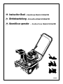 1
1
-
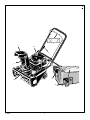 2
2
-
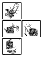 3
3
-
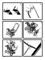 4
4
-
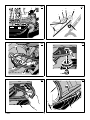 5
5
-
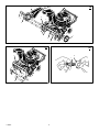 6
6
-
 7
7
-
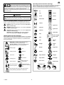 8
8
-
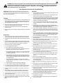 9
9
-
 10
10
-
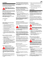 11
11
-
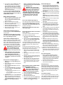 12
12
-
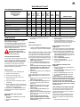 13
13
-
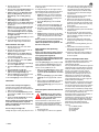 14
14
-
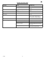 15
15
-
 16
16
-
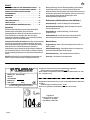 17
17
-
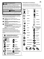 18
18
-
 19
19
-
 20
20
-
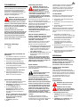 21
21
-
 22
22
-
 23
23
-
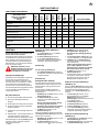 24
24
-
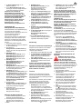 25
25
-
 26
26
-
 27
27
-
 28
28
-
 29
29
-
 30
30
-
 31
31
-
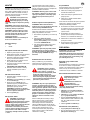 32
32
-
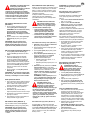 33
33
-
 34
34
-
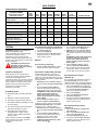 35
35
-
 36
36
-
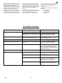 37
37
-
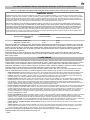 38
38
-
 39
39
-
 40
40
-
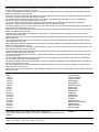 41
41
-
 42
42
-
 43
43
-
 44
44


Murray 621403x61NB Instruction book
- Kategorie
- Schneewerfer
- Typ
- Instruction book
in anderen Sprachen
- English: Murray 621403x61NB
- slovenčina: Murray 621403x61NB
Verwandte Artikel
-
Murray 629104X61 Instruction book
-
-
-
-
-
-
-
-
-
Andere Dokumente
-
Simplicity EU CANADIANA SNOWTHROWER Benutzerhandbuch
-
-
-
-
-
-
-
-
Briggs & Stratton 1696057 Benutzerhandbuch
-