Badger Meter LM OG-TK 100 Instructions For Use And Maintenance Manual
- Typ
- Instructions For Use And Maintenance Manual

®
Badger Meter Europa GmbH
LM OG-Baureihe /
LM OG-Series / Série LM OG
Zählerbaureihe mit elektronischem Zählwerk für
Schmieröl - eichfähig und nicht eichfähig
Oval gear meters with electronic register for
lubricants - approved and non approved
Compteurs électroniques pour le mesurage de
lubrifiants - homologués et non homologués
MONTAGE- UND
BEDIENUNGSANLEITUNG
INSTRUCTIONS FOR
USE AND MAINTENANCE
MANUEL D´INSTALLATION
Mai 2011 / May 2011
LM_OG_BA_98_1105

Inhaltsverzeichnis Seite
LM_OG_BA_98_1105
Deutsch 1
English 9
Franҫais 18
1. Verzichtserklärung ........................................................................................................... 1
2. Grundlegende Sicherheitshinweise ............................................................................... 1
3. Hinweis zur Inbetriebnahme allgemein .......................................................................... 2
4. Garantieerklärung ............................................................................................................ 2
5. Programmierung beim LM OG (CND) und LM OG-HF (CND) ....................................... 3
6. Anschlussdiagramm LM OG-TAE(R) 2 x 100 ................................................................. 4
7. Batteriewechsel ................................................................................................................ 4
8. Standard Korrekturfaktor bei 440 mPas ........................................................................ 5
9. Hinweise für den Betrieb LM OG-A eichfähig ................................................................ 5
9.1 Batterie ....................................................................................................................... 5
9.2 Rückstellung – RESET ............................................................................................... 5
9.3 Unterbrechung des Dosiervorganges ......................................................................... 5
9.4 Funktionsüberwachung .............................................................................................. 5
9.5 Summierzählwerk (LM OG-A) .................................................................................... 5
9.6 LM OG-A: Fehlerüberwachung bei eichfähigem Zähler ............................................. 6
10. Programmierung und Bedienung beim LM OG-A (CND) eichfähig nach PTB ......... 6
11. Zulassungen / Approvals / Approbations ................................................................. 26
12. Herstellererklärung / Manufacturer's declaration / Déclaration du fabriquant ...... 27
13. DIN ISO Zertifikat / DIN ISO certificate / Certificat DIN ISO ..................................... 28

Verzichtserklärung / Grundlegende Sicherheitshinweise Seite 1/28
LM_OG_BA_98_1105
1. Verzichtserklärung
Der Benutzer / Käufer sollte die in dieser Bedienungsanleitung mitgeteilten Informationen
gründlich durchlesen und verstehen, den aufgelisteten Sicherheitswarnhinweisen und
Instruktionen Folge leisten und diese Bedienungsanleitung bei dem Messgerät
aufbewahren, damit sie auch in Zukunft bei Bedarf zur Verfügung steht. Die in dieser
Bedienungsanleitung mitgeteilten Informationen wurden sorgfältig geprüft, sind absolut
verlässlich und stimmen mit dem beschriebenen Produkt überein. Nichtsdestotrotz
übernimmt Badger Meter, Inc. keinerlei Verantwortung bei Ungenauigkeiten, noch kann
Badger Meter, Inc. haftbar gemacht werden für Schäden, die bei Anwendung oder
Gebrauch des beschriebenen Gerätes entstehen. Wird dieses Messgerät in einer anderen
als der von Badger Meter, Inc. genannten Art und Weise verwendet, kann der für dieses
Messgerät gebotene Schutz beeinträchtigt werden und die Garantie wird ungültig.
2. Grundlegende Sicherheitshinweise
Die Geräte sind nach dem Stand der Technik betriebssicher gebaut und geprüft. Sie
haben das Werk in sicherheitstechnisch einwandfreiem Zustand verlassen.
Der Hersteller haftet nicht für Schäden, die aus unsachgemäßem oder nicht
bestimmungsgemäßem Gebrauch folgen.
Die Montage, Elektroinstallation, Inbetriebnahme und Wartung des Messgerätes darf
ausschließlich durch geeignetes Fachpersonal erfolgen. Weiterhin muss das
Bedienungspersonal vom Anlagenbetreiber eingewiesen sein und die Anweisungen
dieser Bedienungsanleitung müssen befolgt werden.
Grundsätzlich sind die in Ihrem Land geltenden Vorschriften für das Öffnen und
Reparieren von elektrischen Geräten zu beachten.
Schutzklasse:
Folgende Geräte haben die Schutzklasse IP 42:
• LM OG-A • LM OG-RFK
• LM OG-CDA • LM OG-T100
• LM OG-CNDA • LM OG-T200
• LM OG-HFT • LM OG-TAEK(A)
• LM OG-P2 Advanced • LM OG-TAE(R) 200
• LM OG-PA • LM OG-TK 100
• LM OG-PK
Folgende Geräte haben die Schutzklasse IP 67:
• LM OG
• LM OG-CND
• LM OG-K
• LM OG-CNDK
• LM OG-HF
• LM OG-HF-CND
Unabhängig von der Schutzklasse müssen alle Geräte vor Tropfwasser, Wasser, Öle,
etc. geschützt werden

Grundlegende Sicherheitshinweise / Inbetriebnahme allgemein / Garanatieerklärung Seite 2/28
LM_OG_BA_98_1105
Installation
Das Gerät nicht auf einem instabilen Platz stellen, wo es fallen könnte.
Das Gerät niemals in der Nähe eines Heizkörpers stellen.
Kabel fern von möglichen Gefahren halten.
Gerät vor Installation erden.
Reinigung
Vor einer Reinigung, Gerät ausschalten und vom Netz entfernen. Mit feuchtem Tuch
reinigen. Keine Reinigungsmittel verwenden.
Reparaturen
Bei Reparaturen Gerät vom Stromnetz trennen.
RoHs
Unsere Geräte sind RoHs-konform.
Batterieentsorgung
Die in unseren Geräten enthaltenen Batterien müssen fachgerecht, gemäß
§12 der BattV sowie gemäß nationalem Recht der einzelnen Länder nach
der EU-Verordnung 2006/66/EG, entsorgt werden.
3. Hinweis zur Inbetriebnahme allgemein
Prüfen, ob die technischen Daten der Anlage mit denen des Schmierölzählers überein-
stimmen, z.B. Anschlüsse, Druck, Durchfluss und Medium. Nachdem das Gerät installiert
ist, muss sichergestellt werden, dass keine Luft, Druckstösse oder Fremdkörper das
Gerät beschädigen können. Alle Anschlüsse auf Leckage prüfen!
Es wird empfohlen, dass nach der Installation mehrere Zapfungen in einen Eichbehälter
gemacht werden. Sollten sich durch den Einsatz verschiedener Ölviskositäten
Abweichungen der Fehlergrenze ergeben, so kann dies sofort vor Ort korrigiert werden.
Somit entfällt ein Ausbau oder Austausch des Geräts.
Bei vorgeprüften Geräten können die Korrekturen von Installateuren oder auch
Eichbeamten durchgeführt werden.
4. Garantieerklärung
Hiermit garantieren wir, dass die von uns hergestellten und gelieferten Durchfluss-
messgeräte sowie Ersatzteile materialfehlerfrei sind. Sie erhalten eine Garantie von 18
Monaten nach Lieferdatum oder von 12 Monaten nach Installation auf unsere Produkte.
Sollten in diesem Zeitraum Materialfehler bei unseren Produkten auftreten, werden diese
Produkte von uns kostenlos repariert bzw. ersetzt. Hierzu soll der Käufer dem Hersteller
über den Materialfehler innerhalb von 10 Tagen nach seiner Feststellung schriftlich
informieren und die Produkte zur Entlastung des Herstellers zur Reparatur zurück-
schicken. Badger Meter übernimmt keine Haftung für Schäden, die weder auf Handlungs-
missbrauch oder Missachten der dem Produkt beigefügten Bedienungsanleitung nach
Wareneingang noch auf Frachttransport zurückzuführen sind.
Das Nicht-Beachten dieser grundlegenden
Sicherheitshinweise kann zu Gerätefehlern
führen oder ernste Verletzungen verursachen.
ACHTUNG

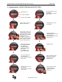
Programmierung beim LM OG (CND) und LM OG-HF (CND) Seite 3/28
LM_OG_BA_98_1105
3x „Total“, 3x „Reset“
hintereinander drücken, dann
gelangt man in den
Programmiermodus. Die
Maßeinheit „L“ (Liter) blinkt
und kann durch Drücken der
„Reset“ Taste verändert
werden in L, GAL, QT oder
PT. Bestätigung der
Maßeinheit durch Drücken
der „Total“ Taste.
5. Programmierung beim LM OG (CND) und LM OG-HF (CND)
Änderungen vom K-Faktor:
Einmaliges Drücken der „Total“
Taste.
Die zu verändernde Zahl wird
nun durch Blinken angezeigt
und kann mit „Reset“ verändert
werden. Um die nächste Stelle
zu verändern, „Total“ drücken.
Einschalten des Zählers
mit einmaligem Drücken
der „Total
“
Taste.
„Total“ Rückstellbar
„Total“ nicht
Rückstellbar
Maßeinheit
Um die Programmierung zu
speichern, müssen beide
Tasten gleichzeitig gedrückt
werden.
Danach fällt der Zähler in
den Schlafmodus.
Schlafmodus
Die 5. Stelle kann jetzt
verändert werden.
Die 4. Stelle kann jetzt
verändert werden.
Um zu nächsten Stelle zu
gelangen „Total“ drücken.
Die 2. Stelle kann jetzt
verändert werden.
Um zur nächsten Stelle
zu gelangen, „Total“
drücken.
Nach Schlafmodus
„Total“ Taste drücken
und es erscheint der
„normale“ Anzeige-
modus.
Die 3. Stelle kann jetzt
verändert werden.
Um zur nächsten Stelle
zu gelangen, „Total“
drücken.
3 Sekunden „Reset“
gedrückt halten, dann
erscheint die
Checksumme.

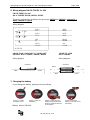
Anschlussdiagramm LM OG-TAE(R) 2 x 100 / Batteriewechsel Seite 4/28
LM_OG_BA_98_1105
R1K2
1K2R
AUSG.1
OUT 1
OUT 2
AUSG.2
0V
GND
6-24 VDC
SUPPLY
OG-TAER 200
GRÜN
GREEN
WHITE
WEISS
BROWN
BRAUN
YELLOW
GELB
Reedschalte
r
braun
weiss
gelb
grün
Reedschalte
r
weiss braun
6. Anschlussdiagramm LM OG-TAE(R) 2 x 100
LM OG-TAE(R) 2 x 100
Art. Nr. 102128, 102130, 102131, 103132
Bei den Geräten 102128
und 102130 ändert sich die Anschlussbelegung auf: Kanal 1 =
weiss; Kanal 2 = grün
Anschlussdiagramm
Art. Nr. LM OG-T 100 / LM OG-HFT 1“ / LM OG-HFT LM OG-T 2 x 100
66,75 PPL Art. Nr. 102101 / 102920 / 102915 Art. Nr. 102106
Anschlussdiagramm Anschlussdiagramm
7. Batteriewechsel
Wird die Batterie getauscht, so folgen Sie einfach der Bildbeschreibung.
Batterie: Lithium CR123A
Bild 1: Lösen des
Batteriedeckels
Bild 2: Herausnehmen
der Batterie
Bild 3: Neue Batterie
einsetzen, danach die
Resettaste drücken, um die
Funktion des Zählwerks zu
prüfen
Bild 4: Einsetzen des
Batteriedeckels, danach
Batteriedeckel festschrauben

Standard Korrekturfaktor bei 440 mPas / Hinweis für den Betrieb LM OG-A eichfähig Seite 5/28
LM_OG_BA_98_1105
8. Standard Korrekturfaktor bei 440 mPas
a) LM OG = 1,0000
b) LM OG-HF = 1,4700
9. Hinweise für den Betrieb LM OG-A eichfähig
9.1 Batterie
Bei allen Zählern der LM OG-A Baureihe kann die Batterie ersetzt
werden, indem man den Deckel auf der Frontseite des Zählwerks
öffnet. Dabei entfällt eine Neuprogrammierung, da die Program-
mierung erhalten bleibt. Bei leerer Batterie erscheint ein Batterie-
symbol zum Batteriewechsel. Batterie-Typ beim eichfähigen LM OG-A:
Lithium CR ½ AA.
9.2 Rückstellung – RESET
Die Anzeige des Dosierzählerspeichers kann durch Betätigen der RESET-Taste auf
NULL gesetzt werden. Eine Rückstellung während eines laufenden Arbeitsvorgangs
ist nicht möglich. Der Summierzählerspeicher ist nur über die interne Program-
mierung rückstellbar.
9.3 Unterbrechung des Dosiervorganges
Durch Entsperren bzw. Freigeben des Betätigungshebels wird der Dosiervorgang
unterbrochen. Bei erneutem Betätigen wird der Dosiervorgang an der
Unterbrechungsstelle fortgesetzt, wenn nicht vorher die RESET-Taste gedrückt wird.
Die Anzeige bleibt während der Dauer der Unterbrechung stehen. Wird der
Dosiervorgang extern vom Schmierölzähler, z.B. durch Ausfall der Förderpumpe,
unterbrochen, geschieht dasselbe wie bei der normalen Unterbrechung.
9.4 Funktionsüberwachung
Der RESET-Befehl löst automatisch einen Selbsttest des Zählwerks aus. Das LCD
zeigt alle Anzeigesegmente "8“ an. Volumenimpulse, die während der Selbsttest-
Phase einlaufen, werden registriert und ausgewertet. Alle anderen gespeicherten
Werte wie Masseinheit und Korrekturfaktor werden geprüft. Erst, wenn die Werte
übereinstimmen, wird eine normale Messung durchgeführt. Falls ein oder mehrere
Werte nicht übereinstimmen, wird dies durch eine Reihe von Strichen (- - - -)
angezeigt und die Zählfunktion stillgelegt. Ein „Reset“ wird durch kurzes
Herausnehmen der Batterie durchgeführt, somit ist das Zählwerk wieder
funiktionsfähig.
Das gemessene Volumen bzw. alle Reedschalter-Messimpulse werden in jedem Fall
ausgewertet und zu dem zuletzt angezeigten Dosiervolumen hinzuaddiert, solange
nicht durch Drücken der RESET-Taste ein neuer Dosiervorgang ausgelöst wird.
9.5 Summierzählwerk (LM OG-A)
Die Betätigung der TOTAL-Taste bewirkt die Anzeige des Summierspeicherwertes,
aber nur, wenn keine Volumenimpulse registriert werden (siehe Kalibrier- oder
Korrekturfaktor).
Der werkseitig programmierte Korrekturfaktor ergibt sich bei der Genauigkeitsprüfung
des Grundzählers mit aufgesetztem elektronischem Anzeigewerk.

Hinweis für den Betrieb LM OG-A eichfähig / Programmierung und Bedienung... Seite 6/28
LM_OG_BA_98_1105
Beispiel: Abgegebene Menge: 4,2 Liter; Angezeigte Menge: 4,0 Liter; Korrekturfaktor
k = 4,2/4,0 = 1,05
Werden die TOTAL und die RESET-Taste in dieser Reihenfolge gleichzeitig betätigt,
wird der einprogrammierte Korrekturfaktor solange angezeigt, wie beide Tasten
gedrückt bleiben.
Sobald Volumensignale eingehen, werden die Tastaturbefehle ignoriert!
Sobald Impulse auflaufen, ist die Tastatur ausser Funktion!
9.6 LM OG-A: Fehlerüberwachung bei eichfähigem Zähler
Während der Messung überwacht der MIKROPROZESSOR die Phasenlage der
beiden Reedschalter (30° bis 150° Phasenverschiebung).
Pulsfolgefehler
:
Wenn nach einem RESET mehr als zwei Phasenfehler registriert werden, blinkt die
LCD-Anzeige mit 1 Hz bzw. im 1-Sekunden-Takt und signalisiert so, dass die erlaubte
Fehlergrenze überschritten wurde. Fehlimpulse und Warnanzeige werden durch
Ausführen eines RESET-Befehls gelöscht. Kann das Blinken nicht gelöscht werden,
liegt ein Defekt vor und das Zählwerk muss ausgetauscht werden.
Das Blinken kann z.B. auch durch eine kurzzeitige Rückwärtsströmung beim
Anfahren oder bei schlecht entlüfteter Ölleitung auftreten (Druckstösse). Dies kann
durch Einbau eines geeigneten Rückflussverhinderers ausgeschlossen werden.
Fehler in den gespeicherten Variablen
: (Korrekturfaktor, Masseinheit)
Diese Fehler werden durch eine Reihe von Strichen (- - - -) angezeigt und kann durch
kurzes entfernen der Batterie beseitigt werden.
10. Programmierung und Bedienung beim LM OG-A (CND) eichfähig nach
PTB, BEV
LM OG-A (CND)
Die Masseinheit und der Korrekturfaktor können programmiert werden.
Zum Programmieren wird ein Taster auf der Unterseite des elek-
tronischen Zählwerks für 3 Sekunden gedrückt. Der Programmiertaster ist
nur zugänglich, nachdem das elektronische Zählwerk von der Mess-
kammer abgenommen wurde. Dazu muss bei der eichfähigen Ausführung
eine plombierte Schraube gelöst werden, es dürfen nur befugte Personen
diesen Eingriff vornehmen. Eine Nacheichung durch das Eichamt ist
zwingend erforderlich.
Programmierablauf LM OG-A (CND)
(a) Durch Betätigen des Programmierschalters werden die aktuellen Zustände von
Korrekturfaktor und Masseinheit auf dem Display angezeigt. Vor dem ersten
Programmieren werden dargestellt, zum Beispiel:
- Korrekturfaktor = 1,0000 bei LM OG
- Masseinheit L
Der Korrekturfaktor kann im Bereich von 0,0000 bis 9,9999 programmiert
werden. Das Komma steht immer hinter der ersten Stelle. Dieses Komma
wird bei der Masseinheit Liter als Komma (,) und bei allen anderen
Masseinheiten als Punkt (.) dargestellt.

Programmierung und Bedienung beim LM OG-A (CND) eichfähig nach PTB, BEV Seite 7/28
LM_OG_BA_98_1105
(b) Das Zeichen für die Masseinheit blinkt sofort nach Betätigen des Program-
miertasters. Alle anderen Zeichen werden konstant angezeigt. Das Blinken macht
den veränderbaren Wert kenntlich. Jeder Tastendruck auf RESET schaltet nun die
Masseinheit weiter, und zwar in der Reihenfolge (QT) – GAL – L – PT.
Nach Auswahl der benötigten Masseinheit wird dieser Programmteil durch Betätigen
der TOTAL-Taste verlassen. Gleichzeitig wird die so gewählte Masseinheit als
aktueller Wert vorgemerkt.
(c) Der zuletzt geschaltete Wert wird durch Betätigen der TOTAL-Taste im Programm als
aktueller Wert vorgemerkt.
(d) Jede Betätigung der RESET-Taste schaltet den Wert von "0“ bis "9" um jeweils 1
weiter. Der gewünschte Wert wird durch Bestätigen der TOTAL-Taste im Programm
vorgemerkt.
(e) Das Abschliessen der Programmierung der ersten Stelle des Korrekturfaktors durch
Betätigen der TOTAL-Taste schaltet auf die Programmierung der zweiten Stelle des
Korrekturfaktors um. Sie blinkt im 0,3 s-Takt. Jede Betätigung der RESET-Taste
schaltet den Wert von "0" bis "9" um jeweils 1 weiter. Der gewünschte Wert wird
durch Bestätigen der TOTAL-Taste im Programm vorgemerkt.
(f) Der in Abschnitt e) beschriebene Vorgang zur Programmierung der zweiten Stelle
des Korrekturfaktors wird in gleicher Weise zur Programmierung der restlichen 3
Stellen durchgeführt.
(g) Ist der geforderte Wert bereits eingestellt gewesen, kann durch Betätigen der TOTAL-
Taste unmittelbar auf die nächste Stelle übergegangen werden. Der angezeigte,
blinkende Wert wird dann so im Programm vorgemerkt.
(h) Wird die Programmierung an einer beliebigen Stelle durch die Freigabe des
Programmiertasters unterbrochen, dann werden die bis dahin eingegebenen neuen
Werte und die ggf. nicht veränderten alten Werte als aktueller Programmierstand
übernommen. Die LCD-Anzeige blinkt dreimal und zeigt dabei die nunmehr
gespeicherten Programmwerte zur Bestätigung an.
(i) Mit der Speicherung des Programmwertes gemäss Abschnitt h) multipliziert der
Mikroprozessor den damit festgelegten Korrekturwert mit dem durch
Programmierpunkt b) festgelegten Quellenwert. Der so gewonnene Faktor stellt das
korrekte Volumeninkrement dar, das einem Eingangsmessimpuls entspricht. Dieser
Wert und die Masseinheit werden sicherheitshalber einfach redundant gespeichert.
(j) Der Inhalt des Summierzählspeichers bleibt auch bei einer Umprogrammierung
erhalten, solange die Masseinheit nicht geändert wird. Wird die Programmierung in
Punkt h) mit einer neuen Masseinheit abgeschlossen, erfolgt automatisch die
Rücksetzung des Summierzählspeichers auf Null.
Nach Freigabe des Programmiertasters schaltet der Mikroprozessor alle Funktionen,
einschliesslich LCD-Anzeige, bis auf die Datenspeicherung, ab. Dieser Zustand bleibt
solange erhalten, bis entweder der RESET oder der TOTAL-Befehl gegeben wird.
Zum erneuten Abschalten muss die Programmiertaste erneut betätigt werden.
Der Programmierschalter selbst ist ausser Betrieb, wenn der Mikroprozessor in der
vorgenannten Weise abgeschaltet ist.

Programmierung und Bedienung beim LM OG-A (CND) eichfähig nach PTB, BEV Seite 8/28
LM_OG_BA_98_1105
Beispiel – Korrektur der Messgenauigkeit für LM OG/LM OG-A/LM OG-HF
Tatsächlich abgegebene Menge: 1,6 l / Angezeigte Menge: 1,52 l / Korrekturfaktor k =
1,6/1,52 = 1,0526
(a) Anzeige des bisher programmierten Korrekturfaktors durch Drücken und Halten der
TOTAL-Taste und gleichzeitiges Drücken der RESET-Taste. Beispiel: 0,9950
(b) Errechnen des neu zu programmierenden Korrekturfaktors:
0,9950 x 1,0526 = 1,0473

Contents Page 9
LM_OG_BA_98_1105
1. Disclaimer ...................................................................................................................... 10
2. Basic safety recommendations ................................................................................... 10
3. Before putting into operation ....................................................................................... 11
4. Warranty ......................................................................................................................... 11
5. Programmation of LM OG (CND) and LM OG-HF (CND) ............................................ 12
6. Wiring diagram LM OG-TAE(R) 2 x 100 ....................................................................... 13
7. Changing the battery .................................................................................................... 13
8. Standard correction factor at 440 mPas ..................................................................... 14
9. Details of unit operation LM OG-A approved ............................................................. 14
9.1 Battery ................................................................................................................... 14
9.2 RESET ................................................................................................................... 14
9.3 Interruption of batch process ................................................................................. 14
9.4 Functional control .................................................................................................. 14
9.5 Totalizer (LM OG-A) .............................................................................................. 14
9.6 LM OG-A: Monitoring of false pulses ..................................................................... 15
10. Programming and use of LM OG-A (CND) .................................................................. 17
11. Approvals ...................................................................................................................... 26
12. Manufacturer's declaration .......................................................................................... 27
13. DIN ISO certificate ......................................................................................................... 28

Disclaimer / Basic safety recommendations Page 10/28
LM_OG_BA_98_1105
1. Disclaimer
The user/purchaser is expected to read and understand the information provided in this
manual, follow any listed safety precautions and instructions and keep this manual with
the equipment for future reference. The information in this manual has been carefully
checked and is believed to be entirely reliable and consistent with the product described.
However, no responsibility is assumed for inaccuracies, nor does Badger Meter, Inc.
assume any liability arising out of the application and use of the equipment described.
Should the equipment be used in a manner not specified by Badger Meter, Inc., the
protection provided by the equipment may be impaired and the warranty voided.
2. Basic safety recommendations
Before installing or using this product, please read this instruction manual thoroughly.
Only qualified personnel should install and/or repair this product. If a fault appears,
contact your distributor.
Installation
Do not place any unit on an unstable surface that may allow it to fall.
Never place the units above a radiator or heating unit.
Route all cabling away from potential hazards.
Isolate from the mains before removing any covers.
Power connection
Use only the type of power source suitable for electronic equipment. If in doubt, contact
your distributor. Ensure that any power cables are of a sufficiently high current rating.
All units must be earthed to eliminate risk of electric shock.
Failure to properly earth a unit may cause damage to that unit or data stored within it.
Protection class
Following devices have protection class IP 42:
• LM OG-A • LM OG-RFK
• LM OG-CDA • LM OG-T100
• LM OG-CNDA • LM OG-T200
• LM OG-HFT • LM OG-TAEK(A)
• LM OG-P2 Advanced • LM OG-TAE(R) 200
• LM OG-PA • LM OG-TK 100
• LM OG-PK
Following devices have protection class IP 67:
• LM OG
• LM OG-CND
• LM OG-K
• LM OG-CNDK
• LM OG-HF
• LM OG-HF-CND
All devices have to be protected against dripping water, water, oils, etc.
Setup & operation
Adjust only those controls that are covered by the operating instructions. Improper
adjustment of other controls may result in damage, incorrect operation or loss of data.

Basic safety recommendations / Before putting into operation / Warranty Page 11/28
LM_OG_BA_98_1105
Cleaning
Switch off all units and isolate from mains before cleaning.
Clean using a damp cloth. Do not use liquid or aerosol cleaners.
Repair of faults
Disconnect all units from power supply and have it repaired by a qualified service person if
any of the following occurs:
• If any power cord or plug is damaged or frayed
• If a unit does not operate normally when operating instructions are followed
• If a unit exposed to rain/water or if any liquid has been spilled into it
• If a unit has been dropped or damaged
• If a unit shows a change in performance, indicating a need for service.
RoHs
Our products are RoHs compliant.
Battery disposal
The batteries contained in our products need to be disposed of as per your
local legislation acc. to EU directive 2006/66/EG.
3. Before putting into operation
Please check that the technical data of the installation match with those of the lube meter,
for example connections, pressure, flow range and medium. Once the meter has been
installed, please make sure that no air, pressure shocks or particles can damage the
meter. Please check all connections to leakage. After the installation we recommend to do
several transactions into an approved tank. Should the use of different oil viscosities show
discrepancies by the error limit, this can immediately be corrected at the site. This avoids
to remove or exchange the meter. In case of pretested meters can corrections be carried
out by technicians or officials of the National Weights and Measure Laboratory.
4. Warranty
Badger Meter warrants meters and parts manufactured by it and supplied hereunder to be
free from defects in materials and workmanship for a period of 18 months from date of
shipment or 12 months from date of installation, whichever period shall be shorter. If
within such period any meters or parts shall be proved to Seller´s satisfaction to be
defective, such meters or parts shall be repaired or replaced at Seller´s option. Seller´s
obligation hereunder shall be limited to such repair and replacement and shall be
conditioned upon Seller´s receiving written notice of any alleged defect within 10 days
after its discovery and, at Seller´s option, return of such meters or parts to Seller, f.o.b. its
factory. THE FOREGOING WARRANTY IS EXCLUSIVE AND IN LIEU OF ALL OTHER
EXPRESS OR IMPLIED WARRANTIES WHATSOEVER INCLUDING BUT NOT LIMITED
TO IMPLIED WARRANTIES (EXCEPT OF TITLE) OF MERCHANTABILITY AND
FITNESS FOR A PARTICULAR PURPOSE. Badger Meter shall not be liable for any
defects attributable to acts or omissions of others after shipment, nor any consequential,
incidental or contigent damage whatsoever.
Failure to adhere to these safety instructions
may result in damage to the product or serious
bodily injury.

Programmation of LM OG (CND) and LM OG-HF (CND) Page 12/28
LM_OG_BA_98_1105
Press 3 times „Total“ and
3 times „Reset“ to access
the programmation mode.
Measuring unit “L” (liter) is
flashing and can be
changed in L, GAL, QT or
PT when pressing “Reset”.
Press “Total” to confirm
the new measuring unit.
5. Programmation of LM OG (CND) and LM OG-HF (CND)
Press „Total“ one time to
switch on the meter.
„Total“ resettable
„Total“ not resettable
Measuring unit
Press both buttons
simultaneously to save the
programmation.
The meter then goes to the
sleeping mode.
The fifth figure can now
be changed.
The fourth figure can now
be chanced.
To access the next figure,
press “Total”.
Press “Total” one time
to change the k-factor.
The figure to be
changed is flashing
and can be modified
with “Reset”.
To change the next
figure, press “Total”.
The second figure can
now be chanced.
To access the next figure,
press “Total”.
The third figure can now
be chanced.
To access the next figure,
press “Total”.
After the sleeping mode,
please press „Total“ to
show the „normal“
display mode.
Sleeping mode
Press „Reset“ during 3
seconds and the
register displays the
check sum.

Wiring diagram LM OG-TAE(R) 2 x 100 / Changing the battery Page 13/28
LM_OG_BA_98_1105
R1K2
1K2R
AUSG.1
OUT 1
OUT 2
AUSG.2
0V
GND
6-24 VDC
SUPPLY
OG-TAER 200
GRÜN
GREEN
WHITE
WEISS
BROWN
BRAUN
YELLOW
GELB
6. Wiring diagram LM OG-TAE(R) 2 x 100
LM OG-TAE(R) 2 x 100
Art. n° 102128, 102130, 102131, 103132
The wiring configuration is different for the meters 102128
and 102130 to: channel 1 =
white; channel 2 = green
Wiring diagram
LM OG-T 100 / LM OG-HFT 1“ / LM OG-HFT LM OG-T 2 x 100
66,75 PPL Art. n° 102101 / 102920 / 102915 Art. n° 102106
Wiring diagram Wiring diagram
7. Changing the battery
If you change the battery, please proceed as follows:
Battery: Lithium CR123A
Picture 1: Loosen
the battery cover
Picture 2: Take out
the battery
Picture 3: Insert the new
battery and press the reset
button to check the function
of the register
Picture 4: Insert the
battery cover, then screw
the battery
Reedswitch
yellow
white
brown
green
Reedswitch
white brown

Details of unit operation LM OG-A approved Page 14/28
LM_OG_BA_98_1105
8. Standard correction factor at 440 mPas
a) LM OG = 1,0000
b) LM OG-HF = 1,4700
9. Details of unit operation LM OG-A approved
9.1 Battery
The battery is exchangeable in all meters of the LM OG-A series while
opening the cover on the front of the register. A new programmation is
not necessary as the programmation does not get lost. Battery type of
approved meter LM OG-A: Lithium CR ½ AA
A battery symbol is warning when battery change is necessary.
9.2 RESET
The display of the batch register memory can be put to ZERO by pushing the RESET
button. A reset is not possible during a batch process. Resetting of the totalizer is
only possible through internal programming.
9.3 Interruption of batch process
By releasing the meter trigger, the batch process is interrupted. When pulled again,
the batch process will be continued at the very point where it was interrupted, unless
the RESET button has been pushed in the meantime. The display will remain
unchanged during the interruption. If the batch process is interrupted by external
source – e. g. failure of a transfer pump – the procedure is the same.
9.4 Functional control
In normal operation, the register board totalizes flow in the lube meter by sensing
reed switch actions, as described below. The batch display may be reset to zero by
momentarily pressing the RESET button on the front panel. This action will set the
batch accumulator to zero and cause the register to enter a selftest mode, as
described below. For the self test, it is necessary that the display is activated with all
numerics set to “8” and all other indicators set to “on” for a period of 0,8 seconds. If
flow or reed switch action takes place during the self test period, the resultant pulses
are processed as normal flow accumulations. This accumulation of flow can only be
reset by pressing the RESET button, or by reprogramming the register for a different
unit of measure. During the self test period, the meter will compare the double
redundant storage of the correction factor, the unit of measure and direction of
rotation. If two or more values do not correspond, the register will show a series of
dashes (- - - -) and will become inoperative.
If flow sensing or reed switch action is present at any time and it is not preceded by a
pressing of the RESET button, the flow accumulations will be added to the value
already present in the batch accumulator.
9.5 Totalizer (LM OG-A)
Pressing the TOTAL button will cause the accumulator memory value to be displayed,
for as long as the button is being pressed, but only as long as no volume pulses are
coming in (see also calibration or correction factor). The factory programmed
correction factor results from accuracy testing of bare meter with the mounted
electronic register:

Details of unit operation LM OG-A approved Page 15/28
LM_OG_BA_98_1105
Example:
Quantity dispensed: 4,2 litres, Quantity displayed: 4,0 litres, Correction factor k:
4,2/4,0 = 1,05
Pressing the TOTAL and the RESET button simultaneously in this sequence will
cause the programmed correction factor to be displayed, as long as both buttons are
depressed.
As soon as volume signals come in, all keyboard commands will be ignored!
As soon as pulses are totalized, the keypad is out of function!
9.6 LM OG-A: Monitoring of false pulses
During measurement, the microprocessor controls the phase position of both reed
switches (30° to 150° phase shift).
Errors caused by incorrect phase sequence:
If more than two (2) phase errors are noted after a RESET, the LCD display is
flashing slowly (1 second interval). This type of error is resettable by depressing the
RESET button.
If it is nor possible to stop the flashing, there is another fault and the register has to
be exchanged.
The flashing can e. g. also be caused by a short-time reverse flow when starting up
the oil dispense system, or by an insufficiently areated oil pipe (pressure shocks).
This can be prevented by installing an appropriate non-return valve.
Errors in stored variables
: (i.e. correction factor, unit of measure, direction of rotation)
These errors are indicated by a series of dashes across the display and are not
resettable. The register has to be removed from service.
Installation procedure LM OG
The meter series LM OG is equipped with a (1/2", 3/4", 1”) BSP female thread on the
inlet side. In order to obtain a leakage free connection from the meter to the hose, the
hose end must have an appropriate BSP male thread.
We recommend to proceed as follows before screwing in:
1. Clean both threads from fat.
2. Brush the male thread at the hose with liquid sealant (e.g. Eurolock 310100 or
equivalent selaing of other manufacturers). Please be careful that no sealing gets
into the meter.
3. Screw both parts together.
Do not overtighten the screw connection, otherwise the swivel of the meter could
be damaged.
4. The instruction of the sealing manufacturer should be absolutely followed.
5. The meter mounting should only be carried out by authorized specialist staff.
The right selection of the components as well as the mounting in accordance with the
regulations is in the responsibility of the user.

Programming and use of LM OG-A (CND) Page 16/28
LM_OG_BA_98_1105
10. Programming and use of LM OG-A (CND)
LM OG-A (CND)
The units of measure and the correction factor can be programmed. A
momentary contact programming button is located on the bottom of the
register, which is accessible only when the register has been removed
from the meter. Removing the register from the meter requires the
removal of a sealed register mounting screw. This seal has to be
restamped by the Office of Weights and Measures. Activating the
programming button (by pressing it for 3 seconds) will immediately
force the register into the program mode. Any reed switch activity during the program
mode will cause the register to exit from the program mode.
Programming procedure LM OG-A (CND)
a) Upon initial activation of the board mounted program button, the register
will display for example:
- Correction factor = 1,0000 LM OG
- Unit of measure L
The programmable correction factor has a range of 0,0000 to 9,9999. The decimal
point is always located after the first digit. When “litres” is programmed or selected as
the unit of measure, the decimal point will immediately change to a comma and will
remain so as long as “litres” is the selected or programmed unit of measure. (Default
values are 0,0000, “clockwise” and “QT”, if no values have been programmed
previously).
b) The unit of measure indicator in the display will immediately begin flashing at 0,3
second rate, all other display action being constant, indicating that the unit of
measure is available for change. With each depression of the RESET button, the unit
of measure indicator will step through its individual four values in sequence, which are
(QT) – GAL – L – PT.
c) Depressing the TOTAL button will store the presently displayed data as the current
value for the new setting.
d) Any depression of the RESET button will increment the first or left most digit of the
correction factor. Depressing the TOTAL button will store the presently displayed
value as the current value.
e) This depression of the TOTAL button in step d) will initiate flashing action of the next
successive digit in the correction factor and allow it to be scrolled with the RESET
button. All other digits will remain constant. This successive programming action will
be continued for the remaining four digits of the correction factor. The four right most
digits of the correction factor will be allowed to assume the full range of values from
zero (0) to nine (9). Each depression of the TOTAL button will store the value present
on the display as the current value for that digit.
f) Successive depressions of the TOTAL button will continue to enable flashing and
scrolling of the digits or unit of measure in sequence. The action will continue even if
a particular unit of measure or correction digit has already been selected by a
previous action.
g) If no scrolling by the RESET button is undertaken between depressions of the TOTAL
button, then the present value of a digit or unit of measure as displayed will be utilized
as the current value for the digit or unit of measure.

Programming and use of LM OG-A (CND) Page 17/28
LM_OG_BA_98_1105
h) Removing pressure from the program button at any time during the programming
process will force the values presently displayed (just entered or previously entered)
to be stored as permanent values. The storage of the new values will be indicated by
the entire display flashing three times to acknowledge the process.
i) During the process of the programming operation as per item h) the seed number in
the memory of the mP is multiplied by the correction factor. The result is the proper
batch volume increment which corresponds to one input pulse. It will be stored as well
as the unit of measure with simple redundancy to assure security.
j) The contents of the totalizer counter will be kept during reprogramming, as long as
the unit of measure is not changed. If programming as described under h) is
completed with a new unit of measure, the totalizer counter will automatically be
zeroed. It does not matter if the units of measure have been toggled during the
course of the programming only the final stored value is important.
After release of the program button, the microprocessor will switch off all functions,
incl. LCD display, only the data storage will remain constant. This status will remain
unchanged until the RESET or TOTAL button are pressed. A new depressing of the
program button enables a new switch off.
The program button does not work after the microprocessor has been switched off as
described above.
Example: Correction of the accuracy for LM OG/LM OG-A/LM OG-HF
Quantity dispensed: 1,6 l
Quantity displayed: 1,52 l
Correction factor k = 1,6/1,52 = 1,0526
a) Display current correction factor by pressing and holding TOTAL and RESET buttons
simultaneously.
Example: 0,9950 (Make a note of this number)
b) Calculation of the new correction factor:
0,9950 x 1,0526 = 1,0473

Index Page 18
LM_OG_BA_98_1105
1. Déclaration de renonciation ............................................................................................ 19
2. Mesures de sécurité ........................................................................................................ 19
3. Avant la mise en service ................................................................................................. 20
4. Garantie ............................................................................................................................ 20
5. Programmation du compteur LM OG (CND) et LM OG-HF (CND) ................................ 21
6. Installation électrique LM OG-TAE(R) 2 x 100 ............................................................... 22
7. Changement de pile ......................................................................................................... 22
8. Facteur de correction standard pour 440 mPas ............................................................ 22
9. Service .............................................................................................................................. 23
9.1 Batterie
............................................................................................................................................................................................................................................................................................................................................................................................................................................................................................................................................................................................................................................................................................................................................................................................................................................................................................................................................................................................................................................................................................................................................................................................................................................23
9.2 Remise à zéro .......................................................................................................... 23
9.3 Interruption comptage .............................................................................................. 23
9.4 Contrôle de fonctions ............................................................................................... 23
9.5 Totalisateur (LM OG-A) ............................................................................................ 23
9.6 LM OG-A: Contrôle erreur sur compteurs homologués ........................................... 24
10. Programmation et utilisation du compteur LM OG-A (CND) ...................................... 24
11. Approbations .................................................................................................................. 26
12. Déclaration du fabriquant ............................................................................................. 27
13. Certificat DIN ISO ........................................................................................................... 28
Seite wird geladen ...
Seite wird geladen ...
Seite wird geladen ...
Seite wird geladen ...
Seite wird geladen ...
Seite wird geladen ...
Seite wird geladen ...
Seite wird geladen ...
Seite wird geladen ...
Seite wird geladen ...
Seite wird geladen ...
Seite wird geladen ...
-
 1
1
-
 2
2
-
 3
3
-
 4
4
-
 5
5
-
 6
6
-
 7
7
-
 8
8
-
 9
9
-
 10
10
-
 11
11
-
 12
12
-
 13
13
-
 14
14
-
 15
15
-
 16
16
-
 17
17
-
 18
18
-
 19
19
-
 20
20
-
 21
21
-
 22
22
-
 23
23
-
 24
24
-
 25
25
-
 26
26
-
 27
27
-
 28
28
-
 29
29
-
 30
30
-
 31
31
-
 32
32


Badger Meter LM OG-TK 100 Instructions For Use And Maintenance Manual
- Typ
- Instructions For Use And Maintenance Manual
in anderen Sprachen
- English: Badger Meter LM OG-TK 100
- français: Badger Meter LM OG-TK 100
Verwandte Artikel


Andere Dokumente
-
Allnet ALL3690 Bedienungsanleitung
-
Zenner pulse detection Installationsanleitung
-
CARLO GAVAZZI UDM 60 Bedienungsanleitung
-
STIEBEL ELTRON CND 75-200 Operation Instruction
-
Foster FHC291XM, FHC540XM Operation Instructions Manual
-
Edirol R-1 Bedienungsanleitung
-
Mettler Toledo InPro 7100-VP Series Conductivity Electrode Installationsanleitung
-