WAGO 852 Series Operating And Assembly Instructions
- Typ
- Operating And Assembly Instructions

Mounting and Instal lation Instructio ns
Keep this insert!
WAGO Kontakt te c h nik GmbH & Co. KG
Hansas t r. 27
D- -324 2 3 Minde n
www.wago.com
Industrial ETHERNET Switches Series 852
852- 101 5- Port 100BA S E- TX
852- 102 8- Port 100BA S E- TX
852- 103 8/2 Port 100BASE- TX/FX
852- 103/040- 000 8/2 Port 100BASE- TX/FX T
(Operating temperature -40 °C ... +70 °C)
852- 104 7/2- Port 100BASE- TX/FX Managed
852- 104/040- 000 7/2- Port 100BASE- TX/FX Managed T
(Operating temperature -40 °C ... +70 °C)
Befo r e instal l a tio n and operatio n, please read the
follo wing thoroug hl y and caref u l l y. Incorrec t
install a tio n may compromise safety in the event of a
failure.
1. Safety Information
Please obser v e the fol l o wing:
− the applicabl e laws, standa r d s and regu l a tio n s
− the state of the art at the time of install a tion
− the operating instructions
− the engineering regula tion s
− the fact that operating instruc tio n s can only mention
genera l regulatio n s and that these must be observ ed
Bef o r e start- up, please check the device for any damage that
may have occur red during shipping. The device must not be put
into operatio n if there is mechanica l damage presen t.
The devices described in these instru c tio n s must only be
install e d by a qualified elect rician and must only be instal l e d
in elec t ric a l switchgea r or in sealed enclo su r e s . Improper use,
or failure to fol l ow this application note, will rende r the
warra n ty or guaran te e null and void.
The devices must only be instal l e d in dry, indoor areas.
Do not install the devices on or in the vicinity of easily
inflammable materials.
2. Package Checklist
− 852- 10x Industrial Switch
−Din- Rail kit
− Mounting and Installation Instructions
−RJ45 to DB9 (femal e) cable (for 852- 104 only)
3. Hardware Installation
1. Remove the device from its packing. Connec t the 9- 48V
DC (redundan t) power to the power terminal block
input on top panel. If required can connec t relay
output for an alarm condition. 6- pin terminal block of
the 852- 10x series offer s dual DC power conne c tio n
and a relay output for any alarming condition.
Connec t the DC power cable for primary powe r (PWR)
and if required redundan t power (RPS) as well. The
terminal block also provides an alarm output.
Use the DIP switch setting to enable the alarm
func tions for the relevan t activity. If the alarm is
connec t e d but DIP switc h is disabled, the alarm output
will not work.
2. Connec t the Fiber / Ethe r n et (RJ45) port to the
netwo rking device. See the LNK/ACT LED to confirm if
the connectio n is established.
3. Use serial port to perfo rm out of band managemen t in
852- 104.
4. See the DIP switch on top panel to enable / disable the
required features for appropriate usage.
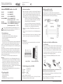
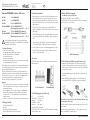
4. Location
The 852- 10x can be placed on a desktop or horizont a l surfa ce
and Din- Rail mounted.
6- pin Terminal Block Din- Rail mounting
5. Default Management (852- 104only)
IP: 192.168.0.254
Subne t Mask: 255.255.255.0
Gateway: 192.168.0.1
User Name: admin
Passwo rd: Null/ empty
6. RJ45 to DB9 Pin Assignment
(for RS- 232 console port) 852- 104
852- 104 offer s 8- pin RJ45 cons o l e port (RS- 232).
The DB9 to RJ45 cable is provided with the switch packing, the
pin- assignmen t shown here is for the refer e nc e.
Cable pin- assignment
7. Fiber Module and Cable Insertion (FX switches only)
1. Unpack the SFP module. Align the SFP module in front
of the slot opening on a device. Insert the module into
the slot until SFP module snaps into place. SFP modules
norma l ly come with a mechanism that preven t s
inco r r e c t inser ti o n.
Use thumbs and index finger to pull out the SFP module
from the slot, if needed.
2. Insert the fiber cables by locating the TX and RX
markings on the SFP module. To remove the cable, press
the top of connec t o r s and pull out .
Note: Please do not twist or force the SFP module while inserting or
removing the SFP module
For furth er details for softw a r e settings and configur a ti o n,
please see the user’s manual.
Should you have any furthe r questions or concerns, please do
not hesitat e to contac t WAGO Customer Support.
Mounting and Instal l a tion Instruc tions
Keep this insert!
WAGO Kontakt te c h nik GmbH & Co. KG
Hansas t r. 27
D- -324 2 3 Minde n
www.wago.com
Industrial ETHERNET Switches Series 852
852- 101 5- Port 100BA S E- TX
852- 102 8- Port 100BA S E- TX
852- 103 8/2 Port 100BASE- TX/FX
852- 103/040- 000 8/2 Port 100BASE- TX/FX T
(Operating temperature -40 °C ... +70 °C)
852- 104 7/2- Port 100BASE- TX/FX Managed
852- 104/040- 000 7/2- Port 100BASE- TX/FX Managed T
(Operating temperature -40 °C ... +70 °C)
Befo r e instal l a tio n and operatio n, please read the
follo wing thoroug hl y and caref u l l y. Incorrec t
install a tio n may compromise safety in the event of a
failure.
1. Safety Information
Please obser v e the fol l o wing:
− the applicabl e laws, standa r d s and regu l a tio n s
− the state of the art at the time of install a tion
− the operating instructions
− the engineering regula tion s
− the fact that operating instruc tio n s can only mention
genera l regulatio n s and that these must be observ ed
Bef o r e start- up, please check the device for any damage that
may have occur red during shipping. The device must not be put
into operatio n if there is mechanica l damage presen t.
The devices described in these instru c tio n s must only be
install e d by a qualified elect rician and must only be install e d
in elec t ric a l switchgea r or in sealed enclo su r e s . Improper use,
or failure to fol l ow this application note, will rende r the
warra n ty or guaran te e null and void.
The devices must only be instal l e d in dry, indoor areas.
Do not install the devices on or in the vicinity of easily
inflammable materials.
2. Package Checklist
− 852- 10x Industrial Switch
−Din- Rail kit
− Mounting and Installation Instructions
−RJ45 to DB9 (femal e) cable (for 852- 104 only)
3. Hardware Installation
1. Remove the device from its packing. Connec t the 9- 48V
DC (redundan t) power to the power terminal block
input on top panel. If required can connec t relay
output for an alarm condition. 6- pin terminal block of
the 852- 10x series offer s dual DC power conne c tio n
and a relay output for any alarming condition.
Connec t the DC power cable for primary powe r (PWR)
and if required redundan t power (RPS) as well. The
terminal block also provides an alarm output.
Use the DIP switch setting to enable the alarm
func tions for the relevan t activity. If the alarm is
connec t e d but DIP switc h is disabled, the alarm output
will not work.
2. Connec t the Fiber / Ethe r n et (RJ45) port to the
netwo rking device. See the LNK/ACT LED to confirm if
the connectio n is established.
3. Use serial port to perfo rm out of band managemen t in
852- 104.
4. See the DIP switch on top panel to enable / disable the
required features for appropriate usage.
4. Location
The 852- 10x can be placed on a desktop or horizont a l surfa ce
and Din- Rail mounted.
6- pin Terminal Block Din- Rail mounting
5. Default Management (852- 104only)
IP: 192.168.0.254
Subne t Mask: 255.255.255.0
Gateway: 192.168.0.1
User Name: admin
Passwo rd: Null/ empty
6. RJ45 to DB9 Pin Assignment
(for RS- 232 console port) 852- 104
852- 104 offer s 8- pin RJ45 cons o l e port (RS- 232).
The DB9 to RJ45 cable is provided with the switch packing, the
pin- assignmen t shown here is for the refer e nc e.
Cable pin- assignment
7. Fiber Module and Cable Insertion (FX switches only)
1. Unpack the SFP module. Align the SFP module in front
of the slot opening on a device. Insert the module into
the slot until SFP module snaps into place. SFP modules
norma l ly come with a mechanism that preven t s
inco r r e c t inser ti o n.
Use thumbs and index finger to pull out the SFP module
from the slot, if needed.
2. Insert the fiber cables by locating the TX and RX
markings on the SFP modul e. To remove the cable, press
the top of connec t o r s and pull out .
Note: Please do not twist or force the SFP module while inserting or
removing the SFP module
For furth er details for softw a r e settings and configur a ti o n,
please see the user’s manual.
Should you have any furthe r questions or concerns, please do
not hesitat e to contac t WAGO Customer Support.
Mounting and Instal l a t i o n Instru c ti o n s
Keep this inser t!
WAG O Kontak t t e c h ni k GmbH & Co. KG
Hansa s t r. 27
D- -324 2 3 Minde n
www.wago.com
Industrial ETHERN ET Switches Series 852
852- 101 5- Port 100BA S E- TX
852- 102 8- Port 100BA S E- TX
852- 103 8/2 Port 100BASE- TX/FX
852- 103/04 0- 000 8/2 Port 100BASE- TX/FX T
(Operating temperature -40 °C ... +70 °C)
852- 104 7/2- Port 100BASE- TX/FX Managed
852- 104/04 0- 000 7/2- Port 100BASE- TX/FX Managed T
(Operating temperature -40 °C ... +70 °C)
Befo r e insta l l a t i o n and oper atio n, pleas e read the
foll o wing thor o u g h l y and caref u l l y. Incor r e c t
insta l l a ti o n may compromise safe ty in the event of a
failure.
1. Safety Information
Pleas e obse r v e the fol l o w i ng:
− the applica b l e laws, standa r d s and regu l a ti o n s
− the stat e of the art at the time of insta l l a tio n
− the operating instructions
− the engineeri ng regula tions
− the fact that oper a tin g instr u c tio n s can only mentio n
genera l regula ti o n s and that thes e must be obser v ed
Bef o r e sta rt- up, please chec k the device for any damage that
may have occurr e d during shipping. The device must not be put
into opera ti o n if ther e is mechanic a l damage presen t.
The devices desc rib ed in thes e inst ru c tio n s must only be
instal l e d by a qualified elec t rician and must only be insta l l e d
in elec t r ic a l switc h g e a r or in seal ed enc l o s u r e s . Improper use,
or failu re to fol l o w this applicati o n note, will rende r the
warr a n t y or guar a n t e e nul l and void.
The devices must only be insta l l e d in dry, indoo r areas.
Do not instal l the devices on or in the vicinity of easily
inflammable materials.
2. Package Checklist
− 852- 10x Industrial Switch
−Din- Rail kit
− Mounting and Installation Instructions
−RJ45 to DB9 (femal e) cable (for 852- 104 only)
3. Hardware Installation
1. Remove the device from its packing. Conne c t the 9- 48V
DC (redund a n t ) power to the powe r termina l block
input on top panel. If requir ed can connec t rel ay
outpu t for an alarm conditio n. 6- pin termin a l block of
the 852- 10x series offe r s dual DC powe r connec t i o n
and a relay output for any alarming conditio n.
Conn e c t the DC power cabl e for primary powe r (PWR)
and if req uire d redu nd a n t power (RPS) as wel l. The
termina l block also provides an alarm outpu t.
Use the DIP switch setting to enab l e the ala rm
func tio n s for the relev a n t activity. If the alarm is
conne c t e d but DIP switch is disabled, the ala rm outp ut
will not work.
2. Conn e c t the Fiber / Ethe r n e t (RJ45) port to the
netwo r king device. See the LNK/ACT LED to confirm if
the connec tio n is estab lish e d.
3. Use serial port to perf o r m out of band manag emen t in
852- 104.
4. See the DIP switc h on top panel to enab l e / disable the
req uire d featu r e s for approp ria t e usage.
4. Location
The 852- 10x can be plac ed on a desktop or horizon t a l surf a c e
and Din- Rail mounted.
6- pin Terminal Block Din- Rail mounting
5. Default Management (852- 104only)
IP: 192.168.0.254
Subne t Mask: 255.255.25 5.0
Gateway: 192.168.0.1
Use r Name: admin
Pass wo r d: Nul l/ empty
6. RJ45 to DB9 Pin Assignment
(for RS- 232 console port) 852- 104
852- 104 offe r s 8- pin RJ45 conso l e port (RS- 232).
The DB9 to RJ45 cable is provided with the switch packing, the
pin- assignme n t shown here is for the ref er e n c e .
Cable pin- assignment
7. Fiber Module and Cable Insertion (FX switches only)
1. Unpack the SFP modul e. Align the SFP modul e in fro n t
of the slot opening on a device. Inser t the modul e into
the slot until SFP modul e snaps into place. SFP modul es
norma l l y come with a mechanism that preven t s
inco r r e c t inse r t i o n .
Use thumbs and index finge r to pull out the SFP modul e
from the slot, if need ed.
2. Insert the fiber cabl es by loca ting the TX and RX
marking s on the SFP modul e. To remove the cabl e, press
the top of conn ec t o r s and pul l out .
Note: Please do not twist or force the SFP module while inserting or
removing the SFP module
For furt h e r detail s for soft w a r e setting s and configu r a ti o n,
pleas e see the user’s manua l.
Should you have any furthe r questions or conc e r n s, please do
not hesitate to contac t WAG O Cust om er Suppor t.
1. Sicherheitshinweise
– Bitte beachten Sie folgende Punkte:
– die geltenden Rechtsvorschriften, Standards und Bestimmungen
– den zur Zeit der Installation aktuellen Stand der Technik
– die Bedienungsanleitung
– die technischen Bestimmungen
– die Tatsache, dass eine Gebrauchsanleitung nur allgemeine Bestimmungen
ausführen kann und dass diese Bestimmungen beachtet werden müssen.
Prüfen Sie vor Inbetriebnahme das Gerät auf eventuelle Transportschäden.
Falls das Gerät mechanisch beschädigt wurde, darf es nicht in Betrieb genom-
men werden.
Die beschriebenen Geräte dienen ausschließlich der Installation durch quali-
fi ziertes Elektro-Fachpersonal und dürfen nur in elektrischen Betriebsräumen
oder in geschlossenen Gehäusen installiert werden. Bei unsachgemäßer An-
wendung oder Nichtbeachtung dieser Betriebsanleitung erlischt der Gewähr-
leistungs- oder Garantieanspruch.
Die Geräte dürfen nur in trockenen Innenräumen installiert werden.
Warnung:
– Dies ist ein Gerät der Klasse A. In einer Wohnumgebung kann dieses Pro-
dukt Funkinterferenzen verursachen. In diesem Fall obliegt es dem Anwen-
der, angemessene Maßnahmen zur Behebung dieser Störungen zu treff en.
– Installieren Sie die Geräte nicht auf, an oder in der Nähe von leicht
entzündlichen Stoff en. Der für dieses Gerät festgelegte Höchstwert der
Umgebungstemperatur beträgt 60 ºC. Installieren Sie dieses Gerät nicht an
Standorten mit einem höheren Temperaturwert.
– Nur für den Gebrauch in LAN-Umgebungen, nicht für den Anschluss an
Telekommunikationsnetze.
2. Verpackungsinhalte
– 852-10x Industrial-Switch
– Halterung der DIN-Schiene
– Montageanleitung
– RJ-45/DB9(Buchse)-Leitung (nur für 852-104)
3. Hardware-Installation
1. Packen Sie das Gerät aus. Verbinden Sie das (sekundäre) DC-Netzteil (9-
48 V) mit der Stiftleiste auf der Oberseite des Gerätes. Falls erforderlich,
können Sie auch den Relaiskontakt zur Alarmmeldung anschließen. Die
6-polige Stiftleiste der Serie INS-8xx ermöglicht einen Anschluss von zwei
Gleichstromquellen und einem Relaiskontakt zur Alarmmeldung.
Schließen Sie die Leitung des primären DC-Netzteils (PWR) und,
falls erforderlich, das sekundäre Netzteil (RPS) an. Die Stiftleiste
verfügt außerdem über einen Alarmkontakt.
Setzen Sie den DIP-Schalter zur Aktivierung der entsprechenden
Alarmfunktionen. Ist der Alarm eingeschaltet aber der DIP-Schalter
ausgeschaltet, so ist der Alarmkontakt nicht funktionsfähig.
2. Verbinden Sie den Glasfaser-/ETHERNET-(RJ-45)-Anschluss mit Ihrem
Netzgerät.
3. Benutzen Sie den seriellen Anschluss für ein Out-of-Band-Management in
852-104.
4. Setzen Sie den DIP-Schalter auf der Oberseite zur Aktivierung / Deaktivie-
rung der für eine geeignete Verwendung erforderlichen Einstellungen.
4. Montageort
Der 852-10x kann auf einer horizontalen Oberfl äche oder auf einer DIN-
Schiene montiert werden.
6. Pinbelegung RJ-45 an DB9
(für RS-232-Geräte-Port) 852-104
852-104 verfügt über einen 8-Pin-RJ-45-Konsolenanschluss (RS-232).
Die DB9-/RJ-45-Leitung wird mit dem Switch mitgeliefert. Die folgende Abbil-
dung dient dem Anwender zur Darstellung der Pinbelegung.
7. Einschieben des Moduls und LWL-Anschluss
(nur FX-Switches)
1. Packen Sie das SFP-Modul aus. Achten Sie auf die korrekte Ausrichtung des
SFP-Moduls genau vor dem Steckplatz des Gerätes. Schieben Sie das SFP-
Modul in den Steckplatz bis es einrastet. SFP-Module verfügen normaler-
weise über einen Mechanismus, der ein fehlerhaftes Einschieben verhindert.
Falls erforderlich, entfernen Sie das SFP-Modul, indem Sie es mit Daumen
und Zeigefi nger aus dem Steckplatz herausziehen.
2. Verbinden Sie den Glasfaser-/ETHERNET-(RJ-45)-Anschluss mit Ihrem
Netzgerät.
Hinweis: Bitte wenden Sie beim Einschieben oder Entfernen des SFP-
Moduls keine Kraft an und drehen Sie es nicht.
Weitere Informationen über die Konfi guration und Einstellungen der Software
fi nden Sie im Anwenderhandbuch.
Wenn Sie darüber hinaus weitere Fragen haben, stehen Ihnen die Support-
Mitarbeiter von WAGO gerne zur Verfügung.
5. Default Management (nur 852-104)
IP: 192.168.0.254
Subnet Mask: 255.255.255.0
Gateway: 192.168.0.1
Benutzername: admin
Passwort: Null/ leer
Ändern Sie die Werte nach Bedarf.
Bitte beachten Sie, dass die Switches 852-101 / 852-102 / 852-103 über
keine Management-/IP-Adressenfunktion verfügen.
6-polige Stiftleiste Montage auf DIN-Schiene
Pinbelegung
Bevor Sie das Gerät installieren und in Betrieb nehmen, lesen Sie
bitte aufmerksam die folgende Anleitung. Im Fehlerfall kann es zur
Gefährdung der Anlagensicherheit kommen.
Technische Änderungen vorbehalten
Industrial-ETHERNET-Switches, Serie 852
852-101 5-Port 100BASE-TX
852-102 8-Port 100BASE-TX
852-103 8/2 Port 100BASE-TX/FX
852-103/040-000 8/2 Port 100BASE-TX/FX T
(Betriebstemperatur -40 °C ... +70 °C
852-104 7/2-Port 100BASE-TX/FX Managed Switch
852-104/040-000 7/2-Port 100BASE-TX/FX Managed T
(Betriebstemperatur -40 °C ... +70 °C
Gebrauchs- und Montageanleitung
9970-0966/0852-0101/1201-2012
Bitte aufbewahren!
D
WAGO Kontakttechnik GmbH & Co. KG
Hansastr. 27
32423 Minden
www.wago.com

Mounting and Instal l a tion Instruc tions
Keep this insert!
WAGO Kontakt te c h nik GmbH & Co. KG
Hansas t r. 27
D- -324 2 3 Minde n
www.wago.com
Industrial ETHERNET Switches Series 852
852- 101 5- Port 100BA S E- TX
852- 102 8- Port 100BA S E- TX
852- 103 8/2 Port 100BASE- TX/FX
852- 103/040- 000 8/2 Port 100BASE- TX/FX T
(Operating temperature -40 °C ... +70 °C)
852- 104 7/2- Port 100BASE- TX/FX Managed
852- 104/040- 000 7/2- Port 100BASE- TX/FX Managed T
(Operating temperature -40 °C ... +70 °C)
Befo r e instal l a tio n and operatio n, please read the
follo wing thoroug hl y and caref u l l y. Incorrec t
install a tio n may compromise safety in the event of a
failure.
1. Safety Information
Please obser v e the fol l o wing:
− the applicabl e laws, standa r d s and regu l a tio n s
− the state of the art at the time of install a tion
− the operating instructions
− the engineering regula tion s
− the fact that operating instruc tio n s can only mention
genera l regulatio n s and that these must be observ ed
Bef o r e start- up, please check the device for any damage that
may have occur red during shipping. The device must not be put
into operatio n if there is mechanica l damage presen t.
The devices described in these instru c tio n s must only be
install e d by a qualified elect rician and must only be install e d
in elec t ric a l switchgea r or in sealed enclo su r e s . Improper use,
or failure to fol l ow this application note, will rende r the
warra n ty or guaran te e null and void.
The devices must only be instal l e d in dry, indoor areas.
Do not install the devices on or in the vicinity of easily
inflammable materials.
2. Package Checklist
− 852- 10x Industrial Switch
−Din- Rail kit
− Mounting and Installation Instructions
−RJ45 to DB9 (femal e) cable (for 852- 104 only)
3. Hardware Installation
1. Remove the device from its packing. Connec t the 9- 48V
DC (redundan t) power to the power terminal block
input on top panel. If required can connec t relay
output for an alarm condition. 6- pin terminal block of
the 852- 10x series offer s dual DC power conne c tio n
and a relay output for any alarming condition.
Connec t the DC power cable for primary powe r (PWR)
and if required redundan t power (RPS) as well. The
terminal block also provides an alarm output.
Use the DIP switch setting to enable the alarm
func tions for the relevan t activity. If the alarm is
connec t e d but DIP switc h is disabled, the alarm output
will not work.
2. Connec t the Fiber / Ethe r n et (RJ45) port to the
netwo rking device. See the LNK/ACT LED to confirm if
the connectio n is established.
3. Use serial port to perfo rm out of band managemen t in
852- 104.
4. See the DIP switch on top panel to enable / disable the
required features for appropriate usage.
4. Location
The 852- 10x can be placed on a desktop or horizont a l surfa ce
and Din- Rail mounted.
6- pin Terminal Block Din- Rail mounting
5. Default Management (852- 104only)
IP: 192.168.0.254
Subne t Mask: 255.255.255.0
Gateway: 192.168.0.1
User Name: admin
Passwo rd: Null/ empty
6. RJ45 to DB9 Pin Assignment
(for RS- 232 console port) 852- 104
852- 104 offer s 8- pin RJ45 cons o l e port (RS- 232).
The DB9 to RJ45 cable is provided with the switch packing, the
pin- assignmen t shown here is for the refer e nc e.
Cable pin- assignment
7. Fiber Module and Cable Insertion (FX switches only)
1. Unpack the SFP module. Align the SFP module in front
of the slot opening on a device. Insert the module into
the slot until SFP module snaps into place. SFP modules
norma l ly come with a mechanism that preven t s
inco r r e c t inser ti o n.
Use thumbs and index finger to pull out the SFP module
from the slot, if needed.
2. Insert the fiber cables by locating the TX and RX
markings on the SFP module. To remove the cable, press
the top of connec t o r s and pull out .
Note: Please do not twist or force the SFP module while inserting or
removing the SFP module
For furth er details for softw a r e settings and configur a ti o n,
please see the user’s manual.
Should you have any furthe r questions or concerns, please do
not hesitat e to contac t WAGO Customer Support.
Mounting and Instal l a tion Instruc tions
Keep this insert!
WAGO Kontakt te c h nik GmbH & Co. KG
Hansas t r. 27
D- -324 2 3 Minde n
www.wago.com
Industrial ETHERNET Switches Series 852
852- 101 5- Port 100BA S E- TX
852- 102 8- Port 100BA S E- TX
852- 103 8/2 Port 100BASE- TX/FX
852- 103/040- 000 8/2 Port 100BASE- TX/FX T
(Operating temperature -40 °C ... +70 °C)
852- 104 7/2- Port 100BASE- TX/FX Managed
852- 104/040- 000 7/2- Port 100BASE- TX/FX Managed T
(Operating temperature -40 °C ... +70 °C)
Befo r e instal l a tio n and operatio n, please read the
follo wing thoroug hl y and caref u l l y. Incorrec t
install a tio n may compromise safety in the event of a
failure.
1. Safety Information
Please obser v e the fol l o wing:
− the applicabl e laws, standa r d s and regu l a tio n s
− the state of the art at the time of install a tion
− the operating instructions
− the engineering regula tion s
− the fact that operating instruc tio n s can only mention
genera l regulatio n s and that these must be observ ed
Bef o r e start- up, please check the device for any damage that
may have occur red during shipping. The device must not be put
into operatio n if there is mechanica l damage presen t.
The devices described in these instru c tio n s must only be
install e d by a qualified elect rician and must only be install e d
in elec t ric a l switchgea r or in sealed enclo su r e s . Improper use,
or failure to fol l ow this application note, will rende r the
warra n ty or guaran te e null and void.
The devices must only be instal l e d in dry, indoor areas.
Do not install the devices on or in the vicinity of easily
inflammable materials.
2. Package Checklist
− 852- 10x Industrial Switch
−Din- Rail kit
− Mounting and Installation Instructions
−RJ45 to DB9 (femal e) cable (for 852- 104 only)
3. Hardware Installation
1. Remove the device from its packing. Connec t the 9- 48V
DC (redundan t) power to the power terminal block
input on top panel. If required can connec t relay
output for an alarm condition. 6- pin terminal block of
the 852- 10x series offer s dual DC power conne c tio n
and a relay output for any alarming condition.
Connec t the DC power cable for primary powe r (PWR)
and if required redundan t power (RPS) as well. The
terminal block also provides an alarm output.
Use the DIP switch setting to enable the alarm
func tions for the relevan t activity. If the alarm is
connec t e d but DIP switc h is disabled, the alarm output
will not work.
2. Connec t the Fiber / Ethe r n et (RJ45) port to the
netwo rking device. See the LNK/ACT LED to confirm if
the connectio n is established.
3. Use serial port to perfo rm out of band managemen t in
852- 104.
4. See the DIP switch on top panel to enable / disable the
required features for appropriate usage.
4. Location
The 852- 10x can be placed on a desktop or horizont a l surfa ce
and Din- Rail mounted.
6- pin Terminal Block Din- Rail mounting
5. Default Management (852- 104only)
IP: 192.168.0.254
Subne t Mask: 255.255.255.0
Gateway: 192.168.0.1
User Name: admin
Passwo rd: Null/ empty
6. RJ45 to DB9 Pin Assignment
(for RS- 232 console port) 852- 104
852- 104 offer s 8- pin RJ45 cons o l e port (RS- 232).
The DB9 to RJ45 cable is provided with the switch packing, the
pin- assignmen t shown here is for the refer e nc e.
Cable pin- assignment
7. Fiber Module and Cable Insertion (FX switches only)
1. Unpack the SFP module. Align the SFP module in front
of the slot opening on a device. Insert the module into
the slot until SFP module snaps into place. SFP modules
norma l ly come with a mechanism that preven t s
inco r r e c t inser ti o n.
Use thumbs and index finger to pull out the SFP module
from the slot, if needed.
2. Insert the fiber cables by locating the TX and RX
markings on the SFP modul e. To remove the cable, press
the top of connec t o r s and pull out .
Note: Please do not twist or force the SFP module while inserting or
removing the SFP module
For furth er details for softw a r e settings and configur a ti o n,
please see the user’s manual.
Should you have any furthe r questions or concerns, please do
not hesitat e to contac t WAGO Customer Support.
Mounting and Instal l a t i o n Instru c ti o n s
Keep this inser t!
WAG O Kontak t t e c h ni k GmbH & Co. KG
Hansa s t r. 27
D- -324 2 3 Minde n
www.wago.com
Industrial ETHERN ET Switches Series 852
852- 101 5- Port 100BA S E- TX
852- 102 8- Port 100BA S E- TX
852- 103 8/2 Port 100BASE- TX/FX
852- 103/04 0- 000 8/2 Port 100BASE- TX/FX T
(Operating temperature -40 °C ... +70 °C)
852- 104 7/2- Port 100BASE- TX/FX Managed
852- 104/04 0- 000 7/2- Port 100BASE- TX/FX Managed T
(Operating temperature -40 °C ... +70 °C)
Befo r e insta l l a t i o n and oper atio n, pleas e read the
foll o wing thor o u g h l y and care f u l l y. Incorr e c t
insta l l a ti o n may compromise safe ty in the event of a
failure.
1. Safety Information
Pleas e obse r v e the fol l o w i ng:
− the applica b l e laws, standa r d s and regu l a ti o n s
− the stat e of the art at the time of insta l l a tio n
− the operating instructions
− the engineeri ng regula tions
− the fact that oper a tin g instr u c tio n s can only mentio n
genera l regula ti o n s and that thes e must be obser v ed
Bef o r e sta rt- up, please chec k the device for any damage that
may have occurr e d during shipping. The device must not be put
into opera ti o n if ther e is mechanic a l damage presen t.
The devices desc rib ed in thes e inst ru c tio n s must only be
instal l e d by a qualified elec t rician and must only be insta l l e d
in elec t r ic a l switc h g e a r or in seal ed enc l o s u r e s . Improper use,
or failu re to fol l o w this applicati o n note, will rende r the
warr a n t y or guar a n t e e nul l and void.
The devices must only be insta l l e d in dry, indoo r areas.
Do not instal l the devices on or in the vicinity of easily
inflammable materials.
2. Package Checklist
− 852- 10x Industrial Switch
−Din- Rail kit
− Mounting and Installation Instructions
−RJ45 to DB9 (femal e) cable (for 852- 104 only)
3. Hardware Installation
1. Remove the device from its packing. Conne c t the 9- 48V
DC (redund a n t ) power to the powe r termina l block
input on top panel. If requir ed can connec t rel ay
outpu t for an alarm conditio n. 6- pin termin a l block of
the 852- 10x series offe r s dual DC powe r connec t i o n
and a relay output for any alarming conditio n.
Conn e c t the DC power cabl e for primary powe r (PWR)
and if req uire d redu nd a n t power (RPS) as wel l. The
termina l block also provides an alarm outpu t.
Use the DIP switch setting to enab l e the ala rm
func tio n s for the relev a n t activity. If the alarm is
conne c t e d but DIP switch is disabled, the ala rm outp ut
will not work.
2. Conn e c t the Fiber / Ethe r n e t (RJ45) port to the
netwo r king device. See the LNK/ACT LED to confirm if
the connec tio n is estab lish e d.
3. Use serial port to perf o r m out of band manag emen t in
852- 104.
4. See the DIP switc h on top panel to enab l e / disable the
req uire d featu r e s for approp ria t e usage.
4. Location
The 852- 10x can be plac ed on a desktop or horizon t a l surf a c e
and Din- Rail mounted.
6- pin Terminal Block Din- Rail mounting
5. Default Management (852- 104only)
IP: 192.168.0.254
Subne t Mask: 255.255.25 5.0
Gateway: 192.168.0.1
Use r Name: admin
Pass wo r d: Nul l/ empty
6. RJ45 to DB9 Pin Assignment
(for RS- 232 console port) 852- 104
852- 104 offe r s 8- pin RJ45 conso l e port (RS- 232).
The DB9 to RJ45 cable is provided with the switch packing, the
pin- assignme n t shown here is for the ref er e n c e .
Cable pin- assignment
7. Fiber Module and Cable Insertion (FX switches only)
1. Unpack the SFP modul e. Align the SFP modul e in fro n t
of the slot opening on a device. Inser t the modul e into
the slot until SFP modul e snaps into place. SFP modul es
norma l l y come with a mechanism that preven t s
inco r r e c t inse r t i o n .
Use thumbs and index finge r to pull out the SFP modul e
from the slot, if need ed.
2. Insert the fiber cabl es by loca ting the TX and RX
marking s on the SFP modul e. To remove the cabl e, press
the top of conn ec t o r s and pul l out .
Note: Please do not twist or force the SFP module while inserting or
removing the SFP module
For furt h e r detail s for soft w a r e setting s and configu r a ti o n,
pleas e see the user’s manua l.
Should you have any furthe r questions or conc e r n s, please do
not hesitate to contac t WAG O Cust om er Suppor t.
1. Safety Information
– Please observe the following:
– the applicable laws, standards and regulations
– the state of the art at the time of installation
– the operating instructions
– the engineering regulations
– the fact that operating instructions can only mention general regulati-
ons and that these must be observed
Before start-up, please check the device for any damage that may have
occurred during shipping. The device must not be put into operation if
there is mechanical damage present.
The devices described in these instructions must only be installed by a
qualifi ed electrician and must only be installed in electrical switchgear or
in sealed enclosures. Improper use, or failure to follow this application
note, will render the warranty or guarantee null and void.
The devices must only be installed in dry, indoor areas.
Warning:
– This is a class A product. In a domestic environment this product may
cause radio interference in which case the user may be required to
take adequate measures.
– Do not install the devices on or in the vicinity of easily infl ammable
materials. The maximum specifi ed surrounding air temperature for
this device is 60°C. Do not install this device in areas with higher
temperature levels.
– Only for use in LAN, not for connection to telecommunication circuits.
2. Package Checklist
– 852-10x Industrial Switch
– Din-rail kit
– Mounting and installation instructions
– RJ45 to DB9 (female) cable (for 852-104 only)
3. Hardware Installation
1. Unpack the device. Connect the 9-48V DC (redundant) power to the
power terminal block input on top panel. If required, you can con-
nect the relay output for alarm indication. The INS-8xx Series‘ 6-pin
terminal block off ers dual DC power connection and a relay output for
alarm indication.
Connect the DC power cable for primary power (PWR) and, if
required, redundant power (RPS). The terminal block also provides an
alarm output.
Set the DIP switch to enable the relevant alarm functions. If the alarm
is connected but the DIP switch is disabled, the alarm output will not
work.
2. Connect the Fiber / Ethernet (RJ45) port to the networking device.
See the LNK/ACT LED to confi rm if the connection is established.
3. Use the serial port to perform out of band management in 852-104.
4. See the DIP switch on top panel to enable / disable the required
features for appropriate usage.
4. Location
The 852-10x can be placed on a desktop or horizontal surface and
DIN-rail mounted.
6. RJ45 to DB9 Pin Assignment
(for RS-232 console port) 852-104
852-104 off ers 8-pin RJ45 console port (RS-232).
The DB9 to RJ45 cable is provided with the switch. The pin assignment
(see below) is for the user‘s reference.
7. Fiber Module and Cable Insertion (FX switches only)
1. Unpack the SFP module. Align the SFP module in front of the slot
opening on a device. Insert the module into the slot until SFP module
snaps into place. SFP modules normally come with a mechanism that
prevents incorrect insertion.
Use thumbs and index fi nger to pull out the SFP module from the slot,
if needed.
2. Connect the Fiber / Ethernet (RJ45) port to the networking device.
See the LNK/ACT LED to confi rm if the connection is established.
Note: Please do not twist or force the SFP module while inserting
or removing the SFP module
For further details for software settings and confi guration, please see the
user’s manual.
Should you have any further questions or concerns, please do not hesi-
tate to contact WAGO Customer Support.
5. Default Management (852-104 only)
IP: 192.168.0.254
Subnet Mask: 255.255.255.0
Gateway: 192.168.0.1
User Name: admin
Password: Null / empty
Change the values as required.
Please note 852-101 / 852-102 / 852-103 switches have no manage-
ment / IP address option.
6-Pin Terminal Block DIN-Rail Mounting
Cable Pin Assignment
Before installation and operation, please read the following
thoroughly and carefully. Incorrect installation may compromise
safety in the event of a failure.
WAGO Kontakttechnik GmbH & Co. KG
Hansastr. 27
32423 Minden
www.wago.com
GB
Subject to design changes
Industrial ETHERNET Switches, 852 Series
852-101 5-Port 100BASE-TX
852-102 8-Port 100BASE-TX
852-103 8/2 Port 100BASE-TX/FX
852-103/040-000 8/2 Port 100BASE-TX/FX T
(Operating temperature -40 °C ... +70 °C)
852-104 7/2-Port 100BASE-TX/FX Managed
852-104/040-000 7/2-Port 100BASE-TX/FX Managed T
(Operating temperature -40 °C ... +70 °C)
Operating and Assembly Instructions
9970-0966/0852-0101/1201-2012
Please keep!
-
 1
1
-
 2
2


WAGO 852 Series Operating And Assembly Instructions
- Typ
- Operating And Assembly Instructions
Verwandte Artikel
-
WAGO 8-Port 100 BASE-TX + 2-Slot 100 BASE-FX Industrial Switch Benutzerhandbuch
-
-
-
-
-
-
-
WAGO 8 Port 1000BASE-T + 4-Slot 1000BASE SX-LX Industrial Managed Switch Benutzerhandbuch
-