
ADDENDUM-
BETRIEBSANLEITUNG
WSU/WEU26-3-S01
Einstrahl-Sicherheits-
Lichtschranke
de
SICK AG • ErwinSick-Straße 1
D-79183 Waldkirch • www.sick.com
8021807/17LP/2020-04-08 • 2M/TD
Printed in Germany (2020-04) • Alle Rechte
vorbehalten •Irrtümer und Änderungen vorbehalten
1 Über dieses Dokument
Dieses Dokument ist ein Originaldokument.
1.3 Geltungsbereich
Dieses Addendum informiert Sie über die
Eigenschaften der folgenden Einstrahl-Sicherheits-
Lichtschranken:
WSU26/3-103A00S01
WEU26/3-203A00S01
Dieses Addendum gilt …
nur für die Einstrahl-Sicherheits-Lichtschranke
WSU/WEU26-3 mit folgendem Typenschild-
Eintrag im Feld Operating Instructions:
8021807
8021807/17LP
nur in Verbindung mit der zugrunde liegenden
Betriebsanleitung „WSU/WEU26-3 Einstrahl-
Sicherheits-Lichtschranke“ in allen verfügbaren
Sprachen, SICK-Artikelnummer 8013336/YTA4.
3.1 Besondere Eigenschaften
Abweichend von den in der zugrunde liegenden
Betriebsanleitung beschriebenen Geräten gelten
folgende Produkteigenschaften:
M12×8-Stecker an Sender und Empfänger.
Der Empfänger WEU26/3-203A00S01 verfügt
über eine Betriebsreichweite von 15 bis 70 m.
5.2 Systemanschluss
Die potenzialfreien Relaiskontakte des
Empfängers (Öffner bzw. Schließer) dürfen mit
einer Schaltspannung von maximal 30 V DC
betrieben werden.
Aufgrund des Leiterquerschnitts (0,25 mm²)
müssen Schaltstrom und Versorgungsstrom
jeweils auf maximal 1,5 A begrenzt werden.
Für eine störungsfreie Funktionsweise des
Geräts muss eine Funktionserde (FE) angelegt
werden (es darf keine Schutzerde (PE) angelegt
werden).
Bei einer Querschlussüberwachung der
Anschlussleitungen über ein Sicherheits-
schaltgerät (z.B. UE43) muss ebenfalls eine
Funktionserde (FE) angelegt werden.
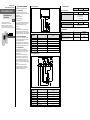
Anschlussbelegung Sender
Pin
M12×8
Signalbezeichnung
Pin
intern
1
NC
–
2
24 V DC
1/2
3
NC
–
4
NC
–
5
NC
–
6
NC
–
7
Masse 0 V
3
8
Funktionserde (FE)
FE
Anschlussbelegung Empfänger
Pin
M12×8
Signalbezeichnung
Pin
intern
1
K13
4
2
24 V DC
1/2
3
K23
9
4
NC
–
5
K14
5
6
K24
8
7
Masse 0 V
3
8
Funktionserde (FE)
FE
9 Technische Daten
Minimal
Typisch
Maximal
Allgemeine Systemdaten
Betriebsreichweite
15 m
70 m
B
10D
-Wert
DC-13 mit 24 V/0,6 A:
1×10
6
Schaltspiele
DC-13 mit 24 V/1,5 A:
2×10
5
Schaltspiele
Empfangseinheit
Schaltspannung
10 V DC
30 V DC
Referenzlasten nach Gebrauchskategorie
DC-1 mit 24 V/1,5 A
DC-13 mit 24 V/1,5 A
10.1 Bestelldaten
Artikel Typ Artikelnummer
Einstrahl-Sicherheits-Lichtschranke:
Sendeeinheit
WSU26/3-103A00S01
1089126
Einstrahl-Sicherheits-Lichtschranke:
Empfangseinheit, Reichweite 15 … 70 m
WEU26/3-203A00S01
1089127

ADDENDUM OPERATING
INSTRUCTIONS
WSU/WEU26-3-S01
Single-beam photoelectric
safety switch
en
SICK AG • Erwin-Sick-Straße 1
D-79183 Waldkirch • www.sick.com
8021807/17LP/2020-04-08 • 2M/TD
Printed in Germany (2020-04)
• All rights
reserved • Subject to change without notice
1 About this document
This document is an original document.
1.3 Scope
This addendum provides information on the
properties of the following single-beam
photoelectric safety switches:
WSU26/3-103A00S01
WEU26/3-203A00S01
This addendum only applies …
only for the single-beam photoelectric safety
switch WSU/WEU26-3 with the following entry
on the type label in the field Operating
Instructions:
8021807
8021807/17LP
only in conjunction with the underlying operating
instructions „WSU/WEU26-3 Single-beam
photoelectric safety switch“ in all available
languages, SICK part number 8013336/YTA4.
3.1 Special features
Contrary to the information in the underlying
operating instructions, the following product
features apply:
M12×8 male connector at sender and receiver.
The receiver WEU26/3-203A00S01 has an
operating range of 15 to 70 m.
5.2 System connection
The floating relay contacts on the receiver
(normally closed and normally open contacts)
are allowed to be operated with a switching
voltage of maximum 30 V DC.
Due to the wire cross-section (0.25 mm²), both
the switching current and supply current must
be limited to maximum 1.5 A.
For the trouble-free operation of the device, a
functional earth (FE) must be connected (it is
not allowed to connect a protective earth (PE)).
If a safety relay (e.g. UE43) is used for cross-
circuit monitoring on the connecting cables, a
functional earth (FE) must also be connected.
Pin assignment sender
Pin
M12×8
Signal designation Pin
internal
1
NC
–
2
24 V DC
1/2
3
NC
–
4
NC
–
5
NC
–
6
NC
–
7
Ground 0 V
3
8
Functional earth (FE)
FE
Pin assignment receiver
Pin
M12×8
Signal designation
Pin
internal
1
K13
4
2
24 V DC
1/2
3
K23
9
4
NC
–
5
K14
5
6
K24
8
7
Ground 0 V
3
8
Functional earth (FE)
FE
9 Technical data
Minimum
Typical
Maximum
General system data
Operating range
15 m
70 m
B
10D
value
DC-13 with 24 V/0.6 A:
1×10
6
switching operations
DC-13 with 24 V/1.5 A:
2×10
5
switching operations
Receiver unit
Switching voltage
10 V DC
30 V DC
Reference loads by usage category
DC-1 with 24 V/1.5 A
DC-13 with 24 V/1.5 A
10.1 Ordering information
Part Type Part number
Single-beam photoelectric safety switch:
Sender unit
WSU26/3-103A00S01
1089126
Single-beam photoelectric safety switch:
Receiver unit, scanning range 15 … 70 m
WEU26/3-203A00S01
1089127
-
 1
1
-
 2
2


in anderen Sprachen
Verwandte Artikel
-
SICK WEU/WSU 26-3-S01 Bedienungsanleitung
-
-
-
-
-
-
-
-
-