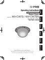
i-PRO i-PRO WV-CW7S Dome Cover ClearSight Coating Benutzerhandbuch
- Typ
- Benutzerhandbuch

Before attempting to connect or install this product,
please read these instructions carefully and save this manual for future use.
The model number is abbreviated in some descriptions in this manual.
Operating Instructions
Included Installation Instructions
Dome Cover
Model No.
WV-CW7S / WV-CW7SN
FRANÇAIS DEUTSCH ENGLISHESPAÑOLITALIANO
РУССКИЙ
ClearSight coating
(Rain wash coating)

2
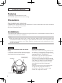
Features
This product is the smoked dome cover.
WV-CW7SN is applied with rain wash coating.
Precautions
Refer installation work to the dealer.
Installation work requires technique and experiences. Failure to observe this may cause fi re, electric
shock, injury, or damage to the product.
Be sure to consult the dealer.
Installations
The following are installation instructions using WV-S2531LN as a representative example. Refer to
manuals of each model upon installation.
Note:
• When the smoke type dome cover is used, the reach distance of IR will become shorter and
the ambient illuminance for the day & night switchover will become lower compared to the
standard clear type dome cover. Please reconfirm the performance after reinstalling the enclo-
sure to the camera.
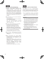
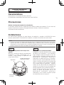
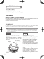
Step 1
Remove the enclosure from the camera
body
Loosen the 4 enclosure fixing screws using the
bit provided with the camera, and then remove
the enclosure from the camera body.
Step 2
Remove the dome cover
Remove the 3 dome cover fixing screws (2 with-
out washers, 1 with washer), and then remove
the dome cover holding plate, the light-blocking
sheet (WV-SFV631LT/ WV-SFV631L/
WV-SFV611L only), the dome cover and the
waterproof rubber from the enclosure.
(The Dome cover holding plate and the camera
body are connected with the installation auxiliary
wire. Please pay attention that the installation
auxiliary wire will be removed at the moment
when the dome cover fixing screws are
removed.)
Keep the removed dome cover holding plate,
the light-blocking sheet (WV-SFV631LT/
WV-SFV631L/ WV-SFV611L only), 3 fixing
screws until using them in step 3.
ENGLISH VERSION
Enclosure
Enclosure fixing
screws (4 pcs.)
Camera body

3
ENGLISH
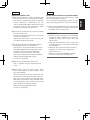
Step 3
Replace the dome cover
AAttach the waterproof rubber provided with
the new dome cover to the enclosure. Make
sure that the waterproof rubber is attached
without distortion or deformation. Do not
use the waterproof rubber removed from the
enclosure. Use the new waterproof rubber
provided with the new dome cover.
BRemove the protection film covering outside
the new dome cover.
Keep the removed protection film until using
it upon the installation.
(Handle the new dome cover with care not
to scratch inside and outside.)
CFit the new dome cover, the light-blocking
sheet (WV-SFV631LT/ WV-SFV631L/
WV-SFV611L only) and the dome cover hol-
ding plate together while aligning the holes
on them to the 2 protrusions inside the
enclosure, and then fix them using the 2
dome cover fixing screws (without washers).
(Recommended tightening torque:
0.78 N·m {0.58 lbf·ft})
DAttach the protection film removed in
stepŰ3Ű-ŰB back to the outside the dome
cover.
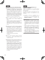
EWhen fixing the third dome cover fixing
screw (with washer), fix the installation auxi-
liary wire together.
When fixing with the screw, make sure that
the flat face of the fixing terminal is the sur-
face side of the dome cover holding plate.
Make also sure that the fixing terminal is not
on the projection of the dome cover holding
plate. (Refer to the diagram below.)
(Recommended tightening torque:
0.78 N·m {0.58 lbf·ft})
Step 4
Fit the enclosure back to the camera body
Fix the enclosure onto the camera body using
the 4 enclosure fixing screws.
The recommended tightening torque for the
enclosure fixing screws is 0.78 N·m {0.58Űlbf·ft}.
Refer to the Installation Guide of the camera
for the subsequent procedures including the
installation of the camera body.
IMPORTANT:
• Defocus may be caused by the reinstalled
enclosure. After installing the enclosure,
activate the auto focus function from the
setup menu.
• Remove the protection film covering the
outside of the dome cover after completing
the installation.
• Wipe out with a soft cloth when cleaning
adhesion of dirt such as a fingerprint.
(WV-CW7S only)
• Refer to "Precautions"(leaflet) and clean
the dome cover. (WV-CW7SN only)

4
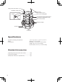
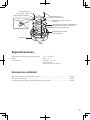
Specifications
Ambient operating temperature: –45 °C to +60 °C {–49 °F to 140 °F}
Mass: Approx. 74 g {0.16 lbs}
Dimensions: Diameter: 115 mm {4-17/32 inches}
Height: 60 mm {2-3/8 inches}
Dome radius 42 mm {1-21/32 inches}
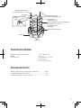
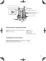
Standard Accessories
Operating Instructions (this document) .............1 set
Precautions (leaflet) ..........................................1 pc
Waterproof rubber (for replacement) ................1 pc.
Fixing screw
(without washer, 2 pcs.)
Installation auxiliary wire
Fixing screw (with washer, 1 pc.)
Dome cover holding plate
Light-blocking sheet (WV-SFV631LT/
WV-SFV631L/ WV-SFV611L only)
Dome cover (smoke)
Waterproof rubber
Protrusion
Enclosure
Washer

5
DEUTSCH
DEUTSCHE AUSGABE
(GERMAN VERSION)
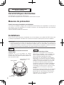
Merkmale
Dieses Produkt stellt die Rauchglas-Glockenabdeckung dar.
Die WV-CW7SN wird mit wasserabstoßender Beschichtung eingesetzt.
Vorsichtsmaßregeln
Zur Installation an einen Fachhändler wenden.
Installationsarbeiten erfordern Fachkenntnisse und Erfahrung. Andernfalls besteht die Gefahr von
Brand, elektrischem Schlag, Verletzungen oder Schäden an diesem Produkt.
Unbedingt einen Fachhändler konsultieren.
Installation
Im Folgenden wird das Installationsverfahren anhand des Modells WV-S2531LN beschrieben. Bei
der Installation auf das Handbuch des jeweiligen Modells beziehen.
Anmerkung:
• Bei Verwendung der Rauchglas-Glocke verkürzt sich die IR-Reichweite und die Beleuchtungs-
stärke im Umfeld für die Tag/Nacht-Umschaltung wird schwächer im Vergleich zur Klarsicht-
Glocke. Die Funktion der Kamera nach dem Einbau in das Gehäuse nochmals überprüfen.
Schritt 1
Das Gehäuse von der Kamerakörper
abnehmen
Die 4 Gehäuse-Befestigungsschrauben mit
dem der Kamera beiliegenden Einsatz lösen
und anschließend das Gehäuse vom Kamera-
körper trennen.
Schritt 2
Entfernen der Glockenabdeckung
Die 3 Befestigungsschrauben der Glockenab-
deckung (2 ohne und 1 mit Unterlegscheibe)
herausdrehen und die Halteplatte, den lichtblo-
ckierenden Ring (nur WV-SFV631LT/
WV-SFV631L/ WV-SFV611L), die
Glockenabdeckung und den wasserdichten
Gummiring vom Gehäuse abnehmen.
(Die Halteplatte der Glockenabdeckung und
der Kamerakörper sind durch einen Fangdraht
verbunden. Dieser Fangdraht muss beim
Herausdrehen der Befestigungsschrauben der
Glockenabdeckung ebenfalls gelöst werden.)
Die Halteplatte der Glockenabdeckung, den
lichtblockierenden Ring (nur WV-SFV631LT/
WV-SFV631L/ WV-SFV611L) und die 3
Befestigungs schrauben zur Wiederverwendung
in Schritt 3 aufbewahren.
Gehäuse
Gehäuse-Befestigungs-
schrauben (4 St.)
Kamerakörper

6
Schritt 3
Anbringen der Glockenabdeckung
ADen der neuen Glockenabdeckung beilie-
genden wasserdichten Gummiring am
Gehäuse anbringen. Darauf achten, den
wasserdichten Gummiring beim Einbau nicht
zu verdrehen oder verformen. Der alte was-
serdichte Gummiring, der vom Gehäuse ent-
fernt wurde, darf nicht wiederverwendet
werden. Den der neuen Glockenabdeckung
beiliegenden wasserdichten Gummiring ver-
wenden.
BDie Schutzfolie von der neuen Glockenab-
deckung abziehen.
Die abgezogene Schutzfolie für die Wieder-
verwendung aufbewahren.
(Die neue Glockenabdeckung vorsichtig
behandeln, damit sie weder innen noch
außen verkratzt wird.)
CDie neue Glockenabdeckung, den lichtblo-
ckierenden Ring (nur WV-SFV631LT/
WV-SFV631L/ WV-SFV611L) und die
Halteplatte zusammenfügen, die darin
befindlichen Löcher auf 2 der Haltenasen im
Inneren des Gehäuses ausrichten und die
Teile dann mit 2 der Befestigungsschrauben
(ohne Unterlegscheiben) verschrauben.
(Empfohlenes Anzugsmoment: 0,78 N·m)
DDie in Schritt 3 - B abgezogene Schutzfolie
wieder außen an der Glockenabdeckung
anbringen.
EBeim Einschrauben der dritten Befesti-
gungsschraube der Glockenabdeckung (mit
Unterlegscheibe) den Fangdraht mit der
Schraube sichern.
Dabei darauf achten, dass die Öse am
Fangdraht mit der flachen Seite auf dem
Halteplatte aufliegt. Sicherstellen, das die
Öse am Fangdraht nicht auf einem
Vorsprung der Halteplatte aufliegt. (Siehe
die folgende Abbildung.)
(Empfohlenes Anzugsmoment: 0,78 N·m)
Schritt 4
Das Gehäuse wieder am Kamerakörper
anbringen
Das Gehäuse mit den 4 Gehäuse-Befesti-
gungsschrauben am Kamerakörper befestigen.
Für die Gehäuse-Befestigungsschrauben wird
ein Anzugsmoment von 0,78 N·m empfohlen.
Die anschließenden Schritte einschließlich
der Installation des Kamerakörpers sind im
Installationshandbuch der Kamera beschrie-
ben.
WICHTIG:
• Durch das Wiederanbringen des Gehäuses
kann die Fokuseinstellung gestört werden.
Nach Anbringen des Gehäuses die Fokus-
Automatik über das Setupmenü aktivieren.
• Nachdem die Installation beendet ist, die
Schutzfolie von der Außenfläche der
Glockenabdeckung entfernen.
• Anhaftenden Schmutz oder
Fingerabdrücke mit einem weichen Lappen
abwischen. (nur WV-CW7S)
• Zum Reinigen der Glockenabdeckung
siehe “Vorsichtsmaßregeln” (Broschüre).
(nur WV-CW7SN)

7
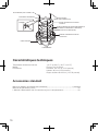
Befestigungsschraube
(ohne Unterlegscheibe, 2 St.)
Fangdraht
Befestigungsschraube
(mit Unterlegscheibe, 1 St.)
Halteplatte der
Glockenabdeckung
Lichtblockierender Ring (nur WV-SFV631LT/
WV-SFV631L/ WV-SFV611L)
Glockenabdeckung
(Rauchglas)
Wasserdichter Gummiring
Haltenase
Gehäuse
Unterleg-
scheibe
Technische Daten
Betriebsumgebungstemperatur: –45 °C bis +60 °C
Masse: Ca. 74 g
Abmessungen: Durchmesser: 115 mm
Höhe: 60 mm
Dome-Radius 42 mm
Standardzubehör
Bedienungsanleitung (vorliegendes Dokument) ..............1 Satz
Vorsichtsmaßregeln (Broschüre) ....................................... 1 St.
Wasserdichter Gummiring (Ersatzteil) ............................... 1 St.

8
Caractéristiques dominantes
Ce produit est le couvercle en dôme fumé.
WV-CW7SN est appliqué avec le revêtement d’élimination de pluie.
Mesures de précaution
Confier les travaux d’installation au distributeur.
Les travaux d’installation exigent des connaissances techniques et de l’expérience. Le fait de ne
pas observer ceci peut engendrer un incendie, provoquer une décharge électrique, des blessures
voire endommager ce produit.
Faire en sorte de consulter le distributeur.
Installations
Ce qui suit sont les instructions d’installation lors d’une utilisation du modèle WV-S2531LN en tant
qu’exemple représentatif. Se référer aux manuels de chaque modèle après avoir fait l’installation.
Remarque:
• Quand le couvercle en dôme de type fumé est utilisé, la distance de portée de la lumière infra-
rouge deviendra plus courte et l’éclairement ambiant pour la commutation diurne/nocturne
deviendra plus faible comparée au couvercle en dôme de type transparent. Veuillez reconfirmer
les performances après la réinstallation du coffret extérieur de la caméra vidéo.
Étape 1
Retirer le coffret extérieur du bloc de
caméra vidéo
Desserrer les 4 vis de fixation du coffret
extérieur en utilisant le foret fourni avec cette
caméra vidéo, puis retirer le coffret extérieur du
bloc de caméra vidéo.
Coffret extérieur
Vis de fixation de coffret
extérieur (4 él.)
Bloc de
caméra vidéo
VERSION FRANÇAISE
(FRENCH VERSION)
Étape 2
Retirer le couvercle en dôme
Retirer les 3 vis de fixation du couvercle en
dôme (2 sans rondelles, 1 avec rondelle), puis
retirer la plaque de fixation de couvercle en
dôme, la feuille de blocage de lumière
(WV-SFV631LT/ WV-SFV631L/ WV-SFV611L
seulement), le couvercle en dôme et l’élément
d'étanchéité à l'eau en caoutchouc du coffret
extérieur. (La plaque de fixation de couvercle
en dôme et le bloc de camera vidéo sont
connectés à l'aide du fil auxiliaire d’installation.
Veuillez faire attention à ce que le fil auxiliaire
d’installation soit bien retiré au moment où les
vis de fixation du couvercle en dôme sont
retirées.)
Conserver la plaque de fixation de couvercle en
dôme retirée, la feuille de blocage de lumière
(WV-SFV631LT/ WV-SFV631L/ WV-SFV611L
seulement), les 3 vis de fixation jusqu’à les
utiliser au cours de l’étape 3.

9
Étape 3
Remplacer le couvercle en dôme
AFixer l’élément d’étanchéité à l’eau en caou-
tchouc fourni avec le couvercle en dôme
neuf sur le coffret extérieur. S’assurer que
l’élément d’étanchéité à l’eau en caou-
tchouc est fixé sans présenter de distortion
ni de déformation. Ne pas réutiliser l’élément
d’étanchéité à l’eau en caoutchouc qui a été
retiré du coffret extérieur. Utiliser l’élément
d’étanchéité à l’eau en caoutchouc neuf
fourni avec le couvercle en dôme neuf.
BRetirer le film de protection recouvrant la
surface extérieure du couvercle en dôme
neuf.
Conserver le film de protection retiré jusqu’à
l’utiliser après avoir effectué l’installation.
(Manipuler le couvercle en dôme neuf avec
soin afin de ne pas rayer les surfaces inté-
rieure et extérieure.)
CInstaller le couvercle en dôme neuf, la feuille
de blocage de lumière (WV-SFV631LT/
WV-SFV631L/ WV-SFV611L seulement) et
la plaque de fixation de couvercle en dôme
en les assemblant et tout en alignant leurs
trous percés avec les 2 parties saillantes à
l’intérieur du coffret extérieur, puis les fixer
en utilisant les 2 vis de fixation de couvercle
en dôme (sans rondelles).
(Couple de serrage recommandé:
0,78 N·m {0,58 lbf·ft})
DRemettre en place le film de protection retiré
au cours de l’étape 3 - B sur la surface
extérieure du couvercle en dôme.
EAu moment de fixer la troisième vis de fixa-
tion du couvercle en dôme (avec rondelle),
fixer le fil auxiliaire d'installation en même
temps.
Au moment d’effectuer la fixation avec la vis,
s’assurer que la face plane de la borne de
fixation est le côté extérieur de la plaque de
fixation du couvercle en dôme. S’assurer
également que la borne de fixation n’est pas
sur la partie saillante de la plaque de fixation
du couvercle en dôme. (Se référer au
schéma ci-dessous.)
(Couple de serrage recommandé:
0,78 N·m {0,58 lbf·ft})
Étape 4
Remonter le coffret extérieur sur le bloc
de caméra vidéo
Fixer le coffret extérieur sur le bloc de caméra
vidéo en utilisant les 4 vis de fixation de coffret
extérieur.
Le couple de serrage recommandé pour les vis
de fixation de coffret extérieur est 0,78 N·m
{0,58 lbf·ft}.
Se référer au guide d’installation de la
caméra vidéo en ce qui concerne les procé-
dures suivantes comprenant l’installation du
bloc de caméra vidéo.
IMPORTANT:
• Un flou d’image risque d’être provoqué par
la réinstallation du coffret extérieur. Une
fois le coffret extérieur installé, exécuter la
fonction de mise au point automatique à
partir du menu de configuration.
• Retirer le film de protection recouvrant la
surface extérieure du couvercle en dôme
une fois l’installation terminée.
• Essuyer avec un morceau de tissu souple
pour nettoyer les saletés qui ont adhérées
telle qu’une empreinte digitale. (WV-CW7S
seulement)
• Se référer à la rubrique "Mesures de pré-
caution" (notice) et nettoyer le couvercle en
dôme. (WV-CW7SN seulement)
FRANÇAIS

10
Caractéristiques techniques
Température ambiante en service: –45 °C à +60 °C {–49 °F a 122 °F}
Masse: Environ 74 g {0,16 lbs}
Dimensions: Diamètre: 115 mm {4-17/32 pouces}
Hauteur: 60 mm {2-3/8 pouces }
Rayon de dôme de 42 mm {1-21/32 pouces}
Accessoires standard
Manuel d’utilisation (la présente documentation) ...................................................1 ensemble
Mesures de précaution (notice) ........................................................................................1 él.
L’élément d’étanchéité à l’eau en caoutchouc (pour le remplacement) ..............................1 él.
Vis de fixation
(sans rondelle, 2 él.)
Fil auxiliaire d’installation
Vis de fixation (avec rondelle, 1 él.)
Plaque de fixation de couvercle
en dôme
Feuille de blocage de lumière (WV-SFV631LT/
WV-SFV631L/ WV-SFV611L seulement)
Couvercle en dôme (fumé)
Élément d’étanchéité à l’eau en
caoutchouc
Partie saillante
Coffret extérieur
Rondelle

11
Características
Este producto es la cubierta de domo ahumada.
Se ha aplicado revestimiento contra la lluvia a la WV-CW7SN.
Precauciones
Solicite el trabajo de instalación al distribuidor.
Es necesario poseer técnica y experiencia para realizar el trabajo de instalación. Si no lo hace así,
pueden ocasionarse incendios, descargas eléctricas, heridas, o daños en el producto.
Consúltelo sin falta al distribuidor.
Instalaciones
Las instrucciones siguientes son para efectuar la instalación y emplean la WV-S2531LN como
ejemplo representativo. Para efectuar la instalación, consulte los manuales de cada modelo.
Nota:
• Cuando se emplea la cubierta ahumada del domo, la distancia de alcance de los rayos infrar-
rojos es más corta y la iluminación ambiental para el cambio de día y noche es más baja en
comparación con la utilización de la cubierta transparente del domo. Vuelva a confirmar el ren-
dimiento después de haber reinstalado el alojamiento en la cámara.
Paso 1
Extraiga el alojamiento del cuerpo de la
cámara
Afloje los 4 tornillos de fijación del alojamiento
empleando la broca suministrada con la
cámara, y luego extraiga el alojamiento del
cuerpo de la cámara.
Alojamiento
Tornillos de fijación del
alojamiento (4 piezas)
Cuerpo de
la cámara
VERSION ESPAÑOLA
(SPANISH VERSION)
ESPAÑOL
Paso 2
Extracción de la cubierta del domo
Extraiga los 3 tornillos de fijación de la cubierta
del domo (2 sin arandelas y 1 con arandela) y
luego extraiga la placa de sujeción de la cubi-
erta del domo, la lámina de bloqueo de la luz
(WV-SFV631LT/ WV-SFV631L/ WV-SFV611L
solamente), la cubierta del domo y la empaqu-
etadura de goma impermeabilizante del aloja-
miento. (La placa de sujeción de la cubierta del
domo y el cuerpo de la cámara se conectan
con el cable auxiliar de instalación. Tenga en
cuenta que el cable auxiliar de instalación se
quitará en el momento en que se extraigan los
tornillos de fijación de la cubierta del domo.)
Guarde la placa de sujeción de la cubierta del
domo, la lámina de bloqueo de la luz
(WV-SFV631LT/ WV-SFV631L/ WV-SFV611L
solamente) y los 3 tornillos de fijación porque
los utilizará de nuevo en el paso 3.

12
Paso 3
Reinstalación de de la cubierta del domo
AColoque la empaquetadura de goma imper-
meabilizante, provista con la nueva cubierta
del domo, en el alojamiento. Asegúrese de
que la empaquetadura de goma imperme-
abilizante quede instalada sin distorsión ni
deformación. No emplee la unidad con la
empaquetadura de goma impermeabilizante
extraída del alojamiento. Emplee la empaqu-
etadura de goma impermeabilizante sumin-
istrada con la nueva cubierta del domo.
BQuite la película protectora que cubre la
parte exterior de la nueva cubierta del
domo.
Guarde la película protectora extraída hasta
que se vuelva a usar para la instalación.
(Manipule con cuidado la nueva cubierta del
domo para que no se raye por dentro ni por
fuera.)
CAcople la nueva cubierta del domo, la lámina
de bloqueo de la luz (WV-SFV631LT/
WV-SFV631L/ WV-SFV611L solamente) y la
placa de sujeción de la cubierta del domo
alineando sus orificios con los 2 salientes
que hay dentro del alojamiento y fíjelos con
los 2 tornillos de fijación (sin arandelas) de la
cubierta del domo.
(Torsión de apriete recomendada:
0,78 N·m)
DFije de nuevo la película protectora extraída
en el paso 3 - B a la parte exterior de la
cubierta del domo.
ECuando fije el tercer tornillo de fijación (con
arandela) de la cubierta del domo, fije tam-
bién el cable auxiliar al mismo tiempo.
Cuando efectúe la fijación con el tornillo,
asegúrese de que la superficie plana del ter-
minal de fijación esté en el lado de la super-
ficie de la placa de sujeción de la cubierta
del domo. Asegúrese también de que el ter-
minal de fijación no quede en el saliente de
la placa de sujeción de la cubierta del
domo. (Consulte la ilustración siguiente.)
(Torsión de apriete recomendada:
0,78 N·m)
Paso 4
Acoplamiento del alojamiento en el
cuerpo de la cámara
Acople el alojamiento en el cuerpo de la
cámara empleando los 4 tornillos de fijación
del alojamiento.
La torsión de apriete recomendada para los
tornillos de fijación del alojamiento es de
0,78ŰN·m.
Consulte la Guía de instalación de la
cámara para ver los procedimientos sub-
siguientes incluyendo la instalación del
cuerpo de la cámara.
IMPORTANTE:
• El alojamiento montado puede causar
desenfoque. Después de haber instalado
el alojamiento, active la función de enfoque
automático desde el menú de configura-
ción.
• Quite la película protectora que cubre la
parte exterior de la cubierta del domo
después de haber finalizado la instalación.
• Para sacar la suciedad, como puedan ser
las huellas dactilares, frote con un paño
suave. (WV-CW7S solamente)
• Antes de limpiar la cubierta del domo,
consulte el apartado “Precauciones” (fol-
leto). (WV-CW7SN solamente)

13
Especificaciones
Temperatura ambiental de funcionamiento: –45 °C a +60 °C
Masa: Aprox. 74 g
Dimensiones: Diámetro: 115 mm
Altura: 60 mm
Radio del domo de 42 mm
Accesorios estándar
Manual de instrucciones (este documento) ................................................................ 1 juego
Precauciones (folleto) ................................................................................................. 1 pieza
Empaquetadura de goma impermeabilizante (de recambio) ......................................... 1 pieza
Tornillo de fijación
(sin arandela, 2 piezas)
Cable auxiliar de instalación
Tornillo de fijación
(con arandela, 1 pieza)
Placa de sujeción de la cubierta
del domo
Lámina de bloqueo de la luz (WV-SFV631LT/
WV-SFV631L/ WV-SFV611L solamente)
Cubierta del domo (ahumada)
Empaquetadura de goma
impermeabilizante
Saliente
Alojamiento
Arandela

14
Caratteristiche
Questo prodotto è il coperchio a cupola grigio fumo.
Al WV-CW7SN è applicato il rivestimento antipioggia.
Precauzioni
Rivolgersi al rivenditore per i lavori di installazione.
I lavori di installazione richiedono tecnica ed esperienza. La mancata osservanza di questa pre-
cauzione può causare incendi, scosse elettriche, ferite o danni al prodotto.
Non esitare a rivolgersi al rivenditore.
Installazioni
Le seguenti sono le istruzioni per l’installazione utilizzando la WV-S2531LN come esempio rappre-
sentativo. Far riferimento ai manuali di ciascun modello al momento dell’installazione.
Nota:
• Quando si utilizza il coperchio a cupola grigio fumo, si accorcerà la distanza del raggio di IR e
l’illuminazione dell’ambiente per il passaggio tra giorno e notte si abbasserà in confronto al
coperchio a cupola trasparente standard. Riconfermare le prestazioni dopo aver reinstallato
l’involucro sulla telecamera.
Passaggio 1
Rimuovere l’involucro dal corpo della
telecamera
Allentare le 4 viti di fissaggio dell’involucro uti-
lizzando la punta fornita con la telecamera,
quindi rimuovere l’involucro dal corpo della
teleca mera.
Involucro
Viti di fissaggio
dell’involucro (4 pz.)
Corpo della
telecamera
VERSION ITALIANA
(ITALIAN VERSION)
Passaggio 2
Rimuovere il coperchio a cupola
Rimuovere le 3 viti di fissaggio del coperchio a
cupola (2 senza rondelle, 1 con rondella),
quindi rimuovere la piastra di fissaggio del
coperchio a cupola, il foglio di protezione dalla
luce (Soltanto WV-SFV631LT/ WV-SFV631L/
WV-SFV611L), il coperchio a cupola e la
gomma impermeabile dall’involucro.
(La piastra di fissaggio del coperchio a cupola
e il corpo della telecamera sono collegati con il
cavo ausiliario per l’installazione. Prestare
attenzione poiché il cavo ausiliario per
l’installazione verrà rimosso nel momento in cui
si rimuovono le viti di fissaggio del coperchio a
cupola.)
Conservare la piastra di fissaggio del coperchio
a cupola, il foglio di protezione dalla luce
(Soltanto WV-SFV631LT/ WV-SFV631L/
WV-SFV611L) e le 3 viti di fissaggio rimossi fino
al loro utilizzo nel passaggio 3.

15
Passaggio 3
Sostituire il coperchio a cupola
AFissare all’involucro la gomma impermeabile
fornita con il nuovo coperchio a cupola.
Assicurarsi che la gomma impermeabile sia
fissata senza distorsione o deformazione.
Non utilizzare la gomma impermeabile
rimossa dall’involucro. Utilizzare la nuova
gomma impermeabile fornita con il nuovo
coperchio a cupola.
BRimuovere la pellicola di protezione che
ricopre l’esterno del nuovo coperchio a
cupola.
Conservare la pellicola di protezione fino al
suo utilizzo durante l’installazione.
(Maneggiare con cura il nuovo coperchio a
cupola per non graffiare l’interno e l’esterno.)
CAssemblare il nuovo coperchio a cupola, il
foglio di protezione dalla luce (Soltanto
WV-SFV631LT/ WV-SFV631L/
WV-SFV611L) e la piastra di fissaggio del
coperchio a cupola allineando i rispettivi fori
alle 2 sporgenze all’interno dell’involucro,
quindi fissarli utilizzando le 2 viti di fissaggio
del coperchio a cupola (senza rondelle).
(Coppia di torsione dell’avvitamento consigli-
ata: 0,78 N·m)
DRiattaccare la pellicola di protezione rimossa
nel passaggio 3 - B all’esterno del coper-
chio a cupola.
ENel momento in cui si fissa la terza vite di fis-
saggio del coperchio a cupola (con ron-
della), fissare anche il cavo ausiliario per
l’installazione.
Durante il fissaggio con la vite, assicurarsi
che la superficie piatta del terminale di fis-
saggio sia sulla superficie della piastra di fis-
saggio del coperchio a cupola. Assicurarsi
anche che il terminale di fissaggio non sia
sulla sporgenza della piastra di fissaggio del
coperchio a cupola. (Far riferimento
all’illustrazione seguente.)
(Coppia di torsione dell’avvitamento consigli-
ata: 0,78 N·m)
Passaggio 4
Reinstallare l’involucro sul corpo della
telecamera
Fissare l’involucro sul corpo della telecamera
utilizzando le 4 viti di fissaggio dell’involucro.
La coppia di torsione consigliata per
l’avvitamento delle viti di fissaggio dell’involucro
è 0,78ŰN·m.
Far riferimento alla Guida all’installazione
della telecamera per le successive proce-
dure, compresa l’installazione del corpo
della telecamera.
IMPORTANTE:
• La reinstallazione dell’involucro può cau-
sare una perdita di messa a fuoco. Dopo
l’installazione dell’involucro, attivare la fun-
zione di messa a fuoco automatica dal
menu di configurazione.
• Rimuovere la pellicola di protezione che
ricopre l’esterno del coperchio a cupola
dopo aver completato l’installazione.
• Strofinare con un panno morbido per pulire
lo sporco residuo come eventuali impronte.
(Soltanto WV-CW7S)
• Far riferimento a "Precauzioni" (opuscolo) e
pulire il coperchio a cupola. (Soltanto
WV-CW7SN)
ITALIANO

16
Dati tecnici
Temperatura ambiente di funzionamento: Da –45 °C a +60 °C
Massa: Circa 74 g
Dimensioni: Diametro: 115 mm
Altezza: 60 mm
Raggio della cupola 42 mm
Accessori standard
Manuale di istruzioni (questo documento) ...................... 1 set
Precauzioni (opuscolo) ................................................... 1 pz.
Gomma impermeabile (di ricambio) ..................................1 pz.
Vite di fissaggio
(senza rondella, 2 pz.)
Cavo ausiliario per l’installazione
Vite di fissaggio
(con rondella, 1 pz.)
Piastra di fissaggio del
coperchio a cupola
Foglio di protezione dalla luce (Soltanto
WV-SFV631LT/ WV-SFV631L/ WV-SFV611L)
Coperchio a cupola
(grigio fumo)
Gomma impermeabile
Sporgenza
Involucro
Rondella

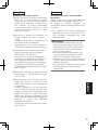
17
РУССКАЯ ВEРСИЯ
(RUSSIAN VERSION)
РУССКИЙ
Характеристики
Данное изделие представляет собой крышку купола дымчатого типа.
На WV-CW7SN нанесено водоотталкивающее покрытие.
Меры предосторожности
Монтажные работы следует поручить дилеру.
Монтажные работы требуют технических навыков и опыта. Несоблюдение этого
требования может привести к пожару, поражению электрическим током, травмам или
повреждению изделия.
Нужно обязательно обращаться к дилеру.
Монтаж
Ниже приведены инструкции по установке, используя WV-S2531LN в качестве образца.
См. руководства по установке каждой модели.
Замечание:
• При использовании дымчатой крышки купола радиус действия ИК сенсора станет
короче, а освещенность окружающей обстановки для смены дня и ночи станет ниже по
сравнению со стандартной прозрачной крышкой купола. Пожалуйста, убедитесь в
исправной работе после возврата крышки на камеру.
Шаг 1
Снимите корпус с корпуса камеры
Ослабьте 4 крепежных винта корпуса с
помощью долота, поставляемого с
камерой, а затем снимите корпус с корпуса
камеры.
Корпус
Крепежные винты
корпуса (4 шт.)
Корпус
камеры
Шаг 2
Снимите крышку купола
Снимите 3 фиксирующих винта крышки
купола (2 без шайб, 1 с шайбой), после
чего снимите удерживающую пластину
крышки купола, светозащитный лист
(Только WV-SFV631LT/ WV-SFV631L/
WV-SFV611L), крышку купола и
водонепроницаемую резиновую прокладку
из корпуса.
(Удерживающая пластина крышки купола и
корпус камеры подключены при помощи
установки вспомогательного провода.
Обратите внимание, установки
вспомогательного провода будет удален в
тот момент, когда будут сняты
фиксирующие винты крышки купола.)
Храните снятую удерживающую пластину
крышки купола, светозащитный лист
(Только WV-SFV631LT/ WV-SFV631L/
WV-SFV611L), 3 фиксирующих винта до их
использования в шаге 3.

18
Шаг 3
Поставьте обратно крышку купола
AПрисоедините водонепроницаемую
резину, поставляемую с новой крышкой
купола, к корпусу. Убедитесь, что
водонепроницаемая резина
прикреплена без искривлений или
деформаций. Не используйте
водонепроницаемую резину, снятую с
корпуса. Используйте новую
водонепроницаемую резину,
поставляемую с новой крышкой купола.
BСнимите защитную пленку с внешней
стороны новой крышки купола.
Храните снятую защитную пленку до
использования после установки.
(Обращайтесь осторожно с новой
крышкой купола, чтобы не поцарапать
ее внутри и снаружи.)
CУстановите новую крышку купола,
светозащитный лист (Только
WV-SFV631LT/ WV-SFV631L/
WV-SFV611L) и удерживающую
пластину крышки купола вместе,
совместив их отверстия с 2 выступами
внутри корпуса, а затем закрепите их с
помощью 2 фиксирующих винтов
крышки купола (без шайб).
(Рекомендуемый крутящий момент при
затяжке винтов:
0,78 N·m)
DУстановите защитную пленку, снятую в
шаге 3 - B, обратно на внешнюю
крышку купола.
EПри установке третьего фиксирующих
винт крышки купола (с шайбой),
закрепите одно- временно установки
вспомогательного провода.
При закреплении с помощью винта,
убедитесь в том, что плоская
поверхность крепежного разъема
является боковой поверхностью
удерживающей пластины крышки
купола. Также убедитесь, что крепежный
разъем не выступает за удерживающую
пластину крышки купола. (См.
диаграмму ниже.)
(Рекомендуемый крутящий момент при
затяжке винтов:
0,78 N·m)
Шаг 4
Установите корпус обратно на корпус
камеры
Закрепите корпус на корпусе камеры,
используя 4 крепежных винта корпуса.
Рекомендуемый момент затяжки для
крепежных винтов корпуса 0,78 N·m.
См. Руководство по монтажу камеры
для последующих процедур, включая
установку корпуса камеры.
ВНИМАНИЕ:
• Переустановка корпуса может вызвать
расфокусировку. После установки
корпуса, активируйте функцию
автоматической фокусировки в меню
настройки.
• Снимите защитную пленку с внешней
стороны крышки купола после
завершения установки.
• Протрите его мягкой тканью при очистке
прилипшего загрязнения, такого как отпечатки
пальцев. (Только WV-CW7S)
• См. раздел “Меры предосторожности”
(брошюра) и проведите чистку крышки
куполообразной головки. (Только WV-CW7SN)

19
Фиксирующих винт
(без шайбы, 2 шт.)
Установка вспомогательного провода
Фиксирующих винт (с шайбой, 1 шт.)
Удерживающая пластина крышки
купола
Светозащитный лист (Только
WV-SFV631LT/ WV-SFV631L/ WV-SFV611L)
Крышка купола (затемненная)
Водонепроницаемая резина
Выступ
Корпус
Шайба
Технические характеристики
Температура окружающей среды при эксплуатации: –45 °C до +60 °C
Масса: Около 74 g
Габаритные размеры: Диаметр: 115 mm
Высота: 60 mm
Купольный радиус 42 mm
Стандартные аксессуары
Инструкция по эксплуатации (настоящий документ) ..1 комплект.
Меры предосторожности (брошюра) ...................................... 1 шт.
Водонепроницаемая резина (для замены) ............................ 1 шт.

[Русский язык]
Декларация о Соответствии Требованиям Технического Регламента об Ограничении
Использования некоторых Вредных Веществ в электрическом и электронном
оборудовании (утверждённого Постановлением №1057 Кабинета Министров
Украины)
Изделие соответствует требованиям Технического Регламента об Ограничении
Использования некоторых Вредных Веществ в электрическом и электронном
оборудовании (ТР ОИВВ).
Содержание вредных веществ в случаях, не предусмотренных Дополнением №2 ТР
ОИВВ:
1. свинец (Pb) – не превышает 0,1 % веса вещества или в концентрации до 1000 миллионных частей;
2. кадмий (Cd) – не превышает 0,01 % веса вещества или в концентрации до 100 миллионных частей;
3. ртуть (Hg) – не превышает 0,1 % веса вещества или в концентрации до 1000 миллионных частей;
4. шестивалентный хром (Cr6+) – не превышает 0,1 % веса вещества или в концентрации
до 1000 миллионных частей;
5. полибромбифенолы (PBB) – не превышает 0,1 % веса вещества или в концентрации до
1000 миллионных частей;
6. полибромдифеноловые эфиры (PBDE) – не превышает 0,1 % веса вещества или в
концентрации до 1000 миллионных частей.
[Українська мова]
Декларація про Відповідність Вимогам Технічного Регламенту Обмеження
Використання деяких Небезпечних Речовин в електричному та електронному облад-
нанні (затвердженого Постановою №1057 Кабінету Міністрів України)
Виріб відповідає вимогам Технічного Регламенту Обмеження Використання деяких
Небезпечних Речовин в електричному та електронному обладнанні (ТР ОВНР).
Вміст небезпечних речовин у випадках, не обумовлених в Додатку №2 ТР ОВНР, :
1. свинець(Pb) – не перевищує 0,1 % ваги речовини або в концентрації до 1000 частин на мільйон;
2. кадмій (Cd) – не перевищує 0,01 % ваги речовини або в концентрації до 100 частин на мільйон;
3. ртуть(Hg) – не перевищує 0,1 % ваги речовини або в концентрації до 1000 частин на мільйон;
4. шестивалентний хром (Cr6+) – не перевищує 0,1 % ваги речовини або в концентрації до
1000 частин на мільйон;
5. полібромбіфеноли (PBB) – не перевищує 0,1 % ваги речовини або в концентрації до
1000 частин на мільйон;
6. полібромдефенілові ефіри (PBDE) – не перевищує 0,1 % ваги речовини або в
концентрації до 1000 частин на мільйон.
For U.S. and Canada:
i-PRO Americas Inc.
For Europe and other countries:
i-PRO EMEA B.V.
https://www.i-pro.com/
Printed in China
Gedruckt in China
Imprimé en Chine
Impreso en China
Stampato in Cina
© i-PRO Co., Ltd. 2022 Ns1116-3042 PGQX2146WA Напечатано в Китае
-
 1
1
-
 2
2
-
 3
3
-
 4
4
-
 5
5
-
 6
6
-
 7
7
-
 8
8
-
 9
9
-
 10
10
-
 11
11
-
 12
12
-
 13
13
-
 14
14
-
 15
15
-
 16
16
-
 17
17
-
 18
18
-
 19
19
-
 20
20


i-PRO i-PRO WV-CW7S Dome Cover ClearSight Coating Benutzerhandbuch
- Typ
- Benutzerhandbuch
in anderen Sprachen
Verwandte Artikel
Andere Dokumente
-
Avigilon 8.0MP-HD-DOME-180 Installationsanleitung
-
 American Dynamics illustra 610 Schnellstartanleitung
-
Samsung SCC-931TP Benutzerhandbuch
-
Axis Q6032-E PTZ Installationsanleitung
-
Axis Communications Q6042 Benutzerhandbuch
-
Axis Communications T95A10 Benutzerhandbuch
-
-
Axis Communications P5512 PTZ Installationsanleitung
-
Monster Oron Gaming Chair Bedienungsanleitung
