
LED lichtsignaalamatuur
De inbouw en montage van elektrische apparaten
mag alleen door een elektromonteur worden uitge-
voerd.
Als de handleiding niet wordt opgevolgd, kunnen
schade aan het apparaat, brand of andere gevaren
ontstaan.
Deze handleiding is onderdeel van het product en
moet door de eindklant worden bewaard.
Functie
Bedoeld gebruik
• Led lichtsignaal, toe te passen met voedingseen-
heid SV 539 … LED
Producteigenschappen
• ter oriëntatie, verlichting en aanduiden van
obstakels
LED pilot lights
Electrical equipment may only be installed and tted
by electrically skilled persons.
Failure to observe the instructions may cause dama-
ge to the device and result in re and other hazards.
These instructions are an integral part of the pro-
duct, and must remain with the end customer.
Function
Intended use
• LED pilot lights for the use with power supply insert
SV539..LED
Product characteristics
• for orientation, illumination and status indication
LED-Lichtsignale
Einbau und Montage elektrischer Geräte dürfen nur
durch Elektrofachkräfte erfolgen.
Bei Nichtbeachten der Anleitung können Schäden
am Gerät, Brand oder andere Gefahren entstehen.
Diese Anleitung ist Bestandteil des Produktes und
muss beim Endkunden verbleiben.
Funktion
Bestimmungsgemäßer Gebrauch
• LED-Lichtsignale zur Verwendung mit Spannungs-
versorgung SV539..LED
Produkteigenschaften
• zur Orientierung, Beleuchtung und Anzeigen von
Zuständen
ALBRECHT JUNG GMBH & CO.KG
Volmestraße 1
58579 Schalksmühle
Germany
Telefon: +49.2355.8060
Telefax: +49.2355.806240
www.jung.de
Service-Center
Kupferstraße 17-19
44532 Lünen
Germany
LED-Lichtsignale
Art.-Nr.: ..539..LED..
0024095403 10.2014
2
1
Abb. 1
Abb. 2
Abb. 3
Abb. 4
Abb. 6
Abb. 7
Abb. 5
D
GB
NL
D
GB
NL

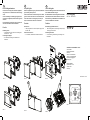
Information für Elektrofachkräfte
Montage und elektrischer Anschluss
LED-Lichtsignal mit Rahmen auf den Einsatz stecken.
Die elektrische Kontaktierung erfolgt über den Stecker (1).
Abb. 1: Montage LED-Orientierungslicht
Abb. 2: Montage LED-Leselicht
Abb. 3: Montage LED-Lichtsignal Hinweis
Abb. 4: Öffnen LED-Lichtsignal Hinweis
Abb. 5: Montage LED-Lichtsignal
Abb. 6: Öffnen LED-Lichtsignal
Abb. 7: Kontaktierung und DIP-Schalter
Anschluss
Anschluss an L, L‘ und N bzw. F1, F2 und ⊥ der
Spannungsversorgung. (Anschluss siehe Abb. 8ab, 9ab)
i Der Spannungsversorgungs-Einsatz ist nicht dimm-
bar.
LED-Lichtsignal mit RGB-LEDs
Mit dem 3-poligen DIP-Schalter (Abb.7, 2) auf der
Rückseite sind verschiedene Farben einstellbar
(Anschluss siehe Abb. 8a, 9a):
1 0 0 = rot 0 1 0 = blau
0 0 1 = grün 1 1 0 = violett
1 0 1 = gelb 0 1 1 = hellblau
1 1 1 = weiß
Eine „Ampelfunktion“ ist in der Schalterstellung 1 0 1
möglich (Anschluss siehe Abb. 8b, 9b):
▪ nur L‘ bzw. F2 bestromt: rot
▪ L und L‘ bzw. F1 und F2 bestromt: gelb
▪ nur L bzw. F1 bestromt: grün
LED-Lichtsignal mit weißen oder blauen LEDs
▪ L und N bzw. F1 und ⊥
LED-Lichtsignal mit weißen und blauen LEDs
▪ L und N bzw. F1 und ⊥: weiß
▪ L‘ und N bzw. F2 und ⊥: blau
LED-Lichtsignal Ampelfunktion
▪ L und N bzw. F1 und ⊥: grün
▪ L‘ und N bzw. F2 und ⊥: rot
LED-Leselicht
Schalten von 12 LED: Anschluss nach Abb. 8a, 9a.
Schalten von 2 x 6 LED: Anschluss nach Abb. 8b, 9b.
Bei Beschaltung von L bzw. F1 leuchten die LED nach
Abb. 10a.
Bei Beschaltung von L` bzw. F2 leuchten die LED nach
Abb. 10b.
Zubehör
Spannungsversorgung:
AC 230 V~ SV 539 LED
AC 9-36 V~, DC 12-48 V SV 539-948 LED
Gewährleistung
Technische und formale Änderungen am Produkt,
soweit sie dem technischen Fortschritt dienen, behalten
wir uns vor.
Wir leisten Gewähr im Rahmen der gesetzlichen Be-
stimmungen.
Bitte schicken Sie das Gerät mit einer Fehlerbeschrei-
bung an unser Service Center.
Information for electrically skilled persons
Installation and electrical connection
Plug the LED pilot light with frame onto the insert
The electrical connection takes place via the plug (1).
Abb. 1: Installation LED oor pilot light
Abb. 2: Installation LED reading light
Abb. 3: Installation LED info sign
Abb. 4: Open the LED info sign
Abb. 5: Installation LED pilot light
Abb. 6: Open the LED pilot light
Abb. 7: Contacts and DIP switch
Electrical connection of
Connection to L, L‘ and N or F1, F2 and ⊥ of the
power supply. (connection see g. 8ab, 9ab)
i The power supply insert is not dimmable.
LED pilot light with RGB-LEDs
Different colours can be selected with the 3-pole
DIP-switch (g.7,2) on the backside
(connection see g. 8a, 9a):
1 0 0 = red 0 1 0 = blue
0 0 1 = green 1 1 0 = violet
1 0 1 = yellow 0 1 1 = light blue
1 1 1 = ivory
A „Trafc light function“ is possible in the DIP switch
position 1 0 1 (connection see g. 8b, 9b):
▪ only L´ or F2 are power supplied - red
▪ L and L‘ or F1 and F2 power supplied: yellow
▪ only L or F1 power supplied: green
LED-pilot light or oor light with white or blue LEDs
▪ L and N or F1 and ⊥
LED-pilot light or oor light with white and blue
LEDs
▪ L and N or F1 and ⊥: white
▪ L‘ and N or F2 and ⊥: blue
LED red/green pilot light
▪ L and N or F1 and ⊥: green
▪ L‘ and N or F2 and ⊥: red
LED reading light
Switching of 12 LED: Connect as shown in g. 8a, 9a
Switching of 2 x 6 LED: Connect as shown in g 8b, 9b.
When terminal L or F1 is connected the LED are illumi-
nated as shown in g. 10a
When terminal L`or F2 is connected the LED are illumi-
nated as shown in g. 10b
Accessories
LED power supply insert:
AC 230 V~ SV 539 LED
AC 9-36 V~, DC 12-48 V SV 539-948 LED
Guarantee
We reserve the right to make technical and formal chan-
ges to the product in the interest of technical progress.
We provide a warranty as provided for by law.
Please send the device with a description of the defect
to our central customer service ofce.
Informatie voor elektromonteurs
Montage en elektrische aansluiting
Led lichtsignaal met raam op de voedingseenheid klik-
ken. Het elektrische contact loopt via de stekker (1).
Afb. 1 : montage led lichtsignaal “oriëntatie”
Afb. 2 : montage led lichtsignaal “leeslampje”
Afb. 3 : montage led lichtsignaal “informatie”
Afb. 4 : openen led lichtsignaal “informatie”
Afb. 5 : montage led lichtsignaal
Afb. 6 : openen led lichtsignaal
Afb. 7 : contacten en DIP-switsch
Elektrische aansluiting
Aansluiting op L, L‘ en N resp. F1, F2 en ⊥ van de
voedingseenheid. (zie afzonderlijke handleiding)
i De voedingseenheid is niet dimbaar.
LED lichtsignaal met RGB-LED’s
Met de 3-polige DIP-schakelaar (afb. 7,2) op de
achterzijde zijn verschillende kleuren instelbaar
(Aansluiting zie afb.: 8a, 9a):
1 0 0 = rood 0 1 0 = blauw
0 0 1 = groen 1 1 0 = violet
1 0 1 = geel 0 1 1 = lichtblauw
1 1 1 = wit
Een „verkeerslichtfunctie“ is mogelijk in de
positie 1 0 1 (Aansluiting zie afb.: 8b, 9b):
▪ alleen L‘ c.q. F2 gevoed: rood
▪ L en L‘ c.q. F1 en F2 gevoed: geel
▪ alleen L c.q. F1 gevoed: groen
LED lichtsignaal met witte of blauwe LED’s
▪ L en N resp. F1 en ⊥
LED lichtsignaal met witte en blauwe LED’s
▪ L en N resp. F1 en ⊥: wit
▪ L‘ en N resp. F2 en ⊥: blauw
LED lichtsignaal „verkeerslichtfunctie“
▪ L en N resp. F1 en ⊥: groen
▪ L‘ en N resp. F2 en ⊥: rood
Led leeslampje
Schakelen van 12 led’s: aansluiten volgens afb. 8a, 9b.
Schakelen van 2 x 6 led’s: aansluiten volgens afb. 9a,
9b.
Bij aansluiten van L en F1 branden de leds volgens afb.
10a.
Bij aansluiten van L` en F2 branden de leds volgens afb.
10b.
Toebehoren
Voedingseenheid:
AC 230 V~ SV 539 LED
AC 9-36 V~, DC 12-48 V SV 539-948 LED
Garantie
Technische en formele veranderingen aan het product,
voor zover deze de technische vooruit-gang dienen, zijn
voorbehouden.
Wij bieden garantie in het kader van de wettelijke
bepalingen.
Verzendt het apparaat s.v.p. met een beschrijving van
de fout aan onze centrale klantenservice.
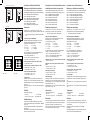
F1
⊥
F2
AC 9..36V~ / DC 12..48 V
+/~
-/~
Abb. 8a
F1
⊥
F2
Abb. 8b
Abb. 9a
L N L’
L
N
AC 230 V~
Abb. 9b
L’L N
Abb. 10a Abb. 10b
-
 1
1
-
 2
2


JUNG LS539 Bedienungsanleitung
- Typ
- Bedienungsanleitung
- Dieses Handbuch eignet sich auch für
in anderen Sprachen
- English: JUNG LS539 Operating instructions
- Nederlands: JUNG LS539 Handleiding
Verwandte Artikel
Andere Dokumente
-
Genius G60 G100 Bedienungsanleitung
-
-
-
-
Berker 6LE007685A Installationsanleitung
-
-
-
-