
11
11
1
ASRock K8Upgrade-VM800 Motherboard
EnglishEnglish
EnglishEnglish
English
Copyright Notice:Copyright Notice:
Copyright Notice:Copyright Notice:
Copyright Notice:
No part of this installation guide may be reproduced, transcribed, transmitted, or
translated in any language, in any form or by any means, except duplication of
documentation by the purchaser for backup purpose, without written consent of
ASRock Inc.
Products and corporate names appearing in this guide may or may not be registered
trademarks or copyrights of their respective companies, and are used only for
identification or explanation and to the owners’ benefit, without intent to infringe.
Disclaimer:Disclaimer:
Disclaimer:Disclaimer:
Disclaimer:
Specifications and information contained in this guide are furnished for informational
use only and subject to change without notice, and should not be constructed as a
commitment by ASRock. ASRock assumes no responsibility for any errors or
omissions that may appear in this guide.
With respect to the contents of this guide, ASRock does not provide warranty of any
kind, either expressed or implied, including but not limited to the implied warranties or
conditions of merchantability or fitness for a particular purpose.
In no event shall ASRock, its directors, officers, employees, or agents be liable for
any indirect, special, incidental, or consequential damages (including damages for
loss of profits, loss of business, loss of data, interruption of business and the like),
even if ASRock has been advised of the possibility of such damages arising from any
defect or error in the guide or product.
This device complies with Part 15 of the FCC Rules. Operation is subject to the
following two conditions:
(1) this device may not cause harmful interference, and
(2) this device must accept any interference received, including interference that
may cause undesired operation.
ASRock Website: http://www.asrock.com
Published April 2005
Copyright©2005 ASRock INC. All rights reserved.

22
22
2
ASRock K8Upgrade-VM800 Motherboard
EnglishEnglish
EnglishEnglish
English
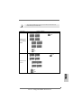
Motherboard LMotherboard L
Motherboard LMotherboard L
Motherboard L
ayoutayout
ayoutayout
ayout
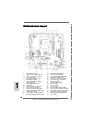
1 PS2_USB_PWR1 Jumper 18 System Panel Header (PANEL1)
2 ATX 12V Power Connector (ATX12V1) 19 Game Port Header (GAME1)
3 CPU Fan Connector (CPU_FAN1) 20 Chassis Speaker Header (SPEAKER 1)
4 754-Pin CPU Socket 21 USB 2.0 Header (USB67, Blue)
5 CPU Heatsink Retention Module 22 Chassis Fan Connector (CHA_FAN1)
6 North Bridge Controller 23 Clear CMOS Jumper (CLRCMOS2)
7 184-pin DDR DIMM Slots (DDR1- 2) 24 AGP Slot (1.5V_AGP1)
8 J9 / J10 / J15 Jumpers 25 COM Port Header (COM1)
9 Infrared Module Header (IR1) 26 AMR Slot (AMR1)
10 Flash Memory 27 PCI Slots (PCI1- 2)
11 ATX Power Connector (ATXPWR1) 28 JR1 / JL1 Jumpers
12 Floppy Connector (FLOPPY1) 29 Front Panel Audio Header (AUDIO1)
13 Primary IDE Connector (IDE1, Blue) 30 Future CPU Port (FUTURE_CPU_PORT1)
14 Secondary IDE Connector (IDE2, Black) 31 Internal Audio Connector: AUX1 (White)
15 South Bridge Controller 32 Internal Audio Connector: CD1 (Black)
16 Primary Serial ATA Connector (SATA1) 33 Shared USB 2.0 Header (USB45, Blue)
17 Secondary Serial ATA Connector (SATA2) 34 J1 - J8 Jumpers

33
33
3
ASRock K8Upgrade-VM800 Motherboard
EnglishEnglish
EnglishEnglish
English
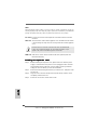
ASRock I/O PlusASRock I/O Plus
ASRock I/O PlusASRock I/O Plus
ASRock I/O Plus
TMTM
TMTM
TM
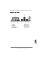
1 Parallel Port 7 USB 2.0 Ports (USB01)
2 RJ-45 Port 8 USB 2.0 Ports (USB23)
3 Line In (Light Blue) 9 VGA Port
4 Line Out (Lime) 10 PS/2 Keyboard Port (Purple)
5 Microphone (Pink) 11 PS/2 Mouse Port (Green)
6 Shared USB 2.0 Ports (USB45)

44
44
4
ASRock K8Upgrade-VM800 Motherboard
1.1.
1.1.
1.
IntroductionIntroduction
IntroductionIntroduction
Introduction
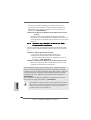
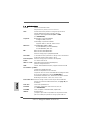
Thank you for purchasing ASRock K8Upgrade-VM800 motherboard, a reliable
motherboard produced under ASRock’s consistently stringent quality control. It de-
livers excellent performance with robust design conforming to ASRock’s commit-
ment to quality and endurance.
This Quick Installation Guide contains introduction of the motherboard and step-by-
step installation guide. More detailed information of the motherboard can be found in
the user manual presented in the Support CD.
Because the motherboard specifications and the BIOS software might
be updated, the content of this manual will be subject to change without
notice. In case any modifications of this manual occur, the updated
version will be available on ASRock website without further notice. You
may find the latest memory and CPU support lists on ASRock website
as well.
ASRock website http://www.asrock.com
1.11.1
1.11.1
1.1
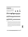
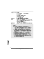
Package ContentsPackage Contents
Package ContentsPackage Contents
Package Contents
1 x ASRock K8Upgrade-VM800 Motherboard
(Micro ATX Form Factor: 9.0-in x 9.6-in, 22.9 cm x 24.4 cm)
1 x ASRock K8Upgrade-VM800 Quick Installation Guide
1 x ASRock K8Upgrade-VM800 Support CD
1 x Ultra ATA 66/100/133 IDE Ribbon Cable (80-conductor)
1 x 3.5-in Floppy Drive Ribbon Cable
1 x Serial ATA (SATA) Data Cable (Optional)
1 x Serial ATA (SATA) HDD Power Cable (Optional)
1 x ASRock I/O Plus
TM
Shield
1 x COM Port Bracket
1 x ASRock MR Card (Optional)
EnglishEnglish
EnglishEnglish
English

55
55
5
ASRock K8Upgrade-VM800 Motherboard
EnglishEnglish
EnglishEnglish
English
1.21.2
1.21.2
1.2
SpecificationsSpecifications
SpecificationsSpecifications
Specifications
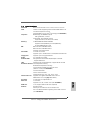
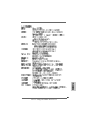
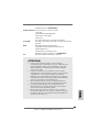
Platform: Micro ATX Form Factor: 9.0-in x 9.6-in, 22.9 cm x 24.4 cm
CPU: 754-Pin Socket Supporting advanced 64-bit AMD Athlon
TM
64
and 32-bit Sempron Processor
Supports AMD’s Cool ‘n’ Quiet
TM
Technology (see CAUTION 1)
Chipsets: North Bridge: VIA K8M800 Chipset
FSB @ 800 MHz / 1.6 GT/s
South Bridge: VIA VT8237R Chipset
Supports USB 2.0, ATA 133, SATA 1.5Gb/s
Memory: 2 x DDR DIMM Slots: DDR1 and DDR2
Support PC3200 (DDR400) / PC2700 (DDR333) /
PC2100 (DDR266), Max. 2GB
IDE: IDE1: ATA 133 / Ultra DMA Mode 6
IDE2: ATA 133 / Ultra DMA Mode 6
Supports up to 4 IDE Devices
Serial ATA: 2 x SATA Connectors
Supports up to 2 SATA Devices at 1.5Gb/s Data Transfer Rate
Floppy Port: Supports up to 2 Floppy Disk Drives
Audio: 5.1 channels AC’97 Audio
OnBoard VGA: Intergrated UniChrome PRO 3D/2D Graphics Controller
, supports DirectX 8.1
LAN: Speed: 802.3u (10/100 Ethernet), Supports Wake-On-LAN
Hardware Monitor: CPU Temperature Sensing
Motherboard Temperature Sensing
CPU Overheat Shutdown to Protect CPU Life
(ASRock U-COP)(see CAUTION 2)
CPU Fan Tachometer
Chassis Fan Tachometer
Voltage Monitoring: +12V, +5V, +3.3V, Vcore
Future CPU Port: Supports CPU upgrade from AMD 754-Pin CPU to
AMD 939-Pin CPU (see page 8 for details)
PCI Slots: 2 x PCI Slots, PCI Specification 2.2
AGP slot: 1 x AGP Slot
Supports 1.5V, 8X / 4X AGP Card (see CAUTION 3)
AMR slot: 1 slot, supports ASRock MR card (Optional)
USB 2.0: 8 USB 2.0 Ports:
6 Ready-to-Use USB 2.0 Ports on the I/O Panel
Plus 2 On-Board Headers Supporting 2 Extra USB 2.0 Ports
(see CAUTION 4)

66
66
6
ASRock K8Upgrade-VM800 Motherboard
EnglishEnglish
EnglishEnglish
English
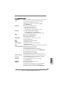
ASRock I/O Plus
TM
: 1 PS/2 Mouse Port, 1 PS/2 Keyboard Port
1 VGA Port
1 Parallel Port (ECP/EPP Support)
6 Ready-to-Use USB 2.0 Ports
1 RJ-45 Port
Audio Jack: Line In / Line Out / Microphone
COM Port: 1 COM Port Header to support a COM port module
BIOS: AMI Legal BIOS
Supports “Plug and Play”
ACPI 2.0 Compliance Wake Up Events
SMBIOS 2.3.1 Support
CPU Frequency Stepless Control
(only for advanced users’ reference, see CAUTION 5)
OS: Microsoft
®
Windows
®
98 SE / ME / 2000 / XP compliant
CAUTION!
1. For power-saving sake, it is strongly recommended to enable AMD’s Cool ‘n’
Quiet
TM
technology under Windows system. See APPENDIX on page 39 of
“User Manual” in the Support CD to enable AMD’s Cool ‘n’ Quiet
TM
technology.
2. While CPU overheat is detected, the system will automatically shutdown.
Before you resume the system, please check if the CPU fan on the motherboard
functions properly and unplug the power cord, then plug it back again. To
improve heat dissipation, remember to spray thermal grease between the
CPU and the heatsink when you install the PC system.
3. Do NOT use a 3.3V AGP card on the AGP slot of this motherboard!
It may cause permanent damage!
4. Power Management for USB 2.0 works fine under Microsoft
®
Windows
®
XP
SP1 / 2000 SP4. It may not work properly under Microsoft
®
Windows
®
98/ ME.
5. Although this motherboard offers stepless control, it is not recommended to
perform over-clocking. Frequencies other than the recommended CPU bus
frequencies may cause the instability of the system or damage the CPU.

77
77
7
ASRock K8Upgrade-VM800 Motherboard
2.2.
2.2.
2.
InstallationInstallation
InstallationInstallation
Installation
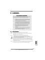
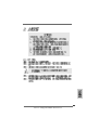
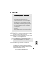
Pre-installation PrecautionsPre-installation Precautions
Pre-installation PrecautionsPre-installation Precautions
Pre-installation Precautions
Take note of the following precautions before you install mother-
board components or change any motherboard settings.
1. Unplug the power cord from the wall socket before touching any
component. Failure to do so may cause severe damage to the
motherboard, peripherals, and/or components.
2. To avoid damaging the motherboard components due to static
electricity, NEVER place your motherboard directly on the car-
pet or the like. Also remember to use a grounded wrist strap or
touch a safety grounded object before you handle components.
3. Hold components by the edges and do not touch the ICs.
4. Whenever you uninstall any component, place it on a
grounded antstatic pad or in the bag that comes with the
component.
5. When placing screws into the screw holes to secure the
motherboard to the chassis, please do not over-tighten the screws!
Doing so may damage the motherboard.
2.12.1
2.12.1
2.1
CPU InstallationCPU Installation
CPU InstallationCPU Installation
CPU Installation
Step 1. Unlock the socket by lifting the lever up to a 90° angle.
Step 2. Position the CPU directly above the socket such that its marked corner
matches the base of the socket lever.
Step 3. Carefully insert the CPU into the socket until it fits in place.
The CPU fits only in one correct orientation. DO NOT force the CPU
into the socket to avoid bending of the pins.
Step 4. When the CPU is in place, press it firmly on the socket while you push
down the socket lever to secure the CPU. The lever clicks on the side tab
to indicate that it is locked.
Step 5. Install CPU fan and heatsink. For proper installation, please kindly refer to
the instruction manuals of your CPU fan and heatsink vendors.
EnglishEnglish
EnglishEnglish
English

88
88
8
ASRock K8Upgrade-VM800 Motherboard
2.22.2
2.22.2
2.2
Installation of Memory Modules (DIMM)Installation of Memory Modules (DIMM)
Installation of Memory Modules (DIMM)Installation of Memory Modules (DIMM)
Installation of Memory Modules (DIMM)
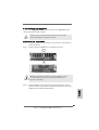
K8Upgrade-VM800 motherboard provides two 184-pin DDR (Double Data Rate)
DIMM slots.
Please make sure to disconnect power supply before adding or
removing DIMMs or the system components.
Step 1. Unlock a DIMM slot by pressing the retaining clips outward.
Step 2. Align a DIMM on the slot such that the notch on the DIMM matches the break
on the slot.
The DIMM only fits in one correct orientation. It will cause permanent
damage to the motherboard and the DIMM if you force the DIMM into the
slot at incorrect orientation.
Step 3. Firmly insert the DIMM into the slot until the retaining clips at both ends fully
snap back in place and the DIMM is properly seated.
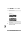
2.32.3
2.32.3
2.3
Expansion SlotsExpansion Slots
Expansion SlotsExpansion Slots
Expansion Slots
(Future CPU Port, PCI Slots, AGP Slot, and AMR Slots)(Future CPU Port, PCI Slots, AGP Slot, and AMR Slots)
(Future CPU Port, PCI Slots, AGP Slot, and AMR Slots)(Future CPU Port, PCI Slots, AGP Slot, and AMR Slots)
(Future CPU Port, PCI Slots, AGP Slot, and AMR Slots)
There are 1 Future CPU Port, 2 PCI slots, 1 AGP slot and 1 AMR slot on K8Upgrade-
VM800 motherboard.
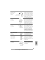
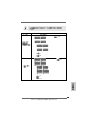
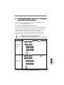
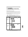
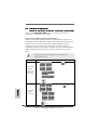
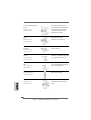
Future CPU Port (Yellow-Colored Port):
Future CPU Port allows you to upgrade your AMD 754-Pin CPU to AMD 939-Pin CPU by
installing an add-on ASRock 939CPU Board into this future CPU Port on K8Upgrade-
VM800 motherboard. Before you upgrade the 754-Pin CPU to the 939-Pin CPU, it is
necessary to adjust the jumper settings for those required jumpers on K8Upgrade-
VM800 motherboard. Please refer to the table below for the correct jumper settings.
EnglishEnglish
EnglishEnglish
English

99
99
9
ASRock K8Upgrade-VM800 Motherboard
This yellow-colored Future CPU Port is not an AGP slot! Please do
NOT insert any AGP card into it!
EnglishEnglish
EnglishEnglish
English
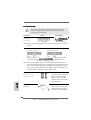
J10
CPU Type Jumper Settings
939-Pin CPU
(Using add-on
ASRock 939CPU
Board)
754-Pin CPU
(Default)
J1 J2
J3 J4
J5 J6
J7 J8
J1 J2
J3 J4
J5 J6
J7 J8
J15
J15
J9
J10
J9

1010
1010
10
ASRock K8Upgrade-VM800 Motherboard
EnglishEnglish
EnglishEnglish
English
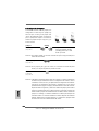
NOTE
When adjusting the jumper settings, you may use the tool, Jumper Cap Remover, to help you
removing the jumper caps more easily. This Jumper Cap Remover is bundled in your motherboard
package, and please follow the “Jumper Cap Remover Instruction” to use it properly.
PCI slots: PCI slots are used to install expansion cards that have the 32-bit PCI
interface.
AGP slot: The AGP slot is used to install a graphics card. The ASRock AGP slot has
a special design of clasp that can securely fasten the inserted graphics
card.
Please do NOT use a 3.3V AGP card on the AGP slot of this motherboard!
It may cause permanent damage! For the voltage information of your
graphics card, please check with the graphics card vendors.
AMR slot: AMR slot is used to insert an ASRock MR card (optional) with v.92
Modem functionality.
Installing an expansion cardInstalling an expansion card
Installing an expansion cardInstalling an expansion card
Installing an expansion card
Step 1. Before installing the expansion card, please make sure that the power
supply is switched off or the power cord is unplugged. Please read the
documentation of the expansion card and make necessary hardware
settings for the card before you start the installation.
Step 2. Remove the bracket facing the slot that you intend to use. Keep the screw
for later use.
Step 3. Align the card connector with the slot and press firmly until the card is
completely seated on the slot.
Step 4. Fasten the card to the chassis with screws.

1111
1111
11
ASRock K8Upgrade-VM800 Motherboard
Short Open
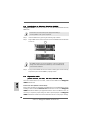
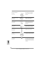
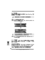
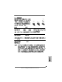
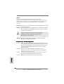
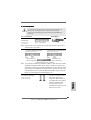
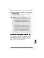
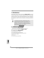
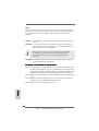
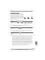
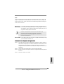
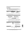
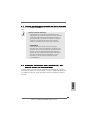
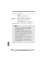
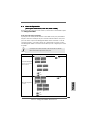
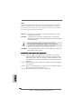
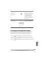
2.4 Jumpers Setup2.4 Jumpers Setup
2.4 Jumpers Setup2.4 Jumpers Setup
2.4 Jumpers Setup
The illustration shows how jumpers are
setup. When the jumper cap is placed on
pins, the jumper is “Short”. If no jumper cap
is placed on the pins, the jumper is “Open”.
The illustration shows a 3-pin jumper whose
pin1 and pin2 are “Short” when jumper cap
is placed on these 2 pins.
Jumper Setting
PS2_USB_PWR1 Short pin2, pin3 to enable
(see p.2, No. 1) +5VSB (standby) for PS/2 or
USB wake up events.
Note: To select +5VSB, it requires 2 Amp and higher standby current provided by
power supply.
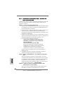
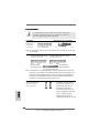
JR1 / JL1 Jumper
(see p.2, No. 28)
Note: If the jumpers JR1 and JL1 are short, both the front panel and the rear panel
audio connectors can work.
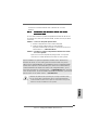
Clear CMOS Jumper
(CLRCMOS2)
(see p.2, No. 23)
Note: CLRCMOS2 allows you to clear the data in CMOS. The data in CMOS includes
system setup information such as system password, date, time, and system
setup parameters. To clear and reset the system parameters to default setup,
please turn off the computer andunplug the power cord from the power
supply. After waiting for 15 seconds, use a jumper cap to short the Clear
CMOS jumper for 5 seconds. After shorting the Clear CMOS jumper, please
remove the jumper cap. However, please do not clear the CMOS right after you
update the BIOS. If you need to clear the CMOS when you just finish updating
the BIOS, you must boot up the system first, and then shut it down before you
do the clear-CMOS action.
EnglishEnglish
EnglishEnglish
English

1212
1212
12
ASRock K8Upgrade-VM800 Motherboard
EnglishEnglish
EnglishEnglish
English
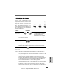
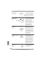
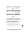
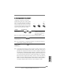
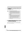
connect the black end
to the IDE devices
connect the blue end
to the motherboard
the red-striped side to Pin1
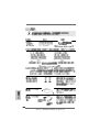
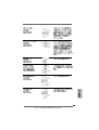
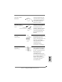
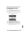
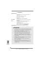
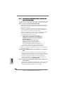
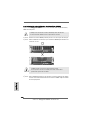
2.5 Connectors2.5 Connectors
2.5 Connectors2.5 Connectors
2.5 Connectors
Connectors are NOT jumpers. DO NOT place jumper caps over these
connectors. Placing jumper caps over the connectors will cause perma-
nent damage of the motherboard!
Connector Figure Description
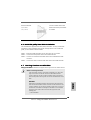
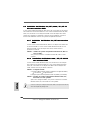
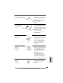
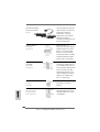
Floppy Connector
(33-pin FLOPPY1)
(see p.2, No. 12)
Note: Make sure the red-striped side of the cable is plugged into Pin1 side of the
connector.
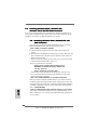
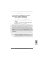
Primary IDE Connector (Blue) Secondary IDE Connector (Black)
(39-pin IDE1, see p.2, No. 13) (39-pin IDE2, see p.2, No. 14)
80-conductor, ATA 66/100/133 cable
Note: If you use only one IDE device on this motherboard, please set the IDE
device as “Master”. Please refer to the instruction of your IDE device vendor
for the details. Besides, to optimize compatibility and performance, please
connect your hard disk drive to the primary IDE connector (IDE1, blue) and
CD-ROM to the secondary IDE connector (IDE2, black).
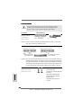
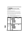
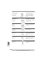
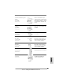
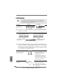
Serial ATA Connectors These two Serial ATA (SATA)
(SATA1: see p.2, No. 16) connectors support SATA data
(SATA2: see p.2, No. 17) cables for internal storage
devices. The current SATA
interface allows up to 1.5 Gb/s
data transfer rate.
Serial ATA (SATA) Either end of the SATA data
Data Cable cable can be connected to the
SATA hard disk or the SATA
connector on the motherboard.
SATA2
SATA1

1313
1313
13
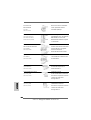
ASRock K8Upgrade-VM800 Motherboard
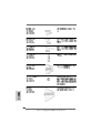
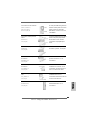
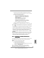
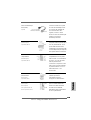
Serial ATA (SATA) Please connect the black end of
Power Cable SATA power cable to the power
(Optional) connector on each drive. Then
connect the white end of SATA
power cable to the power
connector of the power supply.
USB 2.0 Header ASRock I/O Plus
TM
provides you
(9-pin USB67) 6 ready-to-use USB 2.0 ports on
(see p.2, No. 21) the rear panel. If the rear USB
ports are not sufficient, this
USB 2.0 header is available to
support 2 extra USB 2.0 ports.
Shared USB 2.0 Header This USB45 header is shared
(9-pin USB45) with the USB 2.0 ports 4,5 on
(see p.2, No. 33) ASRock I/O Plus
TM
. When using
the front panel USB ports by
attaching the front panel USB
cable to this header (USB45), the
USB ports 4,5 on ASRock I/O
Plus
TM
will not be able to function.
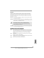
Infrared Module Header This header supports an
(5-pin IR1) optional wireless transmitting and
(see p.2, No. 9) receiving infrared module.
Internal Audio Connectors These connectors allow you to
(4-pin CD1, 4-pin AUX1) receive stereo audio input from
(CD1: see p.2, No. 32) sound sources such as a CD-
(AUX1: see p.2, No. 31) ROM, DVD-ROM, TV tuner card,
or MPEG card.
Front Panel Audio Header This is an interface for front panel
(9-pin AUDIO1) audio cable that allows conve-
(see p.2, No. 29) nient connection and control of
audio devices.
CD1
AUX1
connect to the
power supply
connect to the SATA
HDD power connector
EnglishEnglish
EnglishEnglish
English

1414
1414
14
ASRock K8Upgrade-VM800 Motherboard
EnglishEnglish
EnglishEnglish
English
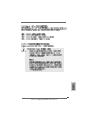
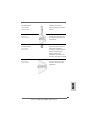
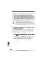
System Panel Header This header accommodates
(9-pin PANEL1) several system front panel
(see p.2, No. 18) functions.
Chassis Speaker Header Please connect the chassis(4-
pin SPEAKER 1) speaker to this header.
(see p.2, No. 20)
Chassis Fan Connector Please connect a chassis fan
(3-pin CHA_FAN1) cable to this connector and
(see p.2, No. 22) match the black wire to the
ground pin.
CPU Fan Connector Please connect a CPU fan cable
(3-pin CPU_FAN1) to this connector and match the
(see p.2, No. 3) black wire to the ground pin.
ATX Power Connector Please connect an ATX power
(20-pin ATXPWR1) supply to this connector.
(see p.2, No. 11)
COM Port Header This COM port header is used
(9-pin COM1) to support a COM port module.
(see p.2, No. 25)
ATX 12V Power Connector Please note that it is necessary
(4-pin ATX12V1) to connect a power supply with
(see p.2, No. 2) ATX 12V plug to this connector.
Failing to do so will cause power
up failure.

1515
1515
15
ASRock K8Upgrade-VM800 Motherboard
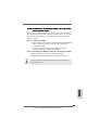
Game Port Header Connect a Game cable to this
(15-pin GAME1) header if the Game port bracket
(see p.2, No. 19) is installed.
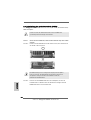
2.62.6
2.62.6
2.6
Serial ASerial A
Serial ASerial A
Serial A
TT
TT
T
A (SAA (SA
A (SAA (SA
A (SA
TT
TT
T
A) Hard Disks InstallationA) Hard Disks Installation
A) Hard Disks InstallationA) Hard Disks Installation
A) Hard Disks Installation
This motherboard supports Serial ATA (SATA) hard disks. You may install SATA
hard disks on this motherboard for internal storage devices. This section will
guide you to install the SATA hard disks.
STEP 1: Install the SATA hard disks into the drive bays of your chassis.
STEP 2: Connect the SATA power cable to the SATA hard disk.
STEP 3: Connect one end of the SATA data cable to the motherboard’s SATA
connector.
STEP 4: Connect the other end of the SATA data cable to the SATA hard disk.
2.72.7
2.72.7
2.7
Hot Plug FHot Plug F
Hot Plug FHot Plug F
Hot Plug F
unction for SAunction for SA
unction for SAunction for SA
unction for SA
TT
TT
T
A HDDsA HDDs
A HDDsA HDDs
A HDDs
K8Upgrade-VM800 motherboard supports Hot Plug function for SATA devices.
What is Hot Plug Function?
If the SATA HDDs are NOT set for RAID configuration, it is called “Hot
Plug” for the action to insert and remove the SATA HDDs while the
system is still power-on and in working condition. However, please note
that it cannot perform Hot Plug if the OS has been installed into the SATA
HDD.
WARNING!
Although this motherboard supports Hot Plug function for SATA devices,
there are still some limitation. Please ensure to read the instruction in the
Support CD before you use Hot Plug function. Failure to do so may lose
the data in the SATA HDDs or damage the SATA HDDs. For the detailed
instruction, please refer to the document in the Support CD at the
following path:
..\ SATA RAID BIOS
EnglishEnglish
EnglishEnglish
English

1616
1616
16
ASRock K8Upgrade-VM800 Motherboard
EnglishEnglish
EnglishEnglish
English
2.82.8
2.82.8
2.8
Installing Windows 2000 / Windows XP /Installing Windows 2000 / Windows XP /
Installing Windows 2000 / Windows XP /Installing Windows 2000 / Windows XP /
Installing Windows 2000 / Windows XP /
Windows XP 64-bit With RAID FunctionsWindows XP 64-bit With RAID Functions
Windows XP 64-bit With RAID FunctionsWindows XP 64-bit With RAID Functions
Windows XP 64-bit With RAID Functions
If you want to install Windows 2000 / Windows XP / Windows XP-64bit OS on
your system with RAID functions, please refer to the below methods for proper
installation according to the different Windows OS versions.
2.8.12.8.1
2.8.12.8.1
2.8.1
Installing Windows 2000 / Windows XP withInstalling Windows 2000 / Windows XP with
Installing Windows 2000 / Windows XP withInstalling Windows 2000 / Windows XP with
Installing Windows 2000 / Windows XP with
RAID FunctionsRAID Functions
RAID FunctionsRAID Functions
RAID Functions
If you want to install Windows 2000 / Windows XP OS on your SATA
HDDs with RAID functions, please follow the below steps.
STEP 1: Make a SATA Driver Diskette.
A. Insert the ASRock Support CD into your optical drive to boot your
system.
B. During POST at the beginning of system boot-up, press <F11> key, and
then a window for boot devices selection appears. Please select CD-
ROM as the boot device.
C. When you see the message on the screen, “Do you want to generate
Serial ATA driver diskette [YN]?”, press <Y>.
D. Then you will see these messages,
Please insert a diskette into the floppy drive.
WARNING! Formatting the floppy diskette will
lose ALL data in it!
Start to format and copy files [YN]?
Please insert a floppy diskette into the floppy drive, and press <Y>.
E. The system will start to format the floppy diskette and copy SATA
drivers into the floppy diskette.
STEP 2: Use “SATA RAID BIOS” to set RAID configuration.
Before you start to configure the RAID function, you need to check the
installation guide in the Support CD for proper configuration. Please refer
to the document in the Support CD, “Guide to SATA Hard Disks Installation
and RAID Configuration”, which is located in the folder at the following
path: .. \ SATA RAID BIOS
STEP 3: Install Windows 2000 / Windows XP OS on your system.
After making a SATA driver diskette and using “SATA RAID BIOS” to set
RAID configuration, you can start to install Windows 2000 / Windows XP
on your system.

1717
1717
17
ASRock K8Upgrade-VM800 Motherboard
EnglishEnglish
EnglishEnglish
English
2.8.22.8.2
2.8.22.8.2
2.8.2
Installing Windows XP 64-bit WithInstalling Windows XP 64-bit With
Installing Windows XP 64-bit WithInstalling Windows XP 64-bit With
Installing Windows XP 64-bit With
RAIDRAID
RAIDRAID
RAID
FunctionsFunctions
FunctionsFunctions
Functions
If you want to install Windows XP 64-bit OS on your SATA HDDs with RAID
functions, please follow the below steps.
STEP 1: Make a SATA Driver Diskette.
A. Insert the floppy diskette into your floppy drive.
B. Copy the SATA 64-bit drivers to your floppy diskette.
The SATA 64-bit drivers are located at the following path in the Support CD:
.. \ 64bit SATA Driver
STEP 2: Install Windows XP 64-bit OS on your system.
After making a SATA driver diskette, you can start to install Windows XP 64-
bit on your system.
After the installation of Windows 2000 / Windows XP / Windows XP 64-bit OS,
if you want to manage RAID functions, you are allowed to use both “SATA RAID
BIOS” and “VIA RAID Tool” for RAID configuration. Please refer to the document
in the Support CD, “Guide to SATA Hard Disks Installation and RAID Configuration”,
which is located in the folder at the following path: .. \ SATA RAID BIOS and the
document in the support CD, “Guide to VIA RAID Tool”, which is located in the
folder at the following path: .. \ VIA RAID Tool
1. Windows 98 / Windows ME does not support RAID functions.
2. If you want to use “VIA RAID Tool” in Windows environment, please install
SATA drivers from the Support CD again so that “VIA RAID Tool” will be
installed to your system as well.

1818
1818
18
ASRock K8Upgrade-VM800 Motherboard
EnglishEnglish
EnglishEnglish
English
2.92.9
2.92.9
2.9
Installing Windows 98 / ME / 2000 / XP / XP 64-bitInstalling Windows 98 / ME / 2000 / XP / XP 64-bit
Installing Windows 98 / ME / 2000 / XP / XP 64-bitInstalling Windows 98 / ME / 2000 / XP / XP 64-bit
Installing Windows 98 / ME / 2000 / XP / XP 64-bit
Without RAID FunctionsWithout RAID Functions
Without RAID FunctionsWithout RAID Functions
Without RAID Functions
If you want to install Windows 98 / ME / 2000 / XP / XP 64-bit on your SATA HDDs
without RAID functions or you want to install Windows 98 / ME / 2000 / XP / XP
64-bit on your IDE HDDs instead of SATA HDDs, please refer to the below methods
for proper installation according to the different Windows OS versions.
2.9.1 2.9.1
2.9.1 2.9.1
2.9.1
Installing Windows 98 / ME Without RAID Installing Windows 98 / ME Without RAID
Installing Windows 98 / ME Without RAID Installing Windows 98 / ME Without RAID
Installing Windows 98 / ME Without RAID
Functions Functions
Functions Functions
Functions
If you want to install Windows 98 / ME on your SATA HDDs without RAID
functions or you want to install Windows 98 / ME on your IDE HDDs instead
of SATA HDDs, please follow the below steps.
STEP 1: Install Windows 98 / ME OS on your system.
You can start to install Windows 98 / ME on your system directly.
2.9.2 2.9.2
2.9.2 2.9.2
2.9.2
Installing Windows XP / 2000 / XP 64-bit Installing Windows XP / 2000 / XP 64-bit
Installing Windows XP / 2000 / XP 64-bit Installing Windows XP / 2000 / XP 64-bit
Installing Windows XP / 2000 / XP 64-bit
Without RAID Functions Without RAID Functions
Without RAID Functions Without RAID Functions
Without RAID Functions
If you want to install Windows XP / 2000 / XP 64-bit on your SATA HDDs
without RAID functions or you want to install Windows XP / 2000 / XP 64-bit
on your IDE HDDs instead of SATA HDDs, please follow the below steps.
STEP 1: Set Up BIOS.
A. Enter BIOS SETUP UTILITY Advanced screen IDE Configuration.
B. Set the “SATA Operation Mode” option from [RAID] to [non-RAID].
STEP 2: Install Windows 2000 / XP / XP 64-bit OS on your system.
After setting up BIOS, you can start to install Windows 2000 / XP / XP
64-bit on your system.
If you don’t want to set up RAID functions, there is no need to make a SATA
driver diskette.

1919
1919
19
ASRock K8Upgrade-VM800 Motherboard
3. BIOS Information3. BIOS Information
3. BIOS Information3. BIOS Information
3. BIOS Information
The Flash Memory on the motherboard stores BIOS Setup Utility. When you start up
the computer, please press <F2> during the Power-On-Self-Test (POST) to enter
BIOS Setup utility; otherwise, POST continues with its test routines. If you wish to
enter BIOS Setup after POST, please restart the system by pressing <Ctl> + <Alt> +
<Delete>, or pressing the reset button on the system chassis.
The BIOS Setup program is designed to be user-friendly. It is a menu-driven program,
which allows you to scroll through its various sub-menus and to select among the
predetermined choices. For the detailed information about BIOS Setup, please refer
to the User Manual (PDF file) contained in the Support CD.
4. Software Suppor4. Software Suppor
4. Software Suppor4. Software Suppor
4. Software Suppor
t CD informationt CD information
t CD informationt CD information
t CD information
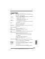
This motherboard supports various Microsoft
®
Windows
®
operating systems: 98 SE/
ME / 2000 / XP. The Support CD that came with the motherboard contains necessary
drivers and useful utilities that will enhance motherboard features.
To begin using the Support CD, insert the CD into your CD-ROM drive. It will display
the Main Menu automatically if “AUTORUN” is enabled in your computer. If the Main
Menu does not appear automatically, locate and double-click on the file “ASSETUP.
EXE” from the “BIN” folder in the Support CD to display the menus.
EnglishEnglish
EnglishEnglish
English

2020
2020
20
ASRock K8Upgrade-VM800 Motherboard
Seite wird geladen ...
Seite wird geladen ...
Seite wird geladen ...
Seite wird geladen ...
Seite wird geladen ...
Seite wird geladen ...
Seite wird geladen ...
Seite wird geladen ...
Seite wird geladen ...
Seite wird geladen ...
Seite wird geladen ...
Seite wird geladen ...
Seite wird geladen ...
Seite wird geladen ...
Seite wird geladen ...
Seite wird geladen ...
Seite wird geladen ...
Seite wird geladen ...
Seite wird geladen ...
Seite wird geladen ...
Seite wird geladen ...
Seite wird geladen ...
Seite wird geladen ...
Seite wird geladen ...
Seite wird geladen ...
Seite wird geladen ...
Seite wird geladen ...
Seite wird geladen ...
Seite wird geladen ...
Seite wird geladen ...
Seite wird geladen ...
Seite wird geladen ...
Seite wird geladen ...
Seite wird geladen ...
Seite wird geladen ...
Seite wird geladen ...
Seite wird geladen ...
Seite wird geladen ...
Seite wird geladen ...
Seite wird geladen ...
Seite wird geladen ...
Seite wird geladen ...
Seite wird geladen ...
Seite wird geladen ...
Seite wird geladen ...
Seite wird geladen ...
Seite wird geladen ...
Seite wird geladen ...
Seite wird geladen ...
Seite wird geladen ...
Seite wird geladen ...
Seite wird geladen ...
Seite wird geladen ...
Seite wird geladen ...
Seite wird geladen ...
Seite wird geladen ...
Seite wird geladen ...
Seite wird geladen ...
Seite wird geladen ...
Seite wird geladen ...
Seite wird geladen ...
Seite wird geladen ...
Seite wird geladen ...
Seite wird geladen ...
Seite wird geladen ...
Seite wird geladen ...
Seite wird geladen ...
Seite wird geladen ...
Seite wird geladen ...
Seite wird geladen ...
Seite wird geladen ...
Seite wird geladen ...
Seite wird geladen ...
Seite wird geladen ...
Seite wird geladen ...
Seite wird geladen ...
Seite wird geladen ...
Seite wird geladen ...
Seite wird geladen ...
Seite wird geladen ...
Seite wird geladen ...
Seite wird geladen ...
Seite wird geladen ...
Seite wird geladen ...
Seite wird geladen ...
Seite wird geladen ...
Seite wird geladen ...
Seite wird geladen ...
Seite wird geladen ...
Seite wird geladen ...
Seite wird geladen ...
Seite wird geladen ...
Seite wird geladen ...
Seite wird geladen ...
Seite wird geladen ...
Seite wird geladen ...
Seite wird geladen ...
Seite wird geladen ...
Seite wird geladen ...
Seite wird geladen ...
Seite wird geladen ...
Seite wird geladen ...
Seite wird geladen ...
Seite wird geladen ...
Seite wird geladen ...
Seite wird geladen ...
Seite wird geladen ...
Seite wird geladen ...
-
 1
1
-
 2
2
-
 3
3
-
 4
4
-
 5
5
-
 6
6
-
 7
7
-
 8
8
-
 9
9
-
 10
10
-
 11
11
-
 12
12
-
 13
13
-
 14
14
-
 15
15
-
 16
16
-
 17
17
-
 18
18
-
 19
19
-
 20
20
-
 21
21
-
 22
22
-
 23
23
-
 24
24
-
 25
25
-
 26
26
-
 27
27
-
 28
28
-
 29
29
-
 30
30
-
 31
31
-
 32
32
-
 33
33
-
 34
34
-
 35
35
-
 36
36
-
 37
37
-
 38
38
-
 39
39
-
 40
40
-
 41
41
-
 42
42
-
 43
43
-
 44
44
-
 45
45
-
 46
46
-
 47
47
-
 48
48
-
 49
49
-
 50
50
-
 51
51
-
 52
52
-
 53
53
-
 54
54
-
 55
55
-
 56
56
-
 57
57
-
 58
58
-
 59
59
-
 60
60
-
 61
61
-
 62
62
-
 63
63
-
 64
64
-
 65
65
-
 66
66
-
 67
67
-
 68
68
-
 69
69
-
 70
70
-
 71
71
-
 72
72
-
 73
73
-
 74
74
-
 75
75
-
 76
76
-
 77
77
-
 78
78
-
 79
79
-
 80
80
-
 81
81
-
 82
82
-
 83
83
-
 84
84
-
 85
85
-
 86
86
-
 87
87
-
 88
88
-
 89
89
-
 90
90
-
 91
91
-
 92
92
-
 93
93
-
 94
94
-
 95
95
-
 96
96
-
 97
97
-
 98
98
-
 99
99
-
 100
100
-
 101
101
-
 102
102
-
 103
103
-
 104
104
-
 105
105
-
 106
106
-
 107
107
-
 108
108
-
 109
109
-
 110
110
-
 111
111
-
 112
112
-
 113
113
-
 114
114
-
 115
115
-
 116
116
-
 117
117
-
 118
118
-
 119
119
-
 120
120
-
 121
121
-
 122
122
-
 123
123
-
 124
124
-
 125
125
-
 126
126
-
 127
127
-
 128
128


ASROCK K8UPGRADE-VM800 Bedienungsanleitung
- Typ
- Bedienungsanleitung
- Dieses Handbuch eignet sich auch für
in anderen Sprachen
Verwandte Artikel
-
ASROCK K7VT4A PRO Bedienungsanleitung
-
ASROCK K7NF2-RAID Bedienungsanleitung
-
ASROCK PV4V88PLUS Bedienungsanleitung
-
ASROCK 775V88 PLUS Bedienungsanleitung
-
ASROCK P4VM890 Bedienungsanleitung
-
ASROCK K7S41GX Bedienungsanleitung
-
ASROCK 939Dual-VSTA Installationsanleitung
-
-
ASROCK K7VM3 Bedienungsanleitung
-
ASROCK 939Dual-SATA2 Bedienungsanleitung