Gemini MM-04 Bedienungsanleitung
- Kategorie
- Audiomischer
- Typ
- Bedienungsanleitung

OPERATIONS MANUAL
BEDIENUNGSHANDBUCH
MANUAL DEL OPERADOR
MANUEL D’INSTRUCTIONS
4U 19" Rack Mounted Club Mixer
19"- 4HE- CLUBMIXER FÜR RACKEINBAU
MEZCLADOR CLUB DE 4U PARA MONTAR EN RACK 19"
CONSOLE DE MIXAGE CLUB RACKABKE 19'' X 4U

CAUTION: This product satisfies FCC regulations when shielded cables and connec-
tors are used to connect the unit to other equipment. To prevent electromagnetic
interference with electric appliances such as radios and televisions, use shielded
cables and connectors for connections.
The exclamation point within an equilateral triangle is intended to alert the user to
the presence of important operating and maintenance (servicing) instructions in
the literature accompanying the appliance.
The lightening flash with arrowhead symbol, within an equilateral triangle, is
intended to alert the user to the presence of uninsulated “dangerous voltage” with-
in the product’s enclosure that may be of sufficient magnitude to constitute a risk
of electric shock to persons.
READ INSTRUCTIONS: All the safety and operating instructions should be read
before the product is operated.
RETAIN INSTRUCTIONS: The safety and operating instructions should be retained
for future reference.
HEED WARNINGS: All warnings on the product and in the operating instructions
should be adhered to.
FOLLOW INSTRUCTIONS: All operating and use instructions should be followed.
CLEANING: The product should be cleaned only with a polishing cloth or a soft dry
cloth. Never clean with furniture wax, benzine, insecticides or other volatile liquids
since they may corrode the cabinet.
ATTACHMENTS: Do not use attachments not recommended by the product manu-
acturer as they may cause hazards.
WATER AND MOISTURE: Do not use this product near water, for example, near a
bathtub, wash bowl, kitchen sink, or laundry tub; in a wet basement; or near a
swimming pool; and the like.
ACCESSORIES: Do not place this product on an unstable cart, stand, tripod, brack-
et, or table. The product may fall, causing serious injury to a child or adult, and
serious damage to the product. Use only with a cart, stand, tripod, bracket, or table
recommended by the manufacturer, or sold with the product. Any mounting of the
product should follow the manufacturer’s instructions, and should use a mounting
accessory recommended by the manufacturer.
CART: A product and cart combination should be moved with care. Quick stops,
excessive force, and uneven surfaces may cause the product and cart combina-
tion to overturn. See Figure A.
VENTILATION: Slots and openings in the cabinet are provided for ventilation and to
ensure reliable operation of the product and to protect it from overheating, and
these openings must not be blocked or covered. The openings should never be
blocked by placing the product on a bed, sofa, rug, or other similar surface. This
product should not be placed in a built-in installation such as a bookcase or rack
unless proper ventilation is provided or the manufacturer’s instructions have been
adhered to.
POWER SOURCES: This product should be operated only from the type of power
source indicated on the marking label. If you are not sure of the type of power sup-
ply to your home, consult your product dealer or local power company.
LOCATION: The appliance should be installed in a stable location.
NON-USE PERIODS: The power cord of the appliance should be unplugged from the
outlet when left unused for a long period of time.
GROUNDING OR POLARIZATION:
• If this product is equipped with a polarized alternating current line plug (a plug
having one blade wider than the other), it will fit into the outlet only one way. This
is a safety feature. If you are unable to insert the plug fully into the outlet, try
reversing the plug. If the plug should still fail to fit, contact your electrician to
replace your obsolete outlet. Do not defeat the safety purpose of the polarized
plug.
• If this product is equipped with a three-wire grounding type plug, a plug having
a third (grounding) pin, it will only fit into a grounding type power outlet. This is a
safety feature. If you are unable to insert the plug into the outlet, contact your elec-
trician to replace your obsolete outlet. Do not defeat the safety purpose of the
grounding type plug.
POWER-CORD PROTECTION: Power-supply cords should be routed so that they
are not likely to be walked on or pinched by items placed upon or against them,
paying particular attention to cords at plugs, convenience receptacles, and the
point where they exit from the product.
OUTDOOR ANTENNA GROUNDING: If an outside antenna or cable system is con-
nected to the product, be sure the antenna or cable system is grounded so as to
provide some protection against voltage surges and built-up static charges. Article
810 of the National Electrical Code, ANSI/NFPA 70, provides information with
regard to proper grounding of the mast and supporting structure, grounding of the
lead-in wire to an antenna discharge unit, size of grounding conductors, location
of antenna-discharge unit, connection to grounding electrodes, and requirements
for the grounding electrode. See Figure B.
LIGHTENING: For added protection for this product during a lightening storm, or
when it is left unattended and unused for long periods of time, unplug it from the
wall outlet and disconnect the antenna or cable system. This will prevent damage
to the product due to lightening and power-line surges.
POWER LINES: An outside antenna system should not be located in the vicinity of
overhead power lines or other electric light or power circuits, or where it can fall
into such power lines or circuits. When installing an outside antenna system,
extreme care should be taken to keep from touching such power lines or circuits
as contact with them might be fatal.
OVERLOADING: Do not overload wall outlets, extension cords, or integral conven-
ience receptacles as this can result in a risk of fire or electric shock.
OBJECT AND LIQUID ENTRY: Never push objects of any kind into this product
through openings as they may touch dangerous voltage points or short-out parts
that could result in a fire or electric shock. Never spill liquid of any kind on the
product.
SERVICING: Do not attempt to service this product yourself as opening or removing
covers may expose you to dangerous voltage or other hazards. Refer all servic-
ing to qualified service personnel.
DAMAGE REQUIRING SERVICE: Unplug this product from the wall outlet and refer
servicing to qualified service personnel under the following conditions:
• When the power-supply cord or plug is damaged.
• If liquid has been spilled, or objects have fallen into the product.
• If the product has been exposed to rain or water.
• If the product does not operate normally by following the operating instructions.
Adjust only those controls that are covered by the operating instructions as an
improper adjustment of other controls may result in damage and will often require
extensive work by a qualified technician to restore the product to its normal oper-
ation.
• If the product has been dropped or damaged in any way.
• When the product exhibits a distinct change in performance, this indicates a
need for service.
REPLACEMENT PARTS: When replacement parts are required, be sure the service
technician has used replacement parts specified by the manufacturer or have the
same characteristics as the original part. Unauthorized substitutions may result in
fire, electric shock, or other hazards.
SAFETY CHECK: Upon completion of any service or repairs to this product, ask the
service technician to perform safety checks to determine that the product is in
proper operating condition.
WALL OR CEILING MOUNTING: The product should not be mounted to a wall or
ceiling.
HEAT: The product should be situated away from heat sources such as radiators,
heat registers, stoves, or other products (including amplifiers) that produce heat.
MULTI LANGUAGE INSTRUCTIONS
ENGLISH...........................................................................................................................................................................................................................................................................PAGE 4
DEUTSCH............................................................................................................................................................................................................................................................................PAGE 7
ESPAÑOL........................................................................................................................................................................................................................................................................................................................................................................PAGE 10
FRANCAIS....................................................................................................................................................................................................................................................................................................................................................................PAGE 13
PLEASE READ BEFORE USING APPLIANCE, IMPORTANT WARNING & SAFETY INSTRUCTIONS!
RISK OF ELECTRICAL SHOCK DO NOT OPEN!
CAUTION
(2)

(3)

(44)
Congratulations on purchasing a Gemini MM-04 4U 19", 4
channel, rack mounted audio EFX mixer. This state of the art
mixer is backed by a 3 year warranty, excluding crossfader. The
crossfader is backed by a separate 90 day warranty. Prior to use
we suggest that you carefully read all the instructions.
- 4U 19" rack mounted audio EFX mixer
- 4 stereo channels
- 6 line, 3 mic, 2 convertible phono/line RCA inputs
- Master, zone & record RCA outputs
- Balanced master output
FACE:
- 3 band rotary line EQ control per channel with cut feature
- Bright blue LCD display
- 26 DSP effects module with a wide range of parameters
- Dry/Wet fader control
- Rotary control EFX selector
- Rotary parameter control
- Large backlit soft touch on/off EFX button
- Fully removable, user replaceable Rail Glide cross fader
- Assignable cross fader
- Rotary gain control per channel
- Dual VU display with bright LED
- Push-button cue section with cue/PGM fader control
- Rotary master, zone, balance and cue volume controls
- XLR-1/4" combo mic input & 2 x 1/4" Mic inputs
- 2 band rotary mic EQ controls
- Rotary mic volume control
- Auto talk-over feature
- Face plate located 1/4" headphone jack
1. All operating instructions should be read before using this
equipment.
2. To reduce the risk of electrical shock, do not open the unit.
Please refer servicing to a Gemini qualified service technician.
3. Do not expose this unit to direct sunlight or to a heat source
such as a radiator or stove.
4. This unit should be cleaned only with a damp cloth. Avoid sol-
vents or other cleaning detergents.
5. When moving this equipment, it should be placed in its origi-
nal carton and packaging. This will reduce the risk of damage
during transit.
6. DO NOT EXPOSE THIS UNIT TO RAIN OR MOISTURE.
7. DO NOT USE ANY SPRAY CLEANER OR LUBRICANT ON
ANY CONTROLS OR SWITCHES.
1. Before plugging this unit into any outlet, make sure that the
VOLTAGE SELECTION SWITCH (1) is set to the proper volt-
age. To change the selection, unscrew the hard plastic protec-
tive top with a Phillips head screw driver. Then use a flat head
screw driver to move the switch to the proper selection
(115V/230V).
2. Located on the rear panel is the POWER CORD (2). Before
plugging the POWER CORD (2) into a power outlet, make sure
the POWER SWITCH (64) located on the face panel is turned
off.
NOTE: LOCATED BY THE POWER CORD (2) JACK IS A 250V FUSE (67) TO
PROTECT AGAINST ELECTRICAL SURGES. TO REPLACE THE FUSE,
PLACE A FLAT HEAD SCREWDRIVER INTO THE GROOVE LOCATED INSIDE
THE POWER CORD JACK (2) AND POP THE FUSE OUT. REPLACE THE FUSE
WITH ONLY A 250V FUSE.
3. The MM-04 has 4 sets of outputs:
- The MASTER OUTPUT (4) jacks also connect to the main
amplifier with RCA cables.
- The BALANCED MASTER OUTPUT (3) jacks connect the
mixer to main amplifier using standard cables with 1/4" TRS
connectors. We recommend using balanced cables if the dis-
tance to your amp is 10 feet or more.
- The REC OUTPUT (5) jacks can be used to connect the mixer
to the record input of your recording unit, thus enabling you to
record your mix by connecting these units with RCA cables.
- The ZONE OUTPUT (6) jacks allow the connection of an addi-
tional amplifier with RCA cables.
4. Located on the rear panel are 2 PHONO(PH)/LINE(LN) con-
vertible RCA inputs (13, 10), and 4 LN RCA inputs (16, 14, 11,
7). The CONVERTIBLE RCA INPUTS (13, 10) for CHANNEL
(CH) 2 (35) & CH 3 (42) allow PH and LN level equipment to be
connected to the mixer. To adjust the CONVERTER
SWITCH(es) (9, 12), just flip the switch up to operate PH 1 or
PH 2. Flip the switch down to operate through LN 2 or LN 4. The
PHONO INPUTS (10,13) only accept turntables with a magnet-
ic cartridge. When using (a) turntable(s), you will need to ground
the RCA cable(s) by screwing in the grounding fork(s) to the
GROUNDING SCREW (65) located in the rear panel of the MM-
04 mixer. This is located in between the CONVERTER
SWITCHES (9, 12). The stereo LN INPUTS only accept line
level inputs such as a CD, DAT, MiniDisc, etc.
NOTE: WHEN USING A TURNTABLE, NOT ATTACHING A GROUND MAY
CAUSE A SYSTEM "HUM."
5. Headphones may be plugged into the face-plate located 1/4"
HEADPHONE JACK (58).
6. The MIC 1 (17) input (located on the face panel) is a combi-
nation XLR & ¼" connector. The MIC 2 (15) & MIC 3 (8) inputs
(in the rear panel) accept only 1/4" connectors. The MIC inputs
accept balanced and unbalanced connections.
1. Once all of your connections have been made in the rear
panel, turn on the mixer by pressing the POWER SWITCH (64).
2. CH 1: To bring this channel into PROGRAM (PGM), you must
first decide which line will be in use. Use the LN SWITCH (22)
to toggle from LN 1 (16) to MIC 2 (15) on this channel. Slowly
raise the CH 1 FADER CONTROL (28) to a comfortable level,
once you've selected the proper line. You can further modify the
sound output of this channel by adjusting the rotary GAIN (23),
HIGH (25), MID (26), LOW (27) controls located to the left of the
CH 1 FADER CONTROL (28).
3. CH 2: To bring this channel into PGM, you must first decide
which line will be in use. Use the LN SWITCH (29) to toggle from
PH 1/LN 2 (13) to LN 3 (14) on this channel. Slowly raise the CH
2 FADER CONTROL (35) to a comfortable level, once you've
selected the proper line. You can further modify the sound out-
put of this channel by adjusting the rotary GAIN (30), HIGH (32),
MID (33), LOW (34) controls located to the left of the CH 2
FADER CONTROL (35).
4. CH 3: To bring this channel into PGM, you must first decide
which line will be in use. Use the LN SWITCH (36) to toggle from
PH 2/LN 4 (10) to LN 5 (11) on this channel. Slowly raise the CH
3 FADER CONTROL (42) to a comfortable level, once you've
selected the proper line. You can further modify the sound out-
put of this channel by adjusting the rotary GAIN (37), HIGH
(39),
MID (40), LOW (41) controls located to the left of the CH 3
FADER CONTROL (42).
5. CH 4: To bring this channel into PGM, you must first decide
which line will be in use. Use the LN SWITCH (43) to toggle from
LN 6 (7) to MIC 3 (8) on this channel. Slowly raise the CH 4
FADER CONTROL (49) to a comfortable level, once you've
selected the proper line. You can further modify the sound out-
put of this channel by adjusting the rotary GAIN (44), HIGH (46),
INTRODUCTION:
FEATURES:
PRECAUTIONS:
IN THE USA ~ IF YOU EXPERIENCE PROBLEMS WITH THIS
UNIT CALL GEMINI CUSTOMER SERVICE AT: 1 (732) 738-9003. DO
NOT ATTEMPT TO RETURN THIS EQUIPMENT TO YOUR DEALER.
CONNECTIONS:
OPERATING INSTRUCTIONS:

(5)
MID (47), LOW (48) controls located to the left of the CH 4
FADER CONTROL (49).
NOTE: FOR OPTIMAL PERFORMANCE, BEGIN PROGRAM MIX WITH
ROTARY GAIN (23, 30, 37, 44) CONTROLS SET TO NOON (ROTATE IT TO THE
MIDDLE POSITION). MAKE ALL ADJUSTMENTS IN SOUND OUTPUT WITH
THE USE OF YOUR CHANNEL FADER CONTROLS (28, 35, 42, 49), ZONE (56),
BALANCE (55), AND MASTER (57) VOLUME ROTARY CONTROLS. THIS WILL
PREVENT SIGNAL OVERLOAD & DECREASE DISTORTION. ONCE YOU
HAVE MODIFIED YOUR SOUND & WOULD LIKE TO INCREASE THE OUTPUT
OF YOUR SOUND, THEN YOU MAY ADJUST THE ROTARY GAIN CONTROLS
IF NEEDED.
6. ASSIGN: There are 2 rotary controlled ASSIGN SWITCHES
(61, 62), each having 5 settings 1, 2, 3, 4 or OFF). The LEFT
(61) assign control allows you to direct CH 1, 2, 3, 4 through the
LEFT side of the CROSS FADER (63). The RIGHT (62) assign
switch allows you to direct CH 1, 2, 3, 4 through the RIGHT side
of the CROSS FADER (63). When the ASSIGN SWITCH(es)
(61, 62) are at OFF, you will not have a CH assigned to the
CROSS FADER (63). This allows you to control the PGM with
the use of the respective CH SLIDE CONTROLS, thus layering
the PGM with up to four CHs.
7. CROSS FADER SECTION: The CROSS FADER (63) allows
you to mix from one source to another. The mixer features an
assignable CROSS FADER (63). The ASSIGN SWITCHES (61,
62) allow you to select which channel will play through each side
of the CROSS FADER (63). The CROSS FADER (63) in your
unit is removable and if the need arises can be easily replaced.
Your Gemini mixer comes with an RG-45 (RAILGLIDE™)
DUAL-RAIL CROSS FADER. RAIL GLIDE™ CROSS FADERS
have internal dual stainless steel rails that allow the slider to ride
smoothly & accurately from end to end. Another CROSS FADER
we have available is the RG-45 PRO (PRO SCRATCH™)
CROSS FADER
with a special curve designed for scratch mix-
ing. Just purchase one from your Gemini dealer & follow the
instructions:
NOTE: DO NOT APPLY PRESSURE WHILE USING THE CROSSFADER.
LIGHTLY GLIDE THE CROSSFADER BACK AND FORTH. PRESSING DOWN
ON THE CONTROLS CAN BEND CONTACTS AND CAUSE A LOSS OF
SOUND.
8. OUTPUT SELECTION CONTROL: Once you are comfort-
able with the sound level of your music you may adjust the vol-
ume with the MASTER (57) rotary control. You may adjust the
volume of the ZONE (6) output with the ZONE (56) rotary con-
trol. You may also adjust the stereo pan balance from left to right
with the BALANCE (55) rotary control.
9. CUE: By connecting a set of headphones to the HEAD-
PHONE (58) 1/4” jack, you can monitor any or all CH(s). Press
CUE buttons (24, 31, 38, 45) for CH 1 through CH 4 to assign
the CH(s) to be monitored. The respective CUE LED indicators
will glow when in use. Use the CUE (59) rotary control to adjust
the cue volume without changing the overall mix. By moving the
CUE/PGM FADER CONTROL (60) to the LEFT you will be able
to monitor the assigned cue signal. Moving the control to the
RIGHT allows you to monitor the PGM. Moving the CUE/PGM
FADER CONTROL (60) to the middle allows CUE mix with
PGM.
10. MIC SECTION: Plug your main mic into the XLR-1/4" (17)
jack located on the face panel. The rotary controls for HIGH (19)
& LOW (20) allow you to adjust the tone of MIC 1 (17). MIC 1
VOLUME (18) rotary control, above the HIGH(19)/LOW(20)
controls, adjusts the decibel level of MIC 1 (17). You may also
plug a second and third mic into the rear panel 1/4" MIC 2 (15)
and MIC 3 (8) inputs. The tone & decibel level of MIC 2 (15) and
MIC 3 (8) are controlled by the CH 1 (28) & CH 4 (49), fader con-
trols, respectively, the 3 band rotary EQ (HIGH (25, 46), MID
(26, 47), LOW (27, 48)) controls & GAIN (23, 44) rotary controls.
11. TALKOVER: The purpose of the TALKOVER (21) is to allow
the program playing to be attenuated so that the mic may be
heard above the music. The TALKOVER switch (21) controls
MIC 1 (17) and has 3 settings:
- When the TALKOVER (21) switch is in the BOTTOM position,
MIC 1 (17) and TALKOVER (21) are OFF.
- When the TALKOVER (21) switch is in the CENTER position,
MIC 1 (17) is ON. The LED INDICATOR glows when
TALKOVER (21) is OFF and MIC 1 (17) is on.
- When the TALKOVER (21) switch is in the TOP position, MIC
1 (17) and TALKOVER (21) are ON and the volume of all
sources except MIC 1 (17) is lowered by -16 dB.
12. VU METER: The VU METER (54) indicates the decibel level
of the MASTER (4, 3) output of the left & right stereo signals.
NOTE: WHEN USING THE EFX SECTION, YOU MAY EXPERIENCE A TONAL
BOOST THAT WILL SEND YOUR MASTER OUTPUT LEVELS INTO THE BLUE
(0 THROUGH +11), AS INDICATED IN YOUR VU METER (54). ADJUST THE
CHANNEL FADERS (28, 35, 42, 49), IN ORDER TO PROTECT YOUR EQUIP-
MENT FROM A SYSTEM OVERLOAD. TO BEGIN EFX EXPERIMENTATION,
START WITH A LOW PARAMETER SETTING WITH YOUR CHANNEL FADERS
(28, 35, 42, 49) AT MID LEVEL. THEN MOVE SLOWLY THROUGH THE EFX
PARAMETERS TO EXAMINE THE TONAL BOOST, SAFELY.
The MM-04 is equipped with DIGITAL SIGNAL PROCESSOR
(DSP) effects. This means you may augment the audio output of
your program mix by processing tones through the 26 different
effects. When an audio signal is processed through the DSP,a
wide range of effects can be achieved with the MM-04 EFX sec-
tion. Please follow these instructions to operate the EFX section
of your mixer:
1. DRY/WET FADER: To control this section you must adjust the
DRY/WET FADER (53) in order to increase the level of the
effect. Glide the DRY/WET FADER (53) to the right to increase
the effect, saturating the PGM with WET effects. Glide the
DRY/WET FADER (53) to the left or DRY area to decrease the
effect, thus disabling all effects.
2. EFX ON/OFF: The EFX ON/OFF (50) button has multiple
functions:
- PGM MODE: Tap the EFX ON/OFF (50) button. The blue LED
will turn on to indicate that the DSP effects feature has been
engaged in PGM mode. Tap the EFX ON/OFF (50) button again
and the DSP effects will be disengaged as the LED turns off.
When using the EFX ON/OFF (50) button, you will notice that
once an effect has been engaged, the effect will not change
when scrolling through the EFX selections, using the EFX
SELECTOR (51) as instructed below to find a new effect.
Adjusting the PARAMETER (52) rotary control setting will only
change the engaged effect. In order to change the effect you
must press the EFX ON/OFF (50) button to engage the next
effect and adjust PARAMETER settings.
- CUE MODE: For monitoring in your headphones without
changing the PGM, press and hold the EFX ON/OFF (50) button
until the button starts to blink slowly to indicate that the DSP
effects are engaged in CUE mode. To disengage the CUE
mode, press and hold the EFX ON/OFF (50) button until the
EFX ON/OFF (50) stops blinking.
To disengage the
EFX in CUE mode, tap the EFX ON/OFF (50)
button, and you will monitor the CUE without effects. The EFX
MMMM-0044
MMMM-0044
EFX SECTION:
USER REPLACEABLE CROSS
FADER
1. UNSCREW THE OUTSIDE MIXER FACE PLATE SCREWS AND
REMOVE THE FACE PLATE. THEN REMOVE FADER PLATE SCREWS
(B & C).
2. CAREFULLY LIFT THE
FADER AND UNPLUG THE
CABLE (D).
3. PLUG THE NEW FADER
INTO THE CABLE AND
PLACE IT BACK IN THE
MIXER.
4. SCREW FADER PLATE
TO THE MIXER AND
REPLACE THE MIXER FACE
PLATE.

INPUTS:
Phono:..........................................................3 mV, 47 KOhm
Line:..........................................................150 mV, 27 KOhm
Mic 1, 2, & 3:................................1.5 mV, 1 KOhm Balanced
OUTPUTS:
Amp/Zone:................................................0 dB 1V, 400 Ohm
Max:.........................................................20V Peak-to-Peak
Rec:............................................................225 mV, 5 KOhm
GENERAL:
Frequency Response:........................20Hz - 20KHz +/- 2 dB
Distortion:..................................................................< 0.02%
S/N Ratio:.................................................Better Than 80 dB
Talkover Attenuation:..................................................-16 dB
Headphone Impedance:...........................................16 Ohm
Power Source:..............................115/230V, 50/60Hz, 20W
Unit Dimensions:..................................W 19" x H 3.4" x D 7"
...................................................(482.6 x 86.36 x 177.8 mm)
Weight:......................................................8.95 lbs (4.05 kg)
SPECIFICATIONS SUBJECT TO CHANGE WITHOUT NOTIFICATION FOR
IMPROVEMENT.
(6)
ON/OFF (50) button begins blinking shortly indicating that the
DSP effects are not engaged in CUE MODE. To engage the
DSP, tap the EFX ON/OFF (50) button to engage the DSP EFX.
3. PARAMETER: To adjust the PARAMETER, or dynamics of
the effect signal, use the PARAMETER (52) rotary knob to
expand or minimize the effect level of the DSP effects. Rotate
this knob clockwise to expand the effect. Rotate this knob count-
er clockwise to minimize the effect.
4. LCD: The blue LCD (66) shows the EFX selection abbreviat-
ed name, to indicate which effect is activated or which effect
may be activated at the top part of the screen. While the bottom
part of the screen displays the PARAMETER level as controlled by
the PARAMETER (52) rotary knob.
5. EFX SELECTOR: Use the EFX SELECTOR (51) rotary knob
to scan through the 26 DSP effects as indicated in the blue LCD
(66) display. Once you have found an effect you would like to
engage, press the EFX ON/OFF (50) button to engage the DSP
effect. The EFX SELECTOR (51) rotary knob can rotate 360
o
while scanning through the effects. Rotate the EFX SELECTOR
(51) rotary knob clockwise to scan forward through the EFX list.
Rotate the EFX SELECTOR (51) rotary knob counterclockwise
to scan backwards through the EFX list. The effects are listed on
page 16.
NOTE: WHEN SCROLLING THROUGH THE EFFECTS YOU WIL FIRST SEE THE NUMBER
OF THE EFFECT, THEN THE LCD (66) WILL AUTOMATICALLY SWITCH THE VIEW TO THE
PARAMETER SETTING. THIS WILL AID IN SCROLLING TO AN EFFECT QUICKLY BY FIND-
ING THE NUMBER OF THE EFFECT.
SPECIFICATIONS:

(77)
ANMERKUNG: IN DIE NETZBUCHSE (2) INTEGRIERT IST EIN
SICHERUNGSHALTER (67) MIT EINER NETZSICHERUNG. ZUM
AUSTAUSCHEN DER SICHERUNG STECKEN SIE EINEN
SCHLITZSCHRAUBENDREHER IN DIE INNERE AUSBUCHTUNG DER
NETZBUCHSE UND DRÜCKEN SIE DEN SICHERUNGSHALTER HERAUS.
ERSETZEN SIE DIE SICHERUNG DURCH EINE NEUE GLEICHEN TYPS.
3. Der MM-04 verfügt über 4 Ausgangsbuchsenpaare:
- Die Buchsen BALANCED MASTER OUTPUT (3) sind sym-
metrische Klinkenbuchsen und dienen zum Anschluß an den
Hauptverstärker (lange Kabel).
- Die Buchsen MASTER OUTPUT (4) sind unsymmetrisch und
dienen zum Anschluß an den Hauptverstärker (kurze Kabel).
- Die Buchsen ZONE OUTPUT (6) ermöglichen den Anschluß
an einen zusätzlichen Verstärker.
- Die Buchsen REC OUTPUT (5) können dazu dienen, das
Mischpult an den Aufnahmeeingang des Aufnahmegerätes
anzuschließen um die Tonmischung aufnehmen zu können.
4. An der Rückseite sind jeweils 2 Stereoeingänge
PHONO/LINE (13, 10) und 4 Stereoeingänge LINE (7, 11, 14,
16) angebracht. Die Schalter PHONO/LINE (13, 10)
ermöglichen Ihnen, die EINGÄNGE (35, 42) zwischen PHONO
und LINE umzuschalten. An die Phono-Eingänge können nur
Plattenspieler mit einem magnetischem Tonabnehmer
angeschlossen werden. Zwei Erdungschrauben GROUND
SCREW (65) zur Erdung des Plattenspielers sind an der
Rückseite angebracht. An die Stereo-Lineeingänge können
Geräte wie CD- oder Kassettenspieler angeschlossen werden.
ANMERKUNG: WENN DIE ERDUNG NICHT ANGESCHLOSSEN WIRD KANN
EIN BRUMMSIGNAL AUFTRETEN.
5. Kopfhörer können an der an der Vorderwand montierten
Kopfhörer-Buchse HEADPHONE (58) eingesteckt werden.
6. Der Eingang MIC 1 (17) (an der Vorderseite) ist als
Klinke/XLR-Kombibuchse ausgeführt. Die Eingänge MIC 2 (15)
und MIC 3 (8) (Rückseite) haben je eine 6.3 mm Klinkenbuchse.
Alle sind für symmetrische und unsymmetrische Mikrophone
geeignet.
1. STROM EIN: Nachdem Sie die Tonquellen und Ihren
Verstärker am Mischpult angeschlossen haben, drücken Sie auf
die Taste POWER (64). Der Strom wird eingeschaltet und die
VU METER (54) leuchten.
2. KANAL 1: SCHALTER (22) ermöglicht, den Eingang von LN
1 (16) oder MIC 2 (15) auszuwählen. Der Kanalfader CHANNEL
1 FADER (28) regelt das Ausgangssignal dieses Kanals.
3. KANAL 2: SCHALTER (29) ermöglicht, den Eingang von PH
1/LN 2 (13) oder LN 3 (14) auszuwählen. Der Kanalfader
CHANNEL 2 FADER (42) regelt das Ausgangssignal dieses
Kanals.
4. KANAL 3: SCHALTER (36) ermöglicht, den Eingang von PH
2/LN 4 (10) oder LN 5 (11) auszuwählen. Der Kanalfader
CHANNEL 3 FADER (35) regelt das Ausgangssignal dieses
Kanals.
5. KANAL 4: SCHALTER (43) ermöglicht, den Eingang von LN
6 (7) oder MIC 3 (8) auszuwählen. Der Kanalfader CHANNEL 4
FADER (49) regelt den Ausgangstonsignal dieses Kanals.
Der Eingangspegel der einzelnen Kanäle wird mit den
GAINDREHREGLERN (23, 30, 37, 44) eingestellt. Die
Klangregelung erfolgt mit den Drehreglern HIGH (25, 32, 39,
46), MID (26, 33, 40, 47), LOW (27, 34, 41, 48) des jeweiligen
Kanals.
6. ASSIGN: Der ASSIGN (61, 62)-Schalter hat 5 Einstellungen
(1, 2, 3, 4 oder OFF) und ermöglicht Ihnen, Kanäle 1,
2, 3, 4
oder OFF durch die linke Seite des Überblenders zu spielen.
Der ASSIGN (61, 62)-Schalter hat 5 Einstellungen (1, 2, 3, 4
oder OFF) und ermöglicht Ihnen, Kanäle 1, 2, 3, 4 oder OFF
durch die rechte Seite des Überblenders zu spielen. Sind die
Wir gratulieren Ihnen zum Kauf eines Gemini MM-04 19"-
4HE- Clubmixer für Rackeinbau. Die Mischpulte sind nach
dem neuesten Stand der Technik hergestellt und mit einer
Garantie von 3 Jahren versehen. Der Crossfader hat eine
Garantie von 3 Jahren. Bitte lesen Sie alle Anweisungen vor der
Inbetriebnahme sorgfältig durch.
- 19"- 4HE- clubmixer mit effekten für rackeinbau
- 4 stereo kanäle
- 6 line, 3 mikrofon, 2 umschaltbare phono/line, cincheingänge
- Drehregler für master, zone, balance und cue
- master, zone und record cinchausgänge
- Symmetrischer masterausgang
FRONTPLATTE:
- 3 band EQ mit drehreglern und cut funktion pro kanal
- Helles blaues LCD display
- 26 DSP effekte mit parametern drehreglern
- Dry/Wet faderregelung
- Drehregler für effektauswahl
- Drehschalter für parameterauswahl
- Großer, beleuchteter effekt ein/aus taster
- Einfach auszutauschender RailGlide-crossfader
- Zuweisbarer crossfader
- Gaindrehregler pro kanal
- Zweifach modeanzeige mit heller LED
- Cuesektion mit drucktastern und cue/PGM fader
- Mikrofoneingang mit kombibuchse XLR/klinke
- 2 band mic EQ mit drehreglern
- Drehregler für mikrofonlautstärke
- Talk-Over funktion
- 6.3mm kopfhörerklinkenbuchse auf der frontplatte
1. Vor Anwendung dieses Geräts bitte alle Anweisungen
sorgfältig durchlesen.
2. Das Gerät nicht öffnen, um das Risiko eines elektrischen
Schocks zu vermeiden. Die Wartung darf nur von befähigten
Wartungstechnikern durchgeführt werden.
3. Das Gerät nicht direktem Sonnenlicht oder einer
Wärmequelle wie Heizkörper oder Ofen aussetzen.
4. Dieses Gerät darf nur mit einem feuchten Tuch gesäubert
werden. Keine Lösungs- oder Reinigungsmittel benutzen.
5. Bei Umzügen sollte das Gerät in seinem ursprünglichen
Versandkarton und Verpackungsmaterial verpackt werden.
Dadurch verhindert man, daß das Gerät während des rans-
portes beschädigt wird.
6. DIESES GERÄT NICHT REGEN ODER FEUCHTIGKEIT
AUSSETZEN.
7. AN DEN REGLERN ODER SCHALTERN KEIN SPRAY-
REINIGUNGSMITTEL ODER SCHMIERMITTEL BENUTZEN.
1. Bevor Sie den Mixer an eine Steckdose anschließen, stellen
Sie sicher, daß der VOLTAGE SELECTION SWITCH (1)
(Spannungswahlschalter) auf die vorhandene Netzspannung
eingestellt ist. Um die Einstellung zu ändern, lösen Sie die
Schraube der Plastiksicherung mit einem
Kreuzschlitzschraubendreher und drehen sie die
Plastiksicherung zur Seite. Schieben Sie nun mit einem
schmalen Schlitzschraubendreher den Spannungswahlschalter
in die richtige Position (115 V/230 V).
2. Vergewissern Sie sich das der Netzschalter POWER
SWITCH (64) ausgeschaltet ist bevor Sie den Mixer
anschliessen. Stecken Sie das mitgelieferte Netzkabel in die
Netzbuchse POWER CORD (2) jack bevor Sie es in die
Steckdose stecken.
MMMM-0044
MMMM-0044
BEDIENUNG:
ANSCHLÜSSE:
VORSICHTSMAßNAHMEN:
FUNKTIONEN:
EINLEITUNG:

(8)
SCHALTER ASSIGN (61, 62) auf OFF gestellt, wird kein Signal
auf den CROSS FADER (63) geleitet. Abhängig von der Stellung
des jeweiligen KANALFADERS KANAL 1 bis 4, sind somit alle
4 KANÄLE im PGM-Mix hörbar.
7. ÜBERBLENDER-BEREICH: Der Überblender CROSSFAD-
ER (63) ermöglicht das Mischen von Tonquellen. Der MM-04
bietet einen zuweisbaren CROSSFADER (63). Die ASSIGN
(61, 62)-Schalter ermöglichen Ihnen den Kanal auszuwählen,
der durch jeweilige Seite des Überblenders geregelt wird. Der
CROSSFADER (63) Ihres Geräts kann entfernt werden und läßt
sich bei Bedarf leicht ersetzen. Überblender sind in zwei
Ausführungen verfügbar. Der RG-45 (RAIL GLIDE) DUAL-RAIL
CROSSFADER. Die RAIL GLIDE™ Überblender enthalten
innere Schienen aus rostfreiem Stahl, die dem Benutzer
ermöglichen, den Überblender sanft und genau von der einen
zur anderen Seite zu schieben. Auch ist unser RG-45 PRO
(PROGLIDE™) DUAL-RAIL CROSSFADER vorhanden.
Dieses einzigartige Überblender hat folgende Eigenschaften:
ultraleichtes Gleiten durch Edelstahlschienen und sehr lange
Lebensdauer, durch neueste Leitplastiktechnologie. Sie können
einen dieser Überblender bei Ihrem Gemini-Händler beziehen
und diese Anweisungen befolgen:
ANMERKUNG: ÜBEN SIE KEINEN STARKEN DRUCK VON OBEN AUF DEN
CROSSFADER (63) AUS. ES KANN SONST ZU AUSSETZERN UND
KONTAKTPROBLEMEN KOMMEN.
8. AUSGANGSREGELUNG: Der Verstärkerausgangspegel
MASTER OUTPUT (4) wird vom Drehregler MASTER (57)
geregelt. Die BALANCE (55) (L/R) wird mit dem Drehregler
BALANCE (55) eingestellt. Der Zoneausgang wird mit dem
Drehregler ZONE (56) geregelt.
9. CUE: Indem Sie die Kopfhörer an der Buchse KOPFHöRER
(58) anschließen, können Sie einen oder alle Kanäle kontrol-
lieren. Drücken Sie die Tasten CUE ASSIGN (24, 31, 38, 45) für
KANÄLE 1-4, um den/die zu kontrollierende/n Kanal/Kanäle
auszuwählen, und deren jeweilige LED-Anzeigen werden
aufleuchten. Betätigen Sie den CUE VOLUMEDREHREGLER (
59), um die Mithörlautstärke einzustellen, ohne dabei die allge-
meine Mischung zu beeinträchtigen. Indem Sie den Regler CUE
PGM FADER (60) nach LINKS schieben, können Sie das
zugewiesene Mithörsignal kontrollieren. Nach RECHTS
schieben wird die PGM-Programm Ausgabe kontrolliert.
10. MIKROFONSEKTION: Schließen Sie Ihr Hauptmikrofon an
die MIC 1 XLR-BUCHSE (17) auf der Frontplatte an. Die Regler
HIGH (19) und LOW (20) ermöglichen Ihnen, den Klang von
MIC 1 zu regulieren. MIC 1 LEVEL (18) reguliert den Pegel von
MIC 1. Zusätzlich können sie zweit weitere Mikrofone an die
MIC 2 und MIC 3 Klinkenbuchsen (15 und 8) (Rückseite)
anschließen. Die Pegel und den Klang regeln Sie mit dem
KANAL 1 (MIC 2) und dem KANAL 4 (MIC 3).
11. TALKOVER: Durch die TALKOVER-FUNKTION wird das
abgespielte Programm gedämpft, um eine Ansage über das
Mikrophon hören zu können. Der Schalter TALKOVER (21) kon-
trolliert MIC 1 (17) mit drei Einstellungen:
- Wenn der Schalter TALKOVER (21) in der UNTEREN posi-
tion steht, sind MIC 1 (17) und TALKOVER AUSGESCHALTET.
- Steht der Schalter TALKOVER (21) in der MITTLEREN posi-
tion, ist MIC 1 (17), EINGESCHALTET. Der MIC-ANZEIGER
(21) ist erleuchtet, jedoch ist TALKOVER AUSGESCHALTET.
- Wenn der Schalter TALKOVER (21) in der OBEREN position
steht, sind MIC 1 (17), und TALKOVER EINGESCHALTET und
Lautstärken aller Tonquellen, außer der MIC-EINGÄNGE (17),
werden um -16 dB reduziert.
12. VU METER: Das VU METER (54) zeigt den linken und
rechten Ausgangspegel des MASTER VOLUME (57).
ACHTUNG: WENN SIE DIE EFFEKT-SEKTION BENUTZEN, KANN ES SEIN,
DASS DURCH DIE EFFEKTE EINE ZUSÄTZLICHE ERHÖHUNG DES PEGELS
AUFTRITT UND DER AUSGANGSPEGEL DEUTLICH ANSTEIGT, WAS SIE
AUCH AN DEN VU-METERN (54) ABLESEN KÖNNEN. STELLEN SIE DIE
KANAL-FADER (28, 35, 42, 49) SO EIN, DASS DER PEGEL NACHFOLGEN-
DES EQUIPMENT NICHT SCHÄDIGEN ODER ÜBERSTEUERUNGEN ERZEU-
GEN KANN. WENN SIE DIE EFFEKTE AUSPROBIEREN, REGELN SIE DIE
PARAMETER AUF EIN NIEDRIGES NIVEAU UND STELLEN SIE DIE KANAL-
FADER (28, 35, 42, 49) AUF EINEN MITTLEREN WERT. JETZT KÖNNEN SIE
LANGSAM DIE EFX PARAMETERS ERHÖHEN, UM HERAUSZUFINDEN, WIE
STARK DER PEGELANSTIEG IST.
Der MM-04 ist mit DSP- (Digitaler Signalprozessor) Effekten
ausgestattet. Der Einsatz der 26 unterschiedlichen Effekte kann
dazu führen, dass der Ausgangspegel Ihres Mischers sich
erhöht. Wenn Sie ein Audiosignal mit den DSP-Effekten bear-
beiten, können Sie mit der Effektsektion des MM-04 eine
Vielzahl unterschiedlicher Ergebnisse erzielen. Bitte folgen Sie
der Anleitung, die den Einsatz der Effekt-Sektion erklärt:
1. DRY/WET FADER: Um die Effekt-Sektion einzustellen,
müssen Sie durch Regeln des DRY/WET FADER (53) den
Effektanteil erhöhen. Schieben Sie den DRY/WET FADER (53)
nach rechts, um den Effektanteil zu erhöhen und den
Programmmix mit Effektklang anzureichern. Schieben Sie den
DRY/WET FADER (53) nach links, um den Effektanteil zu ver-
ringern oder die Effekte komplett zu deaktivieren.
2. EFX ON/OFF: Der EFX ON/OFF-KNOPF (50) hat ver-
schiedene Funktionen:
- PGM MODE: Betätigen Sie den EFX ON/OFF-KNOPF (50)
an. Die blaue LED geht an und zeigt, dass die Effektsektion jetzt
im PGM-Modus arbeitet. Erneutes Betätigen des Knopfs schal-
tet die Effektsektion aus und die LED erlischt.
Wenn Sie den EFX ON/OFF-KNOPF (50) benutzen, werden
Sie feststellen, dass der gewählte Effekt sich auch dann nicht
verändert, wenn Sie die Effektsektion mit dem EFX SELECTOR
(51) wie unten beschrieben durchsuchen, um einen neuen
Effekt zu finden. Änderungen am PARAMTER-DREHREGLER
(52) betreffen nur den gerade aktiven Effekt.
Um den neuen Effekt zu aktivieren, müssen Sie den EFX
ON/OFF-KNOPF (50) drücken und können dann dessen
Parameter einstellen.
- CUE MODE: Zum Abhören im Kopfhörer mit Effekt, ohne
dabei das Programmsignal verändern zu müssen, drücken Sie
den EFX ON/OFF-KNOPF (50) so lange, bis der EFX ON/OFF-
KNOPF (50)anfängt, langsam zu blinken und damit anzeigt,
dass die DSP-Effekte im CUE-MODUS eingeschaltet sind. Um
sie wieder auszuschalten, halten Sie den EFX ON/OFF-KNOPF
(50) erneut gedrückt, bis der EFX ON/OFF-KNOPF (50)aufhört,
zu blinken.
Um die Effekte im CUE-Modus zu deaktivieren, drücken Sie
den EFX ON/OFF-KNOPF (50) und Sie werden den CUE ohne
Effekte hören. Der EFX ON/OFF-KNOPF (50) beginnt kurz zu
blinken und zeigt damit an, dass keine DSP-Effekte mehr aktiv
sind. Um die DSP-Effekte wieder einzuschalten, drücken Sie
den EFX ON/OFF-KNOPF (50).
3.
PARAMETER: Wenn Sie Parameter oder die Dynamik des
Effektsignals einstellen möchten, benutzen Sie den PARAME-
TER-DREHREGLER (52), um den Effektanteil zu erhöhen oder
zu verringern. Drehen Sie den PARAMETER-DREHREGLER
(52) im Uhrzeigersinn, um den Effektanteil zu erhöhen. Drehen
Sie den PARAMETER-DREHREGLER (52) gegen den
Uhrzeigersinn, um den Effektanteil zu verringern.
EFFEKT-SEKTION:
EINFACH AUSZUT
AUSCHENDER
RAIL-GLIDE-CROSSFADER
1. DIE ÄUßEREN SCHRAUBEN DER CROSSFADERPLATTE (B) LOSS-
CHRAUBEN. NICHT DIE INNEN-
SCHRAUBEN (C) LOSS-
CHRAUBEN.
2. DEN ÜBERBLENDER VOR-
SICHTIG ANHEBEN UND DAS
KABEL (D) ABZIEHEN.
3. DAS KABEL AUF DEN
NEUEN FADER STECKEN
UND WIEDER IN DAS
MISCHPULT SETZEN.
4. DEN NEUEN
CROSSFADER MIT DEN
SCHRAUBEN AM
MISCHPULT BEFESTIGEN.

(9)
MMMM-0044
MMMM-0044
4. LCD: Das blaue LCD-DISPLAY (66) zeigt die Namenskürzel
der Effektsektion im oberen Bereich, damit Sie wissen, welcher
Effekt aktiviert ist oder welcher Effekt als nächster aktiviert wer-
den kann. Im unteren Bereich wird der jeweilige Parameter
angezeigt, der vom PARAMETER-DREHREGLER (52) verän-
dert werden kann.
5. EFX SELECTOR: Benutzen Sie den EFX SELECTOR-
DREHREGLER (51), um durch die 26 DSP-EFFEKTE zu
scrollen, die im blauen LCD-DISPLAY (66) angezeigt werden.
Haben Sie einen Effekt gefunden, den Sie gerne benutzen wür-
den, halten Sie den EFX ON/OFF-KNOPF (50) gedrückt, um
eine Vorschau des DSP-EFFEKTS zu erhalten. Der EFX
SELECTOR-DREHREGLER (51) ist ein Endlosdrehregler.
Drehen Sie den EFX SELECTOR-DREHREGLER (51) im
Uhrzeigersinn, um vorwärts durch die Effektliste zu scrollen.
Drehen Sie den EFX SELECTOR-DREHREGLER (51) entge-
gen dem Uhrzeigersinn, um rückwärts durch die Effektliste zu
scrollen. Eine Übersicht der Effekte finden Sie auf Seite 16.
ACHTUNG: WENN SIE DURCH DIE EFFEKTLISTE SCROLLEN, SEHEN SIE
ZUERST DIE NUMMER DES EFFEKTS. DAS LCD-DISPLAY (66) SCHALTET
AUTOMATISCH AUF DIE PARAMETER UM. DADURCH KÖNNEN SIE
EFFEKTE SCHNELLER NUR ANHAND DER NUMMERN FINDEN.
EINGÄNGE:
Phono:..............................................................3 mV, 47 KOhm
Line:..............................................................150 mV, 27 KOhm
MIC 1, 2, 3:...............................1.5 mV, 1 K Ohm symmetrisch
Bass:...............................................................................± 12dB
High:...............................................................................± 12dB
OUTPUTS:
Verstärker/Zone:...........................................0 dB 1V, 400 Ohm
Max:...............................................................20V Spitze-Spitze
Rec:................................................................225 mV, 5 KOhm
TECHNISCHE DATEN:
Frequenzbereich:...................................20Hz - 20KHz +/- 2 dB
Klirrfaktor:.......................................................kleiner als 0.02%
Geräuschspannungsabstand:.........................Besser als 80 dB
Talkover Dämpfung:.........................................................-16 dB
Kopfhörer Impedanz:.....................................................16 Ohm
Spannungsversorgung:..................... 115/230V, 50/60Hz, 20W
Abmessungen:.................................482.6 x 86.36 x 177.8 mm
Gewicht:.........................................................................4.05 kg
TECHNISCHE ÄNDERUNGEN VORBEHALTEN.
SPEZIFIKATIONEN:

Felicitaciones por la compra del Mezclador Club MM-04 de 4U
para montar en rack 19" de Gemini
.
Este mezclador de diseño
está cubierto por una garantía limitada de 3 años, excluyendo el
crossfader. El crossfader está garantizado por su parte durante
90 días. Antes de utilizarlo, por favor lea detenidamente estas
instrucciones.
- Mezclador club de 4U para montar en rack 19"
- 4 canales estéreo
- Entradas RCA 6 línea, 3 micro, 2 convertible phono/línea
- Volumen Rotativo para master, zona, balance y cue
- Salidas RCA para master, zona y grabación
- Salida master balanceada
CARATULA:
- EQ rotativo de 3 bandas por canal con sistema cut
- Display de alto brillo azul LCD
- Modulo de 26 efectos DSP con parametros
- Dry/Wet Fader
- Selector Rotativo de EFX
- Control rotativo de parametros
- Gran botón con luz trasera para on/off EFX
- Crossfader Rail Guide removible, para ser reemplazado por el usuario
- Cross Fader asignable
- Ganacia rotativa por canal
- Doble display de modo con LED
- Interruptor para Cue/PGM
- Entrada XLR-1/4" combo para micro
- EQ de 2 band rotativo para micro
- Volumen rotativo para micro
- Talk-Over
- Entrada para auriculares 1/4" en la parte superior
1. Deberán leerse todas las instrucciones de operación antes de
usar el equipo.
2. Para reducir el riesgo de shock eléctrico, no abra esta unidad.
Por favor, refiera el servicio a un técnico de servicio calificado.
3. No exponga la unidad a la luz solar directa ni a una fuente de
calor, por ejemplo, un radiador o estufa.
4. Esta unidad sólo deberá limpiarse con un paño húmedo. Evite
el uso de disolventes u otros detergentes de limpieza.
5. Para mover este equipo, colóquelo en la caja y embalaje orig-
inal, a fin de reducir el riesgo de daños durante el transporte.
6. NO DEJE ESTA UNIDAD EXPUESTA A LLUVIA O
HUMEDAD.
7. NO USE LIMPIADORES DE ROCÍO O LUBRICANTES EN
LOS CONTROLES O INTERRUPTORES.
1. Antes de conectar el cable de corriente, asegúrese que el
SELECTOR DE VOLTAGE (1) esta colocado en la posición cor-
recta. Para seleccionar el correcto voltaje, desatornille la protec-
ción de plástico duro con un destornillador Philips. Luego use un
destornillador plano para mover el interruptor al voltaje desea-
do.
2. En la parte trasera encontrará la conexión CABLE
PRINCIPAL (2). Antes de conectar el cable, asegúrese que el
INTERRUPTOR GENERAL (64) en el frontal está apagado
(OFF).
NOTA: AL LADO DEL CABLE PRINCIPAL (2) ENCONTRARÁ UN FUSIBLE DE
250V (67) PARA PROTEGER LA UNIDAD DE SOBRE TENSIÓN. PARA REEM-
PLAZAR EL FUSIBLE, COLOQUE LA PALA DE UN DESTORNILLADOR EN EL
AGUJERO (2) Y EXTRAIGA EL FUSIBLE. REEMPLACE EL FUSIBLE SOLO
CON OTRO DE 250V.
3. El MM-04 tiene 4 salidas:
- SALIDA MASTER BALANCEADA (3) conectan el mezclador
al amplificador principal usando cables standar con conectores
Jack 1/4". Se recomienda usar cables balanceados si la distan-
cia al amplificador es mayor de 3 metros.
- SALIDA MASTER (4) también conecta el mezclador con el
amplificador principal, pero con conectores RCA.
- SALIDA ZONA (6) permite la conexión a un amplificador adi-
cional con conexión RCA.
- SALIDA DE GRABACIÓN (5) puede ser utilizada para
conectar con cables RCA el mezclador a una entrada de un dsi-
positivo de grabación, así como permitir grabar tu propia
sesión.
4. En el panel trasero hay 2 entradas RCA estereofónicas con-
vertibles PHONO/LÍNEA - PHONO/LINE (13, 10), y 4 entradas
RCA estereofónicas de LÍNEA - LINE (7, 11, 14, 16). Las
entradas convertibles RCA de los CANALES (CH) 2 (35) y CH
3 (42) permiten conectar el nivel PHONO (PH) y LÍNEA (LN) al
mezclador. Para ajustar los CONVERTIDORES (9, 12), sólo
seleccionar PH 1 o PH 2 hacia arriba en el interruptor.
Seleccionar hacia abajo para LN 2 o LN 4. Las entradas PH
sólo aceptan giradiscos con cápsula magnética. Cuando se use
giradiscos, es necesario enroscar la masa de los cables RCA en
los TERMINALES DE MASA (65) traseros. Estan ubicados
entre los INTERRUPTORES DE CONVERSIÓN (9, 12). Las
ENTRADAS LN ESTÉREO sólo aceptan niveles de señal de
entrada de tipo CD, DAT, MiniDisc, etc.
NOTA: AL NO CONECTAR UNA MASA PUEDE CAUSAR RUIDOS.
5. Los auriculares se enchufan en el jack de HEADPHONES
(58) (auriculares) montado en el panel delantero.
6. La entrada MIC 1 (17) (que se encuentra en el panel
delantero) acepta conector de XLR. La entrada MIC 2 (15) y
MIC 3 (8) (que se encuentra en el panel trasero) acepta conec-
tor Jack de 1/4". Todas aceptans micrófonos balanceados y no
balanceados.
1. ENCENDIDO: Una vez que se hayan efectuado todas las
conexiones de los equipos a su mezclador, encienda el mez-
clador pulsando el interruptor de encendido POWER SWITCH
(64).
2. CANAL 1: Para pasar este canal a PROGRAM (PGM),
primero debe decidir qué línea estará en uso. Utilizar el INTER-
RUPTOR LN (22) para seleccionar la palanca de LN 1 (16) a
MIC 2 (15) en este canal. Una vez se haya seleccionado la
entrada apropiada, deslizar suavemente el FADER DEL
CANAL 1 (28) hasta un nivel adecuado, una vez se haya selec-
cionado la entrada apropiada.
A más a más se puede modificar el nivel de salida de este
canal ajustando el control rotativo de GAIN - GANANCIA (23),
HIGH-AGUDOS (25), MID-MEDIOS (26), LOW-GRAVES (27)
ubicado encima del control de FADER DEL CANAL 1 (28).
3. CANAL 2: Para pasar este canal a PGM, primero debe
decidir qué línea estará en uso. Utilizar el INTERRUPTOR LN
(29) para seleccionar la palanca de PH 1/LN 2 (13) a LN 3 (14)
en este canal. Una vez se haya seleccionado la entrada apropi-
ada, deslizar suavemente el FADER DEL CANAL 2 (35) hasta
un nivel adecuado, una vez se haya seleccionado la entrada
apropiada.
A más a más se puede modificar el nivel de salida de este
canal ajustando el control rotativo de GAIN - GANANCIA (30),
HIGH-AGUDOS (32), MID-MEDIOS (33), LOW-GRAVES (34)
ubicado encima del control de FADER DEL CANAL 2 (35).
4. CANAL 3: Para pasar este canal a PGM, primero debe
decidir qué línea estará en uso. Utilizar el INTERRUPTOR LN
(36) para seleccionar la palanca de PH 2/LN 4 (10) a LN 5 (11)
en este canal. Una vez se haya seleccionado la entrada apropi-
(10)
PRECAUCIONES:
CARACTERÍSTICAS:
INTRODUCCIÓN:
CONEXIONES:
FUNCIONES:

ada, deslizar suavemente el FADER DEL CANAL 3 (42) hasta
un nivel adecuado, una vez se haya seleccionado la entrada
apropiada.
A más a más se puede modificar el nivel de salida de este
canal ajustando el control rotativo de GAIN - GANANCIA (37),
HIGH-AGUDOS (39), MID-MEDIOS (40), LOW-GRAVES (41)
ubicado encima del control de FADER DEL CANAL 3 (42).
5 .CANAL 4: Para pasar este canal a PGM, primero debe
decidir qué línea estará en uso. Utilizar el INTERRUPTOR LN
(43) para seleccionar la palanca de LN 6 (7) a MIC 3 (8) en este
canal. Una vez se haya seleccionado la entrada apropiada,
deslizar suavemente el FADER DEL CANAL 4 (49) hasta un
nivel adecuado, una vez se haya seleccionado la entrada
apropiada.
A más a más se puede modificar el nivel de salida de este
canal ajustando el control rotativo de GAIN - GANANCIA (44),
HIGH-AGUDOS (46), MID-MEDIOS (47), LOW-GRAVES (48)
ubicado encima del control de FADER DEL CANAL 4 (49).
6. ASSIGN: Hay 2 controles de ASIGANCIÓN (61, 62), cada
uno tiene 5 preselecciones 1, 2, 3, 4 y OFF. El control IZQUIER-
DO (61) permite seleccionar el Canal 1, 2, 3, 4 o OFF a través
de la parte izquierda del CROSSFADER (63). El control de asi-
gnación de la parte DERECHA (62) permite seleccionar el
Canal 1, 2, 3, 4 o OFF a través de la parte derecha del CROSS-
FADER (63). Cuando los controles ASSIGN (61, 62) están en
OFF, usted no tendrá asignado ningún canal al CROSS FADER
(63). Esto le permite controlar su mezcla directamente desde los
faders de canal.
7. SECCIÓN CROSSFADER: El CROSSFADER (63) le permite
mezclar de un canal a otro. Este modelo de mezclador incorpo-
ra un selector de asignación de CROSSFADER (63). Los selec-
tores de ASIGNACIÓN (61, 62) permiten seleccionar qué canal
quedará seleccionado para su uso en el CROSSFADER (63). El
CROSSFADER (63) es fácilmente reemplazable. Este mez-
clador Gemini viene con un RG-45 PRO (RAILGLIDE™)
CROSSFADER de DOBLE RAIL. RAIL GLIDE™ CROSS-
FADERS tienen internamente dos railes de acero inoxidable
que permiten al crossfader desplazarse preciso y suavemente
de un extremo a otro. También está disponible nuestro CROSS-
FADER disponible es el PSF-45 (PRO SCRATCH™) con una
curva de crossfader especial diseñada para mezcla tipo scratch.
Sólo comprar uno en cualquier distribuidor Gemini y siga las
instrucciones:
8. CONTROL DE LA SALIDA: Una vez se haya regulado el
nivel de sonido, se puede ajustar el volúmen con el control
FADER DE MASTER (57). En este mezclador se puede direc-
cionar la señal de salida a otra area usando el control rotativo
de ZONA (56). También se puede ajustarel balance de izquier-
da a derecha con el control rotatorio de BALANCE (55).
9. CUE: Conectando los auriculares a la toma jack de HEAD-
PHONE (58), podrá monitorizar cualquier canal o todos los
canales. Pulsar los botones CUE (24, 31, 38, 45) para los
canales 1-4 para seleccionar el canal o los canales a monitor
izar. Sus indicadores LED respectivos se iluminarán cunado
sean pulsados tales botones. Use el control rotatorio de CUE
(59) para ajustar el volumen de cue sin afectar la mezcla glob-
al. Moviendo el control DESLIZANTE CUE/PGM (60) hacia la
IZQUIERDA podrá monitorizar la señal cue asignada. Moviéndolo
hacia la DERECHA podrá monitorizar la salida de programa.
Dejándolo en medio le permite escuchar la mezcla.
10. SECCIÓN DE MIC: Conectar el micrófono principal en el
conector XLR MIC 1 (17) ubicado en la parte superior del panel
frontal. Los controles rotativos de HIGH-AGUDOS (19) y LOW-
GRAVES (20) para el MIC 1 (17) le permiten ajustar el tono del
MIC 1 (17). El control de volumen rotatorio del MIC 1 (17) situ-
ado encima de los controles de HIGH (19) /LOW (20) permite
ajustar el nivel del MIC 1 (17). Incluso se puede incorporar un
segundo micrófono MIC 2 (15) y un tercer micro MIC 3 (8) en el
panel posterior mediante los conectores JACK 1/4". El ajuste
de tono y nivel del MIC 2 (15) y MIC 3 (8) se controla mediante
el FADER DEL CANAL 1 (28) y el CANAL 4 (49) ,y el EQ de 3
bandas (HIGH (25, 46), MID (26, 47), LOW (27, 48) y la
GANANCIA (23, 44), respectivamente.
11. TALKOVER: El propósito de la sección TALKOVER (21) es
permitir atenuar el nivel de sonido de programa para que se
pueda oír el mensaje del micrófono por encima de la música.
- El interruptor TALKOVER (21) controla a MIC 1 (17) medi-
ante 3 parámetros:
- Cuando el interruptor TALKOVER (21) ocupa la posición
INFERIOR, el MIC 1 (17) y la función TALKOVER (21) están
ambos apagados.
- Cuando el interruptor TALKOVER (21) ocupa la posición
CENTRAL, el MIC 1 (17) está activado.El indicador LED de
TALKOVER (21) se ilumina cuando el TALKOVER (21) está
activado.
- Cuando el interruptor TALKOVER (21) ocupa la posición
SUPERIOR, el MIC 1 (17) y la función TALKOVER (21) estan
activados y el volumen de todas las fuentes salvo las entradas
Mic serán atenuadas -16 dB.
12. VU METER: El VU METER (54) indica los niveles izquierdo
y derecho de las salidas MASTER (57).
NOTA: AL USAR LA SECCIÓN EFX, PUEDE EXPERIMENTAR UN AUMENTO
TONAL QUE HARÁ QUE LA SALIDA MASTER ENTRE EN LA FRANJA DE
LEDS AZULES (0 A +11), TAL COMO INDICA EN SU VU METER (54). AJUATE
LOS FADERS DE CANAL (28,35,42,49),PARA PROTEGER SU EQUIPO DE
SOBRECARGA. PARA EMPEZAR A EXPERIMENTAR CON LOS EFECTOS,
EMPEZAR POR SELECCIONAR UN PARÁMETRO TÉNUE CON SUS FADERS
DE CANAL (28,35,42,49) A MEDIO NIVEL. ENTONCES MOVER LENTAMENTE
A TRAVÉS DE LOS PARÁMETROS EFX PARA EXAMINAR EL AUMENTO
TONAL.
El mezclador MM-04 está equipado con un procesador digital
de señal (DSP) . Esto significa que puede aumentar la salida de
audio de la mezcla mediante el procesado tonal a través de los
26 diferentes efectos. Cuando se procesa una señal de audio a
través del DSP, un amplio rango de efectos puede ser con-
seguidocon la sección EFX del MM-04. Por favor siga estas
instrucciones para trabajar con la sección EFX de su mezclador:
1. DRY/WET FADER: Para controlar esta sección debe ajustar
el FADER DRY/WET (53) para aumentar el nivel del efecto.
Deslice el FADER DRY/WET (53) hacia la derecha para aumen-
tar el efecto, saturando el PGM con presencia de
efectos.Deslice el FADER DRY/WET (53) hacia la izquierda o
Area Dry para disminuir el efecto, inutilizando todos los efectos.
2. EFX ON/OFF: El botón EFX ON/OFF (50) tiene múltiples fun-
ciones:
- MODO PGM: Pulse el botón EFX ON/OFF (50) .El LED azul
se encenderá para indicar que la función efectos DSP ha sido
activada en modo PGM. Pulse el botón EFX ON/OFF (50) de
nuevo y la función de efectos se desactivará y se apagará el
LED azul.
(11)
MMMM-0044
MMMM-0044
SECCIÓN EFX:
FÁCILMENTE REMOVIBLE PARA
CAMBIAR EL CROSSFADER
1. DESATORNILLAR LOS
TORNILLOS EXTERIORES
DE LA PLACA DEL FADER
(B). NO TOCAR LOS
TORNILLOS INTERNOS (C).
2. CON CUIDADO SACAR
EL CROSSFADER
ANTIGUO Y DESCONEC-
TAR EL CABLE (D).
3. CONECTAR EL NUEVO
CROSSFADER EN EL
CABLE (D) Y VOLVER A
COLOCAR EN EL MEZ-
CLADOR.
4. ATORNILLAR EL CROSSFADER AL MIXER CON LOS TORNILLOS
DE LA PLACA DEL CROSSFADER (B).

- MODO CUE: Para monitorizar en sus auriculares sin cambiar
el PGM, presione y mantenga el botón EFX ON/OFF (50) pre-
sionado hasta que la luz del botón empiece a parpadear lenta-
mente , indicando que los efectos DSP estan activados en modo
CUE. Para desactivar el modo CUE, presione y mantenga pre-
sionado el botón EFX ON/OFF (50) hasta que la luz deje de
parpadear.
Para desactivar el EFX en modo CUE, pulse el botón EFX
ON/OFF (50), y monitorizará el CUE sin efectos. El botón EFX
ON/OFF (50) empezará a parpadear durante poco tiempo indi-
cando que los efectos DSP no estan activados en modo CUE.
Para activar el DSP, presione el botón EFX ON/OFF (50).
3. PARAMETER: Para ajustarr el parámetro, o la dinámica del
efecto, use el control rotativo PARAMETER (52) para expandir
o minimizar el nivel del efecto DSP.
Gire este control en sentido horario para expandir el
efecto.Gire este control en sentido anti-horario para minimizar el
efecto.
Cuando un efecto ha sido activado, notará que buscando a
través del selector de efectos no cambiará de efecto.
Ajustando la selección de parámetro sólo cambiará el efecto
activado. Siga las instrucciones del EFX para cambiar el efecto
y entonces puede utilizar el control de parámetro para ajustar la
selección de parámetro del efecto activado.
4. LCD: El LCD azul (66) muestra el nombre abreviado en la
selección de EFX, para indicar qué efecto está activado o cual
puede ser activado en la parte de arriba de la pantalla. Mientras
la parte de abajo de la pantalla muestra el nivel de parámetro tal
como se controla mediante el control rotatorio PARAMETER
(52).
5. EFX SELECTOR: Use el CONTROL (51) para escanear a
través de los 26 efectos DSP tal como se indica en el LCD azul
(66). Una vez haya encontrado un efecto que le gustaría activar,
presione el botón EFX ON/OFF (50) para realizar la preescucha
del efecto DSP. El control EFX (51) puede girar 360º mientras
se escanea a través de los efectos. Gire el control EFX (51) en
sentido horario para buscar hacia adelante a través de la lista
de EFX. Gire el control EFX (51) en sentido anti-horario para
realizar la búsqueda hacia atrás a través de la lista de EFX. Los
efectos están listados en la página - 16.
NOTA: DURANTE LA BÚSQUEDA A TRAVÉS DE LOS EFECTOS VERÁ
PRIMERO EL NÚMERO DEL EFECTO, ENTONCES EL LCD (66) AUTOMÁTI-
CAMENTE CAMBIARÁ LA VISTA A LA DE SELECCIÓN DE PARÁMETROS.
ESTO AYUDARÁ PARA ACCEDER A UN EFECTO RÁPIDAMENTE SÓLO CON
ENCONTRAR EL NÚMERO DEL EFECTO.
ENTRADAS:
Phono:................................................................3 mV, 47 kOhm
Line:...............................................................150 mV, 10 kOhm
Mic 1, 2, & 3:................................1.5 mV, 1 KOhm Balanceada
SALIDAS:
Amp/Zone:.....................................................0 dB 1V, 400 Ohm
Max:.....................................................................20V Pico-Pico
Rec:.................................................................225 mV, 5 kOhm
GENERAL:
Respuesta Frecuencial:.........................20Hz - 20KHz +/- 2 dB
Distorsión:.....................................................................< 0.02%
Relación señal/ruido:...............................................Mejor 80 dB
Atenuación Talkover:........................................................-16 dB
Impedancia de Auriculares.............................................16 Ohm
Alimentación:......................................115/230V, 50/60Hz, 20W
Dimensiones:.............................................W 19" x H 3.4" x D 7"
........................................................(482.6 x 86.36 x 177.8 mm)
Peso:...............................................................8.95 lbs (4.05 kg)
LAS ESPECIFICACIONES Y EL DISEÑO ESTÁN SUJETOS A CAMBIOS SIN
AVISO PREVIO CON LA INTENCIÓN DE MEJORAR.
ESPECIFICACIONES:
(12)

MMMM-0044
MMMM-0044
Nos félicitations à l'occasion de l'achat de votre console de
mixage MM-04 de Gemini (rackable 19'' x 4U). Cet appareil,
doté des dernières innovations technologiques, est couvert par
une garantie de trois ans, à l'exception du crossfader (- 3 mois
-). Avant toute utilisation, veuillez lire attentivement toutes les
instructions ci-après.
- Console de mixage club rackabke 19'' x 4U
- 4 Voies stéréo
- 6 lignes, 3 micros, 2 phonos convertibles lignes, Connecteurs RCA
- Réglages séparés: sorties master & zone, balance, volume casque
- Sorties master, zone et enregistrement sur connecteurs RCA
- Sortie master symétrique
CARATULA:
- Corrections paramétriques 3 bandes avec coupure totale
- Ecran LCD bleu
- 26 effets DSP intégrés avec paramètres réglables
- Contrôle d'effet Dry/Wet
- Sélection d'effet par potentiomètre rotatif
- Réglage des paramètres par potentiomètre rotatif
- Large touche On/Off rétro-éclairée permettant de déclencher les effets
- Crossfader Rail Glide interchangeable
- Crossfader assignable
- Gain réglable sur chaque voie
- VU-mètre à leds commutable (Préécoute/Niveau de sortie)
- Préécoute cumulable avec réglage Cue/PGM
- Entrée micro sur prise combo XLR/jack 6.35mm
- Micro avec correction paramétrique 2 bandes
- Réglage volume micro par potentiomètre rotatif
- Talk-Over
- Sortie casque sur embase Jack 6.35mm
1. Toutes les instructions de fonctionnement doivent être lues
avant utilisation de l'appareil.
2. Afin de réduire les risques de chocs électriques veuillez ne
pas ouvrir l'appareil.
3. Ne pas exposer l'appareil au soleil; ne pas l'exposer non plus
à toute source de chaleur (Ex.: radiateur, poêle).
4. Cet appareil ne doit être nettoyé qu'avec un chiffon humide.
N'utilisez pas de solvants ou d'autre produits de nettoyage.
5. Lorsque vous déplacez cet appareil, veillez à le placer dans
son emballage et carton d'origine. Ceci réduira tout risque d'en-
dommagement durant le transport.
6. PROTÉGEZ CET APPAREIL CONTRE LA PLUIE -
L'HUMIDITÉ.
7. N'APPLIQUEZ AUCUN PRODUIT DE NETTOYAGE OU DE
LUBRIFICATION SUR LES COMMANDES (FADERS &
CROSSFADER), LES INTERRUPTEURS ET COMMUTA-
TEURS.
1. Antes de conectar el cable de corriente, asegúrese que el
SELECTOR DE VOLTAGE (1) esta colocado en la posición cor-
recta. Para seleccionar el correcto voltaje, desatornille la protec-
ción de plástico duro con un destornillador Philips. Luego use un
destornillador plano para mover el interruptor al voltaje desea-
do.
2. En la parte trasera encontrará la conexión CABLE
PRINCIPAL (2). Antes de conectar el cable, asegúrese que el
INTERRUPTOR GENERAL (64) en el frontal está apagado
(OFF).
NOTA: AL LADO DEL CABLE PRINCIPAL (2) ENCONTRARÁ UN FUSIBLE DE
250V (67) PARA PROTEGER LA UNIDAD DE SOBRE TENSIÓN. PARA REEM-
PLAZAR EL FUSIBLE, COLOQUE LA PALA DE UN DESTORNILLADOR EN EL
AGUJERO (2) Y EXTRAIGA EL FUSIBLE. REEMPLACE EL FUSIBLE SOLO
CON OTRO DE 250V.
3. L'appareil comporte 4 sorties séparées:
- BALANCED MASTER OUTPUT (3) (sortie principale
symétrique): elle sert à relier la console à l'amplificateur de puis-
sance.
- MASTER OUTPUT (4) (sortie principale asymétrique): elle
sert à relier la console à l'amplificateur de puissance.
- ZONE OUTPUT (6) (sortie cabine): permet de relier votre
console à un amplificateur supplémentaire.
- REC OUTPUT (5) (sortie enregistrement): sert à relier votre
console à l'entrée enregistrement de votre enregistreur.
4. Sur le panneau arrière, il y a 2 entrées stéréo commutables
PHONO(PH)/LIGNE(LN) (13, 10) et 4 entrées stéréo LN (7, 11,
14, 16). Les commutateurs PH/LN (13, 10) permettent de régler
les entrées sur PH 1 ou PH 2 (position haute) ou sur LN 2 ou LN
4 (Position basse). Les entrées phono n'acceptent que des
platines vinyles. Vous trouverez une VIS DE MASSE (65) en
face arrière de la console MM-04, entre afin d'y relier la masse
de chaque platine vinyle. Elles sont situées entre les COMMU-
TATEURS (12, 9). Les entrées LN STÉRÉO acceptent n'importe
quelle entrée de niveau ligne telle que LECTEUR CD,
LECTEUR CASSETTE, MD, DAT, etc.
NOTE: NE PAS BRANCHER LA MASSE DES PLATINES VINYLES PROVO-
QUERA UN BOURDONNEMENT.
5. L'entrée DJ MIC 1 (17) (située en face avant) utilise un con-
necteur XLR. Les entrée MIC 2 (15) & MIC 3 (8) (situées en face
arrière) utilisent un connecteur Jack mono 6.35 mm. Ces
entrées micro sont asymétriques.
6. Le casque se connecte en face avant à la prise Jack 6.35 mm
HEADPHONE (58).
1. POWER ON (MISE SOUS TENSION): Dès que tous les
branchements sont effectués à votre mélangeur, appuyez sur la
touche POWER (64) (mise sous tension). L'appareil se mettra
sous tension et la POWER LED s'allumera.
2. CANAL 1: Vous devez sélectionner la source au préalable .
Utilisez le commutateur LN SWITCH (22) afin de choisir LN 1
(16) ou MIC 2 (15). Réglez le niveau audio à L'AIDE DU FADER
(28). Vous pouvez ajuster le gain de la voie à l'aide du poten-
tiomètre rotatif GAIN (23) et modifier la tonalité à l'aide des cor-
recteurs paramétriques AIGU (25), MEDIUM (26), BASS (27).
3. CANAL 2: Vous devez sélectionner la source au préalable .
Utilisez le commutateur LN SWITCH (29) afin de choisir PH
1/LN 2 (13) ou LN 3 (14). Réglez le niveau audio à L'AIDE DU
FADER (35). Vous pouvez ajuster le gain de la voie à l'aide du
potentiomètre rotatif GAIN (30) et modifier la tonalité à l'aide des
correcteurs paramétriques AIGU (32), MEDIUM (33), BASS
(34).
4. CANAL 3: Vous devez sélectionner la source au préalable .
Utilisez le commutateur LN SWITCH (36) afin de choisir PH
2/LN 4 (10) ou LN 5 (11). Réglez le niveau audio à L'AIDE DU
FADER (42). Vous pouvez ajuster le gain de la voie à l'aide du
potentiomètre rotatif GAIN (37) et modifier la tonalité à l'aide des
correcteurs paramétriques AIGU (39), MEDIUM (40), BASS
(41).
5. CANAL 4: Vous devez sélectionner la source au préalable .
Utilisez le commutateur LN SWITCH
(43) afin de choisir LN 6 (7)
ou MIC 3 (8). Réglez le niveau audio à L'AIDE DU FADER (49).
Vous pouvez ajuster le gain de la voie à l'aide du potentiomètre
rotatif GAIN (44) et modifier la tonalité à l'aide des correcteurs
paramétriques AIGU (46), MEDIUM (47), BASS (48).
6. ASSIGNATION: Le CROSSFADER est assignable à l'aide
des touches 61 & 62. Chaque touche possède 5 positions. La
MISES EN GARDE:
CARACTÉRISTIQUES:
INTRODUCTION:
CONNEXIONS:
FONCTIONNEMENT:
(13)
EN CAS DE PROBLÈME MERCI DE PRENDRE CONTACT
AUPRÈS D'UN TECHNICIEN QUALIFIÉ OU DU SAV GEMINI FRANCE
AU 01 69 79 97 79 (DU LUNDI AU VENDREDI DE 14H À 17H).

touche de GAUCHE (61) vous permet d'assigner l'un des 5
canaux au côté gauche du CROSSFADER (63). La touche de
DROITE (62) vous permet d'assigner l'un des 5 canaux au côté
droit du CROSSFADER (63). Lorsque les COMMUTATEURS
D'ASSIGNATION (61, 62) sont en position OFF, aucun canal ne
sera affecté au CROSS FADER (63). Vous contrôlez alors le
niveau général (PGM) à l'aide des POTENTIOMETRES LIN-
EAIRES de chaque canal.
7. CROSSFADER: Le CROSSFADER (63) permet de mélanger
deux sources. La console MM-04 est équipée d'un CROSSFAD-
ER ASSIGNABLE (63). Les COMMUTATEURS ROTATIFS 61
& 62 permettent de sélectionner l'assignation de telle ou telle
voie au CROSSFADER (63). Ce dernier est interchangeable et
facilement remplaçable. Votre console de mixage Gemini est
équipée d'un RG-45 (RAILGLIDE™) DUAL-RAIL. Ce CROSS-
FADER RAIL GLIDE™ est équipé de deux glissières en acier
inoxydable autorisant ainsi un meilleur toucher. Vous pouvez
aussi équiper, en option, votre console de mixage d'un RG-45
PRO. Ce CROSSFADER est spécifique au scratch. Ces pièces
détachées sont disponibles auprès des revendeurs Gemini.
NOTE: NE PAS APPUYEZ SUR LE CROSSFADER DURANT SON UTILISATION, CON-
TENTEZ VOUS DE LE FAIRE GLISSER DE GAUCHE À DROITE. UNE PRESSION EXCES-
SIVE PEUT ENDOMMAGER LES CONTACTS ET GÉNÉRER UNE PERTE DE SON.
8. REGLAGE DU NIVEAU DE SORTIE: Lorsque vous avez
réglé l'ensemble de vos sources, vous devez ajuster le NIVEAU
DE SORTIE GÉNÉRAL (MASTER) à l'aide du potentiomètre
MASTER VOLUME (57). Vous pouvez régler le volume de la
sortie zone à l'aide du potentiomètre ZONE VOLUME (56). Le
contrôle de la balance s'effectue par le potentiomètre rotatif
BALANCE (55).
9. PREECOUTE: En reliant un casque à la prise HEADPHONE
(58), vous pouvez pré-écouter l'ensemble des voies. Appuyez
sur les touches CUE (24, 31, 38, 45) afin de sélectionner l'une
des 5 voies. Lorsque cette fonction est enclenchée, la touche
CUE s'illumine. Utilisez le potentiomètre rotatif CUE (59) afin de
régler le volume du casque. Vous pouvez mixer la source en
préécoute avec le signal général en manipulant le FADER
CUE/PGM (60). En poussant à gauche vous aurez uniquement
le signal préécoute de la voie sélectionnée. En poussant à droite
vous aurez uniquement le signal général. Au milieu, vous aurez
le mélange des deux signaux.
10. MICROS: Le MICRO 1 se branche au connecteur COMBO
XLR/Jack 6.35 mm (17) situé en face avant. Le MICRO 1 béné-
ficie d'une double correction de tonalité AIGU (19) & BASS (20).
Le volume du MICRO 1 est contrôlé par le potentiomètre rotatif
VOLUME (18) situé en face avant. Les MICRO 2 & MICRO 3 se
connectent en face arrière aux embases jack 6.35 mm (15 & 8).
Le réglage de volume de ces micros s'effectue respectivement
par les FADERS 28 (CANAL 1) & 49 (CANAL 4). Vous disposez
par chacun de ces micros d'un réglage de GAIN (23 & 44) et
d'un correcteur paramétrique 3 bandes (AIGU 25, 46 - MEDIUM
26, 47 - BASS 27, 48).
11. TALKOVER (ATTENUATEUR): Cette fonction permet
d'abaisser le niveau musical afin de donner la priorité aux
micros. Le commutateur TALKOVER SWITCH (21) agît sur MIC
1 (17). Il comporte trois réglages:
- Lorsque le commutateur TALKOVER SWITCH (21) occupe la
position du BAS, le MIC 1 (17) et la fonction talkover sont au
repos.
- Lorsque le commutateur
TALKOVER SWITCH (21) occupe la
position CENTRALE, le MIC 1 (17) fonctionne. La led
TALKOVER (21) s'allume quand le TALKOVER (21) fonctionne.
- Lorsque le commutateur TALKOVER SWITCH (21) occupe la
position du HAUT, le MIC 1 (17) et le TALKOVER (21) fonction-
nent: le volume de toutes les autres sources est atténué de -16
dB (Sauf MIC 1).
12. VU METRE: Le VU METRE (54) indique les niveaux gauche
& droit (stéréo) de sortie général MASTER RCA (57).
NOTE: QUAND VOUS UTILISEZ LA SECTION EFX, IL PEUT SE PRODUIRE UNE TONAL-
ITÉ QUI ALLUMERA VOS NIVEAUX DE SORTIE EN BLEU ( DE 0 À +11) COMME INDIQUÉ
SUR VOTRE VU-MÈTRE (54). RÉGLER LES POTENTIOMÈTRES (28, 35, 42, 49) DE FAÇON
À PROTÉGER VOTRE ÉQUIPEMENT D'UNE SATURATION. POUR FAIRE UN TEST DE
VOTRE SECTION EFX, DÉMARREZ AVEC UN PARAMÈTRE FAIBLE EN RÉGLANT À MI-
NIVEAU LES POTENTIOMÈTRES DE VOIE (28, 35, 42, 49). ENSUITE AJUSTEZ DÉLICATE-
MENT LA SECTION EFX PARAMÈTRE AFIN D'APPRÉCIER L'EFFET SPÉCIAL SÉLEC-
TIONNEZ EN TOUTE SÉCURITÉ.
La MM-04 est équipée d'une processeur d'effet digitaux (DSP).
Cela signifie que vous pouvez augmenter le la sortie audio de
votre programme de mix en utilisant les tonalités parmi 26 effets
différents. Quand un signal audio est traité au travers un DSP
une gamme importante d'effets peuvent être obtenues avec la
section EFX de votre table MM-04. S'il vous plaît suivez ces
instructions pour utiliser la section EFX de votre table de mix-
age.
1. POTENTIOMÈTRE DRY/WET: Pour contrôler cette section
vous devez régler le POTENTIOMÈTRE DRY/WET (53) de
façon à augmenter le niveau de l'effet. Tournez le POTEN-
TIOMÈTRE (53) vers la droite pour augmenter l'effet, saturant le
PGM avec des effets de type (WET). Tourner le POTEN-
TIOMÈTRE (53) vers la gauche (vers le symbole DRY) pour
diminuer l'effet jusqu'à supprimer complètement tout effet.
2. EFX ON/OFF: Le bouton EFX ON/OFF (50) a des fonctions
multiples:
- MODE PGM: appuyer sur le bouton EFX ON/OFF (50). La
LED bleu s'allumera pour indiquer que les effets DSP sont
sélectionnés en mode PGM.
Appuyer à nouveau sur le bouton EFX ON/OFF (50) dés
enclenchera les effets DSP et la led bleu s'éteindra. Quand vous
utilisez EFX ON/OFF (50), vous remarquerez qu'une fois que
l'effet a été sélectionné, l'effet ne change pas même si vous
vous déplacez au travers de la sélection EFX (51) en utilisant le
sélecteur EFX (51) comme mentionné plus bas pour choisir une
nouvelle effet. En ajustant le PARAMETER (52) vous changerez
uniquement l'effet sélectionné. Pour changer l'effet vous devez
appuyer sur le bouton EFX ON/OFF (50) de façon à sélection-
ner une nouvelle effet et ensuite régler les paramètres.
- MODE CUE (SECTION PRÉ ÉCOUTE): Pour contrôler avec
votre casque sans changer le programme PGM, appuyer et
maintenez le bouton EFX ON/OFF (50) jusqu'au clignotement
lent qui indiqué que la section effets DSP est sélectionnée en
mode CUE.
Pour arrêter le mode CUE appuyez et maintenez le bouton
EFX ON/OFF (50) jusqu'à l'arrêt du clignotement. Pour arrêter le
EFX en mode CUE appuyez sur le bouton
EFX ON/OFF (50) et
vous effectuerez une pré écoute sans effets. Le bouton EFX
ON/OFF (50) commence à clignoter doucement indiquant que
l'effet DSP n'est plus en fonction en mode CUE.
3. PARAMETER/PARAMETRE: pour régler un paramètre ou la
dynamique de l'effet, utilisez le bouton rotatif PARAMETER (52)
pour augmenter ou diminuer le niveau de l'effet DSP. Tournez ce
bouton dans le sens des aiguilles d'une montre pour augmenter
CARACTÉRISTIQUES TECHNIQUES:
FÁCILMENTE REMOVIBLE PARA CAMBIAR
EL CROSSFADER
1. DESATORNILLAR LOS TORNILLOS EXTERIORES DE LA PLACA
DEL FADER (B). NO TOCAR LOS TORNILLOS INTERNOS (C)
2. CON CUIDADO SACAR EL
CROSSFADER ANTIGUO Y
DESCONECTAR EL CABLE
(D)
3. CONECTAR EL NUEVO
CROSSFADER EN EL
CABLE (D) Y VOLVER A
COLOCAR EN EL MEZ-
CLADOR.
4. ATORNILLAR EL
CROSSFADER AL MIXER
CON LOS TORNILLOS DE
LA PLACA DEL CROSSFAD-
ER (B).
(144)

MMMM-0044
MMMM-0044
ENTREES:
Phono:..............................................................3 mV, 47kOhms
Ligne:............................................................150 mV, 10kOhms
MICRO 1, MICRO 2 & MICRO 3:.........1.5mV, 1kOhms Symétrique
SORTIES:
Amplificateur/Zone:......................................0 dB 1V, 400Ohms
Max:.................................................................20V Crête/Crête
Enregistrement:...............................................225mV, 5kOhms
CARACTERISTIQUES GENERALES:
Bande passante:....................................20Hz - 20KHz +/- 2 dB
Distortion:......................................................................< 0.02%
Rapport Signal/Bruit:.....................................................> 80 dB
Atténuation talkover:........................................................-16 dB
Impédance sortie casque:...........................................16 Ohms
Alimentation:.......................................115/230V, 50/60Hz, 20W
Dimensions:....................................(482.6 x 86.36 x 177.8 mm)
Poids net:.......................................................8.95 lbs (4.05 Kg)
LES SPÉCIFICATIONS ET LA CONCEPTION PEUVENT CHANGER SANS
PRÉAVIS POUR DES RAISONS D'AMÉLIORATION.
(15)
l'effet. Tournez en sens inverse pour diminuer l'effet. Quand un
effet a été sélectionné vous remarquerez que le déplacement au
travers de la sélection d'effets ne modifiera pas l'effet. Le
réglage de paramètre changera uniquement l'effet sélectionné.
Suivez les instructions EFX pour changer l'effet et alors vous
pourrez utiliser vos contrôles de paramètre pour régler l'effet
sélectionné.
4. LCD: L'afficheur LCD (66) bleu indique le type d'effet sélec-
tionné en mode abrégé ou quelle effet peut être activé dans la
partie supérieur de l'écran. La partie inférieure indique le
paramètre ajustable à partir du bouton rotatif PARAMETER
(52).
5. SELECTEUR EFX: utilisez le bouton rotatif EFX (51) pour
vous déplacer parmi les 26 effets DSP qui s'afficheront sur l'af-
ficheur bleu LCD (66). Dès que vous avez trouver une effet que
vous voulez sélectionner, appuyez sur le bouton EFX ON/OFF
(50) pour choisir l'effet DSP. Le potentiomètre rotatif EFX (51)
permets sur une rotation de 360° de se déplacer au travers des
effets. Tournez le bouton EFX (51) dans le sens des aiguilles
d'une montre pour avancer dans la liste des effets EFX. Tournez
le bouton dans le sens inverse pour revenir en arrière dans la
liste des effets. Les effets sont listés sur la page 17.
NOTE: EN VOUS DÉPLACENT PARMI LES EFFETS VOUS VERREZ TOUT
D'ABORD LE NUMÉRO DE L'EFFET PUIS L'AFFICHEUR LCD (66) COM-
MUTERA AUTOMATIQUEMENT SUR L'AFFICHAGE DU PARAMÈTRE. CECI
VOUS PERMETTRA DE TROUVER RAPIDEMENT UN EFFET À PARTIR DE
SON NUMÉRO.
CARACTÉRISTIQUES TECHNIQUES:

MUTE 001
MUTE: Schaltet das Audiosignal stumm, sodass kein Signal
mehr aus den Ausgängen gelangt.
PASS 002
PASS: Alle Effekte werden deaktiviert und das Audiosignal
wird ohne Effektanteil ausgegeben.
APAN 003
AUTO PAN: Das Stereosignal wandert automatisch im
Stereopanorama von links nach rechts und rechts nach links.
TRANCE 004
TRANCE: Ein Flanger-Effekt, der etwas härter klingt.
PHASER 005
PHASER: Eine besondere Art eines Flangers, der etwas
knackiger als ein Flanger klingt.
LASER 006
LASER: Eine Art Flanger-Effekt, der einen metallischen
Klang erzeugt.
FLAN1 007
FLANGER 1: Erzeugt einen Sound wie ein Flugzeug, das
über einen hinweg fliegt. Das Signal wird über seinen Verlauf
verzögert.
FLAN2 008
FLANGER 2: Variante von Flanger 1.
SHIFT 009
SHIFT: Dieser Modulationseffekt verändert den gesamten
Klang abhängig vom Eingangssignal.
PREVB 010
PLATE REVERBERATION: Simuliert einen metallischen
Echo-Effekt.
LPASS 011
LOW PASS: Filter-Effekt, der nur Frequenzen unterhalb einer
bestimmten Frequenz passieren lässt und alle anderen
Frequenzen ausfiltert.
HPASS 012
HIGH PASS: Filter-Effekt, der nur Frequenzen oberhalb einer
bestimmten Frequenz passieren lässt und alle anderen
Frequenzen ausfiltert.
BPASS 013
BAND PASS: Filter-Effekt, der nur Frequenzen innerhalb
eines bestimmten Frequenzbandes im Mittenbereich
passieren lässt und die darüber und darunter befindlichen
Frequenzen ausfiltert.
BSFILT 014
BAND STOP FILTER: Filter-Effekt, der das Hochmitten- und
Tiefmitten-Signal ausfiltert, alle anderen Frequenzen aber
passieren lässt.
LPLFO 015
LOW PASS LOW FREQUENCY OSCILLATOR: Dieser
Effekt kombiniert ein Low Pass Filter mit einem LFO. Dabei
entstehen Vibrato-Effekte und leichte Variationen.
HPLFO 016
HIGH PASS LOW FREQUENCY OSCILLATOR: Dieser
Effekt kombiniert ein High Pass Filter mit einem LFO. Dabei
entstehen Vibrato-Effekte und leichte Variationen.
BPLFO 017
BAND PASS LOW FREQUENCY OSCILLATOR: Dieser
Effekt kombiniert ein Band Pass Filter mit einem LFO. Dabei
entstehen Vibrato-Effekte und leichte Variationen.
BSLFO 018
BAND STOP LOW FREQUENCY OSCILLATOR: Dieser
Effekt kombiniert ein Band Stop Filter mit einem LFO. Dabei
entstehen Vibrato-Effekte und leichte Variationen.
ORIDE 019
OVERRIDE: Mit diesem Effekt kann das Signal mit nicht har-
monischen Verzerrungen angereichert werden.
TPAN 020
TRANSFORM PAN: Dieser Effekt schaltet das Signal perma-
nent ein und aus.
TREM 021
TREMOLO: Dieser Effekt arbeitet wie ein automatischer
Lautstärkeregler, der das Signal schnell laut und leise regelt
und dadurch den typischen Tremolo-Effekt erzielt.
VIBE 022
VIBE: Dieser Effekt ähnelt dem Tremolo-Effekt, nur dass hier
nicht die Lautstärke, sondern die Tonhöhe des Signals
automatisch verändert wird, sodass ein leichtes Vibrieren zu
hören ist.
VOCO 023
VOCODER: Der "VOice operated reCOrDER" ändert die
Klangfarbe eines Signals durch einen anderen Klang, ohne
jedoch dessen Inhalt zu beeinflussen. Aus einer
Gesangsstimme wird z. B. ein Synthesizersound, der aber
immer noch den Text der Gesangsstimme wiedergibt, nur mit
dem Klang eines Synthesizers. Toller Effekt für spektakuläre
Ergebnisse.
DECIM 024
DECIMATOR: Dieser Effekt vermindert die digitale Auflösung
des Signals durch Bit-Reduktion. Signale klingen so immer
verzerrter und schmutziger, je höher die Intensität des Effekts
ist.
DELAY 025
DELAY: Dieser Effekt verzögert das Signal leicht.
ECHO 026
ECHO: Dieser Effekt wiederholt das Signal permanent, fügt
jedoch eine leichte Verzögerung hinzu.
MUTE 001
MUTE: Cancels audio signal. No sound through outputs.
PASS 002
PASS: All effects are cancelled and the aduio signal runs
clear of effects.
APAN 003
AUTO PAN: Stereo signal transfers from left to right and
right to left automatically.
TRANCE 004
TRANCE: Modulates the frequency sound by giving the
waveform a triangular shape.
PHASER 005
PHASER: Type of flanger that creates phaser effect by
adding phase lagged sound.
LASER 006
LASER: Type of flanger effect that gives a metallic sound to
each frequency hit or where the sound is first introduced.
FLAN1 007
FLANGER 1: This creates a whoosing sound like that of a
plane flying over head. The delay signal increases and
decreases overtime to create this effect.
FLAN2 008
FLANGER 2: This creates a whoosing sound like that of a
plane flying over head. The delay signal increases and
decreases overtime to create this effect.
SHIFT 009
SHIFT: This modulation effect causes the frequency to
expand and retract as the sound spectrum shifts from high to
low frequency again and again as the waveforms tempo is
increased and decreased.
PREVB 010
PLATE REVERBERATION: Simulated echo effect that is
reflected again and again from different sources as the
sound bounces around metallic walls.
LPASS 011
LOW PASS: Filter effect that muffles all frequency signals
except low frequency.
HPASS 012
HIGH PASS: Filter effect that muffles all frequency signals
except high frequency.
BPASS 013
BAND PASS: Filter effect that muffles all frequency signals
except band or mid range.
BSFILT 014
BAND STOP FILTER: Filter effect that muffles the high-mid
and low-mid frequency signals.
LPLFO 015
LOW PASS LOW FREQUENCY OSCILLATOR: This effect
creates a vibrato or smooth up and down varying of the low
pitch frequency and patterns the frequency waveform in a
sine shape.
HPLFO 016
HIGH PASS LOW FREQUENCY OSCILLATOR: This effect
creates a vibrato or smooth up and down variation of the
high pitch frequency and patterns the frequency waveform in
a sine shape.
BPLFO 017
BAND PASS LOW FREQUENCY OSCILLATOR: This effect
creates a vibrato or smooth up and down variation of the
high pitch frequency and patterns the frequency waveform in
a sine shape.
BSLFO 018
BAND STOP LOW FREQUENCY OSCILLATOR: This effect
creates a vibrato or smooth up and down variation of the
high-mid and low-mid pitch frequency and patterns the fre-
quency waveform in a sine shape.
ORIDE 019
OVERRIDE: This feature distorts the frequency levels as
they raise above normal capacity using non linear sound
transformations. The signal sounds louder than normal, with
noise added to the effected frequency as the parameter
increases.
TPAN 020
TRANSFORM PAN: This features turns the audio signals on
and off again and again.
TREM 021
TREMOLO: This feature is a cyclic change in volume or
amplitude modulation.
VIBE 022
VIBE: This feature is a cyclic change in pitch or pitch modu-
lation, a variation of the tremolo effect.
VOCO 023
VOCODER: "VOice operated reCOrDER" replaces the
sound of the original signal, with a sound from another
source without changing the message. The original signal
runs through a low frequency filter, then the signal is
exchanged with the carrier frequency source which is then
modulated with a sine waveform.
DECIM 024
DECIMATOR: This feature decreases the digit capacity of
the sound as clear signals sound increasingly distorted as
the parameter increases.
DELAY 025
DELAY: This feature plays the signal after the signal hits or
is first introduced.
ECHO 026
ECHO: This feature simply repeats the audio signal again
and again with a slight delay.
(16)

MMMM-0044
MMMM-0044
MUTE 001
MUTE: Cancela la señal de audio. Ausencia de sonido en las
salidas.
PASS 002
PASS: Todos los efectos se cancelan y la señal de audio
pasa sin pasar por los efectos.
APAN 003
AUTO PAN: La señal estereo pasa de izquierda a derecha y
derecha a izquierda automáticamente.
TRANCE 004
TRANCE: Modula la frecuencia dándole a la forma de onda
una forma triangular.
PHASER 005
PHASER: Un tipo de efecto flanger que crea un efecto de
fase añadiendo un retraso de fase en el sonido.
LASER 006
LASER: Un tipo de efecto flanger que da un sonido metálico
a cada golpe de frecuencia o donde el sonido se introduce
primero.
FLAN1 007
FLANGER 1: Crea un sonido parecido al de un avión volan-
do por encima suyo. El retraso de la señal se incrementa y
disminuye en el tiempo para crear este efecto.
FLAN2 008
FLANGER 2: Crea un sonido parecido al de un avión volan-
do encima suyo. . El retraso de la señal se incrementa y dis-
minuye en el tiempo para crear este efecto.
SHIFT 009
SHIFT: Este efecto de modulación hace que la frecuencia se
expanda y se encoja, tal como el espectro de sonido va cam-
biando de altas a bajas frecuencias, una vez y otra,tal como
el tempo de la onda se va incrementando y disminuyendo.
PREVB 010
PLATE REVERBERATION: Simula un efecto de Eco, que se
va reflejando una y otra vez, desde diferentes fuentes simu-
lando que el sonido rebote sobre paredes metálicas.
LPASS 011
LOW PASS: Efecto Filtro que enmascara todas las frecuen-
cias excepto la baja frecuencia.
HPASS 012
HIGH PASS: Efecto Filtro que enmascara todas las frecuen-
cias excepto la alta frecuencia.
BPASS 013
BAND PASS: Efecto Filtro que enmascara todas las frecuen-
cias excepto banda o rango de frecuencias medias.
BSFILT 014
BAND STOP FILTER: Efecto Filtro que enmascara las fre-
cuencias medio-altas y medio-bajas.
LPLFO 015
LOW PASS LOW FREQUENCY OSCILLATOR: Este efecto
crea un vibrato o una suave variación de la baja frecuencia y
modela la frecuencia de la forma de onda en una forma sinu-
soidal.
HPLFO 016
HIGH PASS LOW FREQUENCY OSCILLATOR: Este efecto
crea un vibrato o una suave variación de la alta frecuencia y
modela la frecuencia de la forma de onda en una forma
senoidal.
BPLFO 017
BAND PASS LOW FREQUENCY OSCILLATOR: Este efec-
to crea un vibrato o una suave variación de la banda de paso
de frecuencia y modela la frecuencia de la forma de onda en
una forma sinusoidal.
BSLFO 018
BAND STOP LOW FREQUENCY OSCILLATOR: Este efec-
to crea un vibrato o una suave variación de las frecuencias
medio-altas y medio-bajas y modela la frecuencia de la forma
de onda en una forma sinusoidal.
ORIDE 019
OVERRIDE: Esta función distorsiona los niveles de frecuen-
cia usando transformaciones de sonido no lineales. La señal
suena más potente que normalmente, con adición de ruido
sobre las frecuencias aplicadas al incrementar los parámet-
ros.
TPAN 020
TRANSFORM PAN: Esta función anula o reproduce la señal
de audio una y otra vez.
TREM 021
TREMOLO: Esta función es un cambio cíclico en modulación
de amplitud o volúmen.
VIBE 022
VIBE: Esta función es un cambio cíclico de pitch o de modu-
lación de pitch, es una variación del efecto Tremolo.
VOCO 023
VOCODER: "Voice operated reCOrDER" reemplaza el
sonido de la señal original, por un sonido de otra fuente sin
cambiar el mensaje. La señal original pasa por un filtro de
baja frecuencia, la señal se cambia con la fuente de frecuen-
cia portadora la cual es modulada mediante una forma de
onda senoidal.
DECIM 024
DECIMATOR: Esta función disminuye la capacidad del
sonido a señales claras de sonido incrementando la distor-
sión a medida que varian los parámetros.
DELAY 025
DELAY: Esta función reproduce la señal después del primer
golpe de señal o entra por primera vez.
ECHO 026
ECHO: Esta función simplemente repite la señal de audio
una y otra vez con un leve retraso.
MUTE 001
MUTE: Elimine tout signal audio. Aucun son ne sort de la
console de mixage.
PASS 002
PASS: Tous les effets sont annulés et seul le signal audio est
audible.
APAN 003
AUTO PAN: Le son stéréo passe automatiquement du côté
gauche au côté droit et inversement.
TRANCE 004
TRANCE: Module les fréquences afin de donner un effet de
vague au son.
PHASER 005
PHASER: Effet de type flanger accompagné d'un déphasage
et d'un retard.
LASER 006
LASER: Effet de type flanger accompagné d'un son
métallique.
FLAN1 007
FLANGER 1: Effet de type avion en phase de décollage avec
le son passant au dessus de la tête.
FLAN2 008
Flanger 2: Idem Flanger 1 avec un son différent.
SHIFT 009
SHIFT: Cette modulation déforme le son en le comprimant
des aigus vers les basses, et inversement, de façon contin-
ue. Vitesse de l'effet réglable (Tempo).
PREVB 010
RÉVERBÉRATION PLATE: Effet d'écho à réflection mutliple
simulant une réflection du son sur des murs métalliques.
LPASS 011
FILTRE PASSE-BAS: Coupe toutes les fréquences médiums
& aigus.
HPASS 012
FILTRE PASSE-HAUT: Coupe toutes les fréquences médi-
ums & basses.
BPASS 013
FILTRE PASSE-BANDE: Coupe toutes les fréquences sauf
celles sélectionnées et les médiums.
BSFILT 014
FILTRE BAND STOP: Coupe les haut-médiums & bas-médi-
ums.
LPLFO 015
OSCILLATEUR PASSE BAS - BASSES FRÉQUENCES:
Crée un effet vibrato ou une modulation de son basses
fréquences.
HPLFO 016
OSCILLATEUR PASSE HAUT - BASSES FRÉQUENCES:
Crée un effet vibrato ou une modulation de son hautes
fréquences.
BPLFO 017
OSCILLATEUR PASSE BANDE - BASSES FRÉQUENCES:
Crée un effet vibrato ou une modulation de son.
BSLFO 018
OSCILLATEUR BAND STOP - BASSES FRÉQUENCES:
Crée un effet vibrato ou une modulation de son sur les
fréquences.bas-médiums & haut-médiums.
ORIDE 019
OVERRIDE: Cet effet ajoute de la distorsion au signal. Le
signal sonne plus grave et des sons sont ajoutés au signal de
base. Possibilité de régler l'effet.
TPAN 020
TRANSFORM PAN: Cet effet coupe et remet le son de façon
continue.
TREM 021
TREMOLO: Cet effet modifie de façon cyclique le volume et
l'amplitude de la modulation.
VIBE 022
VIBE: Cet effet modifie de façon cyclique la vitesse de la
modulation. C'est une variation de l'effet tremolo.
VOCO 023
VOCODER ("VOice operated recorder"): Cet effet rem-
place le son du signal original par un autre son sans modifi-
cation du message. Le signal original passe dans un filtre
basse fréquence, puis le signal est remplacé par une autre
fréquence porteuse dont la modulation a été modifiée.
DECIM 024
DECIMATOR: Cette fonction clarifie le son puis lui adjoint de
plus en plus de distorsion.
DELAY 025
DELAY / RETARD: Cet effet continue à lire le signal plusieurs
fois après la première lecture.
ECHO 026
ECHO: Cet effet répète le son après sa première lecture en
y ajoutant un peu de retard (Effet de repetition).
(177)

(18)
NOTES:

MMMM-0044
MMMM-0044
(19)
NOTES:

IN THE USA: IF YOU EXPERIENCE PROBLEMS
WITH THIS UNIT, CALL 1-732-738-9003 FOR GEMINI
CUSTOMER SERVICE. DO NOT ATTEMPT TO RETURN
THIS EQUIPMENT TO YOUR DEALER.
Parts of the design of this product may be protected by worldwide patents.
Information in this manual is subject to change without notice and does not
represent a commitment on the part of the vendor. Gemini Sound Products
Corp. shall not be liable for any loss or damage whatsoever arising from the
use of information or any error contained in this manual. No part of this man-
ual may be reproduced, stored in a retrieval system or transmitted, in any
form or by any means, electronic, electrical, mechanical, optical, chemical,
including photocopying and recording, for any purpose without the express
written permission of Gemini Sound Products Corp. It is recommended that
all maintenance and service on this product is performed by Gemini Sound
Products Corp. or its authorized agents. Gemini Sound Products Corp. will
not accept liability for loss or damage caused by maintenance or repair per-
formed by unauthorized personnel.
Worldwide Headquarters • 120 Clover Place, Edison, NJ 08837 • USA
Tel: (732) 738-9003 • Fax: (732) 738-9006
France • Gemini France (GSL) • 1, Allee d’Effiat, Parc de l’evénement, 91160 Longjumeau, France
Tél: + 33 1 69 79 97 70 • Fax: + 33 1 69 79 97 80
Germany • Gemini Sound Products GmbH • Liebigstr. 16, Haus B - 3.0G, 85757 Karlsfeld, Germany
Tel: 08131 - 39171-0 • Fax: 08131 - 39171-9
UK • Gemini Sound Products • Unit C4 Hazleton Industrial Estate, P08 9JU Waterlooville, UK
Tel: 087 087 00880 • Fax: 087 087 00990
Spain • Gemini Sound Products S.A. • Rosello, 516, 08026 Barcelona, Spain,
Tel: 349-3435-0814 • Fax: 3493-347-6961
___________________________________________________
© Gemini Sound Products Corp. 2004 All Rights Reserved.
-
 1
1
-
 2
2
-
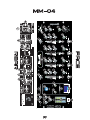 3
3
-
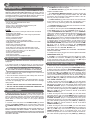 4
4
-
 5
5
-
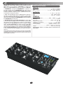 6
6
-
 7
7
-
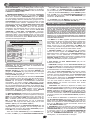 8
8
-
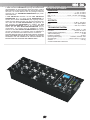 9
9
-
 10
10
-
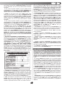 11
11
-
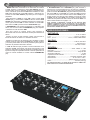 12
12
-
 13
13
-
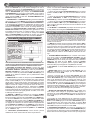 14
14
-
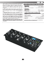 15
15
-
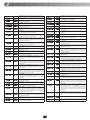 16
16
-
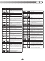 17
17
-
 18
18
-
 19
19
-
 20
20


Gemini MM-04 Bedienungsanleitung
- Kategorie
- Audiomischer
- Typ
- Bedienungsanleitung
in anderen Sprachen
- English: Gemini MM-04 Owner's manual
- français: Gemini MM-04 Le manuel du propriétaire
- español: Gemini MM-04 El manual del propietario
Verwandte Artikel
-
Gemini PS-01 Benutzerhandbuch
-
-
-
-
-
-
-
-
-