
AT-TS-13
Installation and operating instructions
Montage- und Bedienungsanleitung
Instructions d’assemblage et de service
Raychem

2 | nVent.com
GB
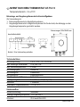
NVENT RAYCHEM THERMOSTAT AT-TS-13
Temperature range –5 à +15°C
Control and ambient thermostat in a plastic enclosure
For use as:
1. Control thermostat in trace heating systems
2. Ambient thermostat in trace heating systems for frost protection
R
122
120
Jumper 1-5 included in scope of suppl
y
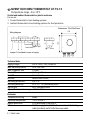
Wiring diagram
Dimensions: 122x120x55 mm
Sensor
Heater/Relay
bl
81
LN
23 45 69
_
+ br
ϑ
ϑ
Technical data:
Supply voltage 230 V +10%/–15%, 50/60 Hz
Max. switching current 16 A, 250 V AC
Max. conductor size 2.5 mm
2
Green LED Heating cable on
Red LED Sensor break
Red LED Sensor short circuit
Switching differential 0,6 –1 K
Switching accuracy +5°C: +/– 1 K (calibration point)
Switch type SPST (normally open)
Adjustable temperature range –5°C à +15°C
Enclosure:
Temperature setting inside
Exposure temperature –20°C to +50°C
Ingress protection IP 65 according to EN 60529
Entries M 20 for supply cable, M 25 for the connection to the heating
cable (not direct) and M 16 for the sensor cable.

nVent.com | 3
Weight (without sensor) +/– 440 g
Material ABS
Lid fixing Zn AL 4 Cu1 nickel plated quick release screws in four places
Mounting nVent RAYCHEM support bracket JB-SB-01 or wall mounting
Temperature sensor
Type PTC KTY 83-110
sensor cable 3 m
Diameter sensor cable ± 5,5 mm
Diameter sensor head 6,5 mm
Max. exposure temperature
sensor cable 80°C
Sensor characteristic
Temperature (°C) Resistance (Ohm)
– 5 787
0 820
+ 5 854
+ 10 889
+ 15 925
The sensor cable can be extended up to 100 m when a cross section of 1.5 mm
2
is used.
If sensor cable will be extended no live cables should be laid in parallel to avoid inductive
interferences.
Installation of heating cable
Follow the „General installation instructions for self-regulating heating cables”. Max.
circuit lengths are nVent RAYCHEM WinterGard FS-A-2X: 150m, FS-B-2X: 105m, FS-C-2X:
90m, FroStop Green: 100m, FroStop Black: 80m. Use a contactor for longer heating circuit
lengths.
Functional description
When the temperature exceeds the adjusted setpoint value, the switching contact opens
and switches the heating cable off.
When the temperature falls below the setpoint value, the switching contact closes. The
integrated green LED display lights up to indicate that the heating cable is switched on. In the
event of sensor break or shortcircuit, the switching contact closes. In the event of loss a power
supply, the switching contact opens. The integrated red LED display lights up to indicate that
there is a defect.
TC RU C-BE.БЛ08.B.01634

4 | nVent.com
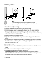
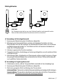
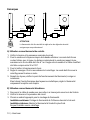
Installation guidelines
90 - 120°
R
230 V AC
R
230 V AC
A. Control thermostat (line sensing)
1. Check the voltage and the rated power of the switching circuit
2. Attach temperature sensor to the pipe with adhesive tape. The sensor should rest
firmlyagainst the pipe without intermediate space. The minimum distance of the
sensor from fittings and the pipe end is 1 m. The angle of the pipe between the heating
cable and the sensor should be 90-120°.
3. Mount the housing in the required position.
4. Adjust the temperature. Finish the wiring and insulation. Only operate with insulated
sensor.
5. Fill the pipes, check the operating points with a thermometer and correct if necessary.
Due to the low heat conductivity of non-metallic pipes, adjust the thermostat operating
point only when the pipe is full.
B. Ambient thermostat
1. Shorten the sensor cable so that the temperature sensor is located within the screwed
gland.
2. Check the voltage and the rated power of the switching circuit.
3. Select a suitable place for the thermostat installation:
Outdoor installation: Mount the thermostat away from direct sunlight and wind.
Indoor installation: Mount the thermostat at a place where the lowest temperature can
be expected. Do not install the thermostat under the insulation.
NOTE
The thermostat should be installed and adjusted by qualified
personnel only. The relevant safety regulations must be observed.

nVent.com | 5
D
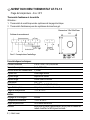
NVENT RAYCHEM THERMOSTAT AT-TS-13
Temperaturbereich –5 à +15°C
Rohranlege- und Umgebungsthermostat in Kunststoffgehäuse
Zur Verwendung als:
1. Rohranlegethermostat in Begleitheizsystemen.
2. Umgebungsthermostat in Begleitheizsystemen für Frostschutz, die abhängig von der
Umgebungstemperatur geschaltet werden.
R
122
120
Brücke 1-5 im Lieferumfang enthalten
Anschlußschaltbild
Abmessungen 122x120x55 mm
Fühler
Heizer/Schütz
bl
8
LN
3456 9
_
+br
ϑ
ϑ
123
Technische Daten:
Betriebsspannung 230 V +10%/–15%, 50/60 Hz
max. zulässiger Schaltstrom 16 A, 250 V AC
max. Anschlußquerschnitt 2,5 mm
2
LED-Anzeige grün Heizen ein
LED-Anzeige rot Fühlerbruch
LED-Anzeige rot Fühlerkurzschluß
Schalttemperatur-Differenz 0,6 bis 1 K
Schaltgenauigkeit bei +5°C: +/– 1 K (Eichpunkt)
Kontaktart 1 Schließer
einstellbarer Temperaturbereich –5°C à +15°C
Gehäuseaufbau:
Sollwerteinstellung Innenskala
zulässige Umgebungstemperatur –20°C bis +50°C
Schutzart IP 65 nach EN 60529

6 | nVent.com
Kabeleinführung M 20 für das Stromversorgung-skabel, M 25 für das erbind
ungskabel zum Heizband und M 16 für das Fühlerkabel
Gewicht (ohne Fühler) +/– 440 g
Gehäusematerial ABS
Deckel-Befestigungsschrauben GD-Zn AL 4 Cu1 galvanisch vernickelt; 1/4-Dreh-Schnellverschluß
Montagemethode Mittels RAYCHEM Befestigungs-winkel JB-SB-01 oder
Wand montage
Temperaturfühler
Bauart PTC KTY 83-110
Fühler-Kabellänge 3 m
Durchmesser des Fühlerkabels ± 5,5 mm
Durchmesser des Fühlers 6,5 mm
Max. zul. Umgebungstemperatur
des Fühlerkabels 80°C
Fühlerkenndaten
Temperatur (°C) Widerstandswert (Ohm)
– 5 787
0 820
+ 5 854
+ 10 889
+ 15 925
Das Fühlerkabel kann mit einem Querschnitt von 1,5 mm
2
bis auf 100 m verlängert
werden. Bei verlängerter Fühlerleitung sollte zur Vermeidung von Störeinflüssen eine
Parallelverlegung von Lastleistungen vermieden werden.
Heizbandmontage
Beachten Sie die „Allgemeine Montagehinweise für selbstregelnde Heizbänder“. Die max.
Heizbandlängen sind WinterGard FS-A-2X: 150m, FS-B-2X: 105m, FS-C-2X: 90m, FroStop
Green: 100m, FroStop Black: 80m. Bei größeren Heizbandlängen ist ein Schütz notwendig.
Funktionsbeschreibung
Übersteigt die Temperatur den eingestellten Sollwert, öffnet der Schaltkontakt und schaltet das
Heizband aus. Unterschreitet die Temperatur den Sollwert, schließt der Schaltkontakt. Durch das
Aufleuchten der eingebauten grünen Kontrollampe wird angezeigt, daß das Heizband eingeschaltet
ist. Bei Netzausfall öffnet der Schaltkontakt. Bei Fühlerunterbrechung oder Kurzschluß des
Fühlers schließt der Schaltkontakt. Das Heizband wird eingeschaltet. Durch Aufleuchten der roten
Kontrollampen Fühlerbruch oder Fühlerkurzschluß wird angezeigt, daß eine Störung vorhanden ist.
TC RU C-BE.БЛ08.B.01634

nVent.com | 7
Montagehinweise
90 - 120°
R
230 V AC
R
230 V AC
A) Verwendung als Rohranlegethermostat
1. Spannung und Nennleistung des Schaltkreises überprüfen.
2. Befestigung des Temperaturfühlers am Rohr mit Klebeband. Der Fühler soll ohne
Zwischenraum fest am Rohr anliegen. Der Mindestabstand des Fühlers von Armaturen
und Rohrleitungsende beträgt 1 m. Der Winkel am Rohr soll zwischen Heizband und
Fühler 90–120 Grad betragen.
3. Gehäuse in gewünschter Position montieren.
4. Temperatur einstellen, Verdrahtung und Isolierung fertigstellen, nur mit isoliertem Fühler
in Betrieb nehmen.
5. Rohrleitungen füllen, Schaltpunkte mit Thermometer prüfen und ggf. korrigieren. Wegen
der geringen Wärmeleitfähigkeit bei nichtmetallischen Rohren Thermostatschaltpunkt
nur in gefülltem Zustand einstellen.
B) Verwendung als Umgebungsthermostat
1. Fühlerkabel so kürzen, daß der Temperaturfühler innerhalb der Verschraubung liegt.
2. Spannung und Nennleistung des Schaltkreises überprüfen.
3. Wahl einer geeigneten Stelle zur Montage des Thermostaten.
Außeninstallation: Thermostat vor direkter Sonneneinstrahlung und windgeschützt anbringen.
Inneninstallation: Thermostat in dem Bereich montieren, der die tiefsten Temperaturen
erwarten läßt. Thermostat nicht unter der Isolierung installieren.
ACHTUNG!
Der Temperaturregler darf nur von einer Fachkraft installiert und eingestellt werden.
Dabei sind die bestehenenden Sicherheitsvorschriften zu beachten.

8 | nVent.com
F
NVENT RAYCHEM THERMOSTAT AT-TS-13
Plage de température –5 à +15°C
Thermostat d’ambiance et de contrôle
Utilisation :
1. Thermostat de contrôle pour des systèmes de traçage électrique.
2. Thermostat d’ambiance pour des systèmes de mise hors gel.
R
122
120
Pont 1-5 compris dans l’emballage
Schéma de raccordement
Dimensions 122x120x55 mm
Sonde
Ruban/Relais
bl
81
LN
23 45 69
_
+br
ϑ
ϑ
Caractéristiques techniques:
Tension nominale 230 V +10%/–15%, 50/60 Hz
Pouvoir de coupure 16 A, 250 V AC
Section max. des conducteurs 2,5 mm
2
Voyant vert Chauffage allumé
Voyant rouge Rupture de sonde
Voyant rouge Sonde court-circuitée
Différentiel 0,6 – 1 K
Précision à +5°C: +/– 1 K (Calibration)
Type d’interupteur Unipolare, normalement ouvert
Plage de température –5°C à +15°C
Boîtier:
Réglage de la consigne interne
Température ambiante –20°C à +50°C
Degré de protection IP 65 selon EN 60529
Entrées M20 pour le cable d’alimentation, M 25 pour la liasion au
ruban chauffant et M16 pour la sonde.

nVent.com | 9
Poids (sans sonde) env. 440 g
Matériau ABS
Vis de fixation GD-Zn AL 4 Cu1 nickelées 1/4 de tour
Montage Sur support nVent RAYCHEM JB-SB-01 ou montage mural
Sonde
Type PTC KTY 83-110
Longueur du câble 3 m
Diamètre du câble ± 5,5 mm
Diamètre de la sonde 6,5 mm
Température d’expostion
maximale pour le câble
de la sonde 80°C
Caractéristiques de la sonde
Témperature (°C) Résistance (Ohm)
– 5 787
0 820
+ 5 854
+ 10 889
+ 15 925
Le câble de la sonde peut être prolongé jusqu’a 100 m avec un câble de section 1,5 mm
2
.
En cas de prolongationdu câble de la sonde, ne pas poser en parallèle des câbles de
puissance afin d’eviter des perturbations.
Installation du ruban chauffant
L’utilisateur doit se conformer aux ”Instructions générales d’installation des rubans
chauffants autorégulants”. Les longueurs max. sont WinterGard FS-A-2X: 150m, FS-B-2X:
105m, FS-C-2X: 90m, FroStop Green: 100m, FroStop Black: 80m. Pour des longueurs
supérieures, utilisez un contacteur.
Fonctionnement
Si la température ambiante dépasse la valeur de consigne, le contact de sortie s’ouvre et
coupe le chauffage. Si la température ambiante est en dessous de la valeur de consigne,
le contact se ferme. La LED verte indique que le chauffage est activé. En cas de coupure
de courant, le contact s’ouvre. Lorsqu’il y a une coupure ou un court-circuit au niveau de la
sonde, le contact est fermé et la chauffage allumé. Une LED rouge indique la coupure ou le
court-circuit de la sonde.
TC RU C-BE.БЛ08.B.01634

10 | nVent.com
Remarques
90 - 120°
R
230 V AC
R
230 V AC
A) Utilisation comme thermostat de contrôle
1. Vérifer le tension et la puissance nominale du circuit.
2. Fixer la sonde sur le tuyau au moyen de la bande adhésive. La sonde doit être en
contact intime avec le tuyau. La distance minimale de la sonde par rapport à une
armature ou la fin du câble doit être d’1 m. L’angle entre la sonde et le câble chauffant
doit être compris entre 90 et 120°.
3. Fixer le boîtier à l’emplacement choisi.
4. Regler le consigne. Finir le raccordement et calorifuger. La sonde doit être sous le
calorifuge avant la mise en route.
5. Remplir les tuyaux, vérifier le point de fonctionnement du thermostat, corriger si
nécessaire.
Etant donné l’inertie thermique des tuyaux non métalliques, régler le thermostat
uniquement lorsqu’ils sont remplis.
B) Utilisation comme thermostat d’ambiance
1. Raccourcir le câble de sonde pour que celle-ci se trouve juste sous la vis de l’entrée.
2. Vérifier la tension et la puissance du circuit.
3. Choisir un endroit approprié pour le montage du thermostat.
Installation extérieure: Protéger le thermostat de l’influence du soleil et du vent.
Installation intérieure: Monter le thermostat à l’endroit le plus froid.
Ne pas l’installer sous le calorifuge.
ATTENTION!
Le thermostat doit être installé et reglé selon les rêgles de sécurité
envigueur par un professionnel.

nVent.com | 11

©2018 nVent. All nVent marks and logos are owned or licensed by nVent Services GmbH or its aliates. All other trademarks are the
property of their respective owners. nVent reserves the right to change specications without notice.
Raychem-IM-INST216-ATTS13-ML-1811
nVent.com
België / Belgique
Tel. +32 16 21 35 02
Fax +32 16 21 36 04
Bulgaria
Tel. +359 5686 6886
Fax +359 5686 6886
Česká Republika
Tel. +420 602 232 969
Denmark
Tel. +45 70 11 04 00
Deutschland
Tel. 0800 1818205
Fax 0800 1818204
España
Tel. +34 911 59 30 60
Fax +34 900 98 32 64
France
Tél. 0800 906045
Fax 0800 906003
Hrvatska
Tel. +385 1 605 01 88
Fax +385 1 605 01 88
Italia
Tel. +39 02 577 61 51
Fax +39 02 577 61 55 28
Lietuva/Latvija/Eesti
Tel. +370 5 2136633
Fax +370 5 2330084
Magyarország
Tel. +36 1 253 7617
Fax +36 1 253 7618
Nederland
Tel. 0800 0224978
Fax 0800 0224993
Norge
Tel. +47 66 81 79 90
Österreich
Tel. 0800 29 74 10
Fax 0800 29 74 09
Polska
Tel. +48 22 331 29 50
Fax +48 22 331 29 51
Republic of Kazakhstan
Tel. +7 7122 32 09 68
Fax +7 7122 32 55 54
Россия
Тел. +7 495 926 18 85
Факс +97 495 926 18 86
Serbia and Montenegro
Tel. +381 230 401 770
Fax +381 230 401 770
Schweiz / Suisse
Tel. +41 (41) 766 30 80
Fax +41 (41) 766 30 81
Suomi
Puh. 0800 11 67 99
Sverige
Tel. +46 31 335 58 00
Türkiye
Tel. +90 560 977 6467
Fax +32 16 21 36 04
United Kingdom
Tel. 0800 969 013
Fax 0800 968 624
-
 1
1
-
 2
2
-
 3
3
-
 4
4
-
 5
5
-
 6
6
-
 7
7
-
 8
8
-
 9
9
-
 10
10
-
 11
11
-
 12
12


Raychem AT-TS-13 Installationsanleitung
- Typ
- Installationsanleitung
- Dieses Handbuch eignet sich auch für
in anderen Sprachen
- English: Raychem AT-TS-13 Installation guide
- français: Raychem AT-TS-13 Guide d'installation
Verwandte Artikel
-
Raychem Moni-PT100-NH Installationsanleitung
-
-
-
-
-
-
Raychem Raychem ETS-05-H1-J Installationsanleitung
-
-
-
Raychem Raystat-reglering-11-DIN Installationsanleitung