
CĘGI ELASTYCZNE
F-xA ● F-xA1 ● F-xA6
INSTRUKCJA OBSŁUGI
Wersja 1.03 25.05.2023
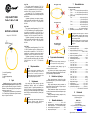
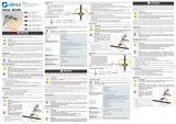
1 – cewka Rogowskiego
2 – zapięcie
3 – przewód połączeniowy
4 – wtyk 1 Opis
Strzałka umieszczona na zapięciu cęgów wska-
zuje kierunek przepływu prądu. Uznaje się, że prąd
płynie w dodatnim kierunku jeśli płynie od źródła do
odbiornika. Taka orientacja cęgów jest wymagana do
poprawnego pomiaru mocy.
Sygnał wyjściowy wyprowadzony jest przewodem
2,5 m zakończonym odpowiednim wtykiem dostoso-
wanym do gniazda w mierniku.
Cęgi F-xA
Cęgi giętkie (cewka Rogowskiego) F-1A, F-2A
i F-3A przeznaczone są do pomiaru prądów prze-
miennych o częstotliwościach od 40 Hz do 20 kHz w
zakresie do 3000 A (szczytowo 10 kA dla 50 Hz).
Cęgi giętkie F-1A, F-2A i F-3A różnią się między
sobą jedynie obwodem cewki. Parametry elektryczne
są takie same.
Sygnałem wyjściowym jest napięcie proporcjo-
nalne do pochodnej mierzonego prądu przy czułości
38,83 mV/1000 A dla 50 Hz i 46,6 mV/1000 A
dla 60 Hz.
Cęgi F-xA1
Cęgi giętkie (cewka Rogowskiego) F-1A1, F-2A1
i F-3A1 są odmianami cęgów o dwukrotnie zwiększo-
nej czułości w porównaniu z F-1A/F-2A/F-3A, co
przekłada się na dwukrotnie mniejszy zakres pomia-
rowy prądu – do 1500 A (szczytowo 5 kA dla 50 Hz).
Sygnałem wyjściowym jest napięcie proporcjo-
nalne do pochodnej mierzonego prądu przy czułości
77,66 mV/1000 A dla 50 Hz i 93,19 mV/1000 A
dla 60 Hz.
Cęgi F-xA6
Cęgi giętkie (cewka Rogowskiego) F-1A6, F-2A6
i F-3A6 są odmianami cęgów o dwukrotnie zmniej-
szonej czułości w porównaniu z F-1A/F-2A/F-3A, co
przekłada się na dwukrotnie większy zakres pomia-
rowy prądu – do 6000 A (szczytowo 20 kA dla 50 Hz).
Sygnałem wyjściowym jest napięcie proporcjo-
nalne do pochodnej mierzonego prądu przy czułości
19,415 mV/1000 A dla 50 Hz i 23,3 mV/1000 A
dla 60 Hz.
2 Bezpieczeństwo
UWAGA!
Nie wolno używać cęgów z nieizolowanymi prze-
wodnikami o potencjale wyższym niż 1000 V w
stosunku do ziemi i w instalacjach o kategorii po-
miarowej wyższej niż III oraz w instalacjach o ka-
tegorii IV i potencjale wyższym niż 600 V.
3 Użytkowanie
Aby mierzyć prąd, należy otworzyć cęgi lekko
przekręcając zapięcie, objąć nimi przewodnik
z płynącym prądem i zgrubnie wyśrodkować prze-
wodnik w stosunku do pętli cęgów. Następnie za-
mknąć cęgi, ponownie przekręcając zapięcie. Należy
zwrócić uwagę na kierunek strzałki, aby uniknąć błę-
du pomiaru mocy.
UWAGA!
Należy przestrzegać wskazówek dotyczących me-
chanicznych ograniczeń cewek. Mechaniczne
uszkodzenia cęgów nie podlegają gwarancji.
Nie ciągnąć na siłę
Nie zginać na siłę
Nie przechowywać
w stanie zgiętym
4 Czyszczenie i konserwacja
UWAGA!
Należy stosować jedynie metody konserwacji po-
dane przez producenta w niniejszej instrukcji.
Przed czyszczeniem należy odłączyć cęgi od
mierzonego obwodu i miernika.
Cęgi można czyścić miękką, wilgotną szmatką
używając ogólnie dostępnych detergentów. Nie nale-
ży używać żadnych rozpuszczalników.
5 Rozbiórka i utylizacja
Zużyty sprzęt elektryczny i elektroniczny należy
gromadzić selektywnie, tj. nie umieszczać z odpada-
mi innego rodzaju.
Zużyty sprzęt elektryczny należy przekazać do
punktu zbiórki zgodnie z Ustawą o zużytym sprzęcie
elektrycznym i elektronicznym.
Przed przekazaniem sprzętu do punktu zbiórki
nie należy samodzielnie demontować żadnych części
z tego sprzętu.
Należy przestrzegać lokalnych przepisów doty-
czących wyrzucania opakowań.
6 Warunki odniesienia
a) temperatura .................................................... +18°C…+22°C
b) pozycja przewodnika ..... wyśrodkowany względem pętli cęgów
c) stałe pole magnetyczne ........ <40 A/m (ziemskie pole magn.)
d) zmienne zewnętrzne pole magnetyczne .......................... brak
e) zewnętrzne pole elektryczne ............................................ brak
7 Dane techniczne
Podstawowe dane techniczne
a) zakres pomiarowy
▪ F-xA .............. 1 A…3000 A (10000 A szczytowo dla 50 Hz)
▪ F-xA1 .............. 1 A…1500 A (5000 A szczytowo dla 50 Hz)
▪ F-xA6 ............ 1 A…6000 A (20000 A szczytowo dla 50 Hz)
b) sygnał wyjściowy
▪ F-xA ............................................. 38,83 mV/1000 A (50 Hz)
......................................................... 46,6 mV/1000 A (60 Hz)
▪ F-xA1 ........................................... 77,66 mV/1000 A (50 Hz)
........................................................ 93,19 mV/1000 A (60 Hz)
▪ F-xA6 ......................................... 19,415 mV/1000 A (50 Hz)
............................................................ 23,3 mV/1000 (60 Hz)
c) dokładność ...............................±1% w zakresie pomiarowym
d) błąd dodatkowy od położenia przewodnika .......... ±1% maks.
W przypadku stosowania cęgów z miernikiem
SONEL dokładność całkowita układu pomiaro-
wego miernik + cęgi podawana jest w instrukcji
obsługi danego miernika.
Dokładność cęgów podana w niniejszej instrukcji
nie jest sumą dokładności miernika i dokładno-
ści cęgów.
Pozostałe dane techniczne
a) rodzaj izolacji wg IEC 61010-1 ................................ podwójna
b) kategoria pomiarowa wg IEC 61010-2-030 ............................
..................................................................III 1000 V, IV 600 V
c) stopień zanieczyszczenia .................................................... 2
d) stopień ochrony obudowy wg IEC 60529 ........................ IP67
e) średnica cewki pomiarowej ........................................ 8,4 mm
f) średnica zapięcia (maksymalna) ................................. 36 mm
g) obwód cewki
▪ F-1A, F-1A1, F-1A6 .................................................. 120 cm
▪ F-2A, F-2A1, F-2A6 ................................................... 80 cm
▪ F-3A, F-3A1, F-3A6 ................................................... 45 cm
h) wewnętrzna średnica cęgów po zapięciu
▪ F-1A, F-1A1, F-1A6 .................................................... 38 cm
▪ F-2A, F-2A1, F-2A6 ................................................... 25 cm
▪ F-3A, F-3A1, F-3A6 ................................................... 14 cm
i) masa
▪ F-1A, F-1A1, F-1A6 .............................................. ok. 200 g
▪ F-2A, F-2A1, F-2A6 ............................................... ok. 170 g
▪ F-3A, F-3A1, F-3A6 .............................................. ok. 140 g
j) długość przewodu cęgów .............................................. 2,5 m
k) temperatura pracy ........................................... -30°C…+80°C
l) temperatura przechowywania ......................... -40°C…+80°C
m) wyrób spełnia wymagania norm ....................... IEC 61010-1,
........................................... IEC 61010-031, IEC 61010-2-032
8 Producent
Prowadzącym serwis gwarancyjny
i pogwarancyjny jest:
SONEL S.A.
ul. Wokulskiego 11
58-100 Świdnica
tel. (74) 858 38 00 (Biuro Obsługi Klienta)
e-mail: bok@sonel.pl
internet: www.sonel.pl
Wyprodukowano we Włoszech dla SONEL S.A.

FLEXIBLE COIL
F-xA ● F-xA1 ● F-xA6
USER MANUAL
Version 1.03 25.05.2023
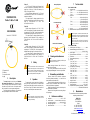
1 – Rogowski coil
2 – fastener
3 – connection cable
4 – plug 1 Description
The arrow located on the closing unit indicates
the current flow direction. It is assumed that the
current is flowing in the positive direction if it is flowing
from the source to the receiver. Such probe orienta-
tion is required for a correct power measurement.
The output signal is supplied by a 2.5-meter lead
with a pin adapted for the socket in the meter.
F-xA coil
F-1A, F-2A and F-3 flexible coils (Rogowski coil)
are used to measure the alternating current in the
range from 40 Hz up to 20 kHz and current up to
3000 A (10 kA peak at 50 Hz)
The only difference between the F-1A, F-2A and
F-3A flexible coils is the coil size. The electrical pa-
rameters are identical.
The output signal if voltage proportional to the
derivative of the measured current, with the sensitivity
equal to 38.83 mV/1000 A for 50 Hz and
46.6 mV/1000 A for 60 Hz.
F-xA1 coil
Flexible clamps (Rogowski coil) F-1A1, F-2A1
and F-3A1 are probes of a double-increased sensitivi-
ty comparing to F-1A/F-2A/F-3A, which translates into
halved measuring range for current up to 1500 A.
The output signal is voltage proportional to the
measured current derivative at the sensitivity of
77.66 mV/1000 A for 50 Hz and 93.19 mV/1000 A
for 60 Hz.
F-xA6 coil
Flexible probes (Rogowski coil) F-1A6, F-2A6
and F-3A6 are clamps of a double-reduced sensitivity
comparing to F-1A/F-2A/F-3A, which translates into
doubled measuring range for current up to 6000 A.
The output signal is voltage proportional to the
measured current derivative at the sensitivity of
19.415 mV/1000 A for 50 Hz and 23.3 mV/1000 A
for 60 Hz.
2 Safety
NOTE!
Do not use non-insulated coils for conductors with
a potential exceeding 1000 V with respect to the
ground, in systems with the measurement catego-
ry higher than III and systems of measurement
category IV with potential exceeding 600 V.
3 Operation
To measure the current, open the coil slightly by
turning the clasp, clamp them on the conductor with
flowing current and roughly center the conductor rela-
tive to the coil loop. Pay attention to the direction of
the arrow, to avoid the power measurement error.
NOTE!
Follow the instructions for mechanical limitations
of the coils. Mechanical damage to the coil is not
covered by the warranty.
Do not pull by force
Do not bend forcibly
Do not pack in a bent state
4 Cleaning and maintenance
NOTE!
Apply only maintenance methods specified by the
manufacturer in this manual.
Before cleaning, disconnect the coil from the
tested circuit and the meter.
The coil may be cleaned with a soft, damp cloth
using all-purpose detergents. Do not use any solvents.
5 Dismantling and utilisation
Worn-out electric and electronic equipment
should be gathered selectively, i.e. it must not be
placed with waste of another kind.
Worn-out electric equipment should be sent to a
collection point in accordance with the law of waste
electrical and electronic equipment.
Before the equipment is sent to a collection point,
do not dismantle any elements.
Observe the local regulations concerning dispos-
al of packages.
6 Reference conditions
a) temperature ................................................... +18°C …+22°C
b) conductor position ........... centered in relation to the coil loop
c) continuous magnetic field ...................... <40 A/m (earth field)
d) alternating magnetic field ................................................ none
e) external electric field ........................................................ none
7 Technical data
Basic technical data
a) measuring range
▪ F-xA ......................... 1 A…3000 A (10000 A peak at 50 Hz)
▪ F-xA1 ......................... 1 A…1500 A (5000 A peak at 50 Hz)
▪ F-xA6 ....................... 1 A…6000 A (20000 A peak at 50 Hz)
b) output level
▪ F-xA ............................................. 38.83 mV/1000 A (50 Hz)
......................................................... 46.6 mV/1000 A (60 Hz)
▪ F-xA1 ........................................... 77.66 mV/1000 A (50 Hz)
........................................................ 93.19 mV/1000 A (60 Hz)
▪ F-xA6 ......................................... 19.415 mV/1000 A (50 Hz)
............................................................ 23.3 mV/1000 (60 Hz)
c) accuracy .................................... ±1% in the measuring range
d) additional error due to the position of the conductor . ±1% max.
When using the coil with a SONEL meter, total
measurement accuracy of the measuring system
of the meter and coil is specified in the manual
of a given meter.
The accuracy of the coil given in this manual is
not the sum of the accuracy of the meter and
accuracy of the coil.
Other technical data
a) insulation type acc. to IEC 61010-1 ............................. double
b) measurement category acc. to IEC 61010-2-030 ......................
...............................................................................III 1000 V, IV 600 V
c) pollution degree..................................................................... 2
d) ingress protection acc. to IEC 60529 ............................... IP67
e) coil diameter ............................................................... 8.4 mm
f) fastener diameter (maximum) ...................................... 36 mm
g) coil circuit
▪ F-1A, F-1A1, F-1A6 .................................................. 120 cm
▪ F-2A, F-2A1, F-2A6 ................................................... 80 cm
▪ F-3A, F-3A1, F-3A6 ................................................... 45 cm
h) inner diameter of coil after closing
▪ F-1A, F-1A1, F-1A6 .................................................... 38 cm
▪ F-2A, F-2A1, F-2A6 ................................................... 25 cm
▪ F-3A, F-3A1, F-3A6 ................................................... 14 cm
i) weight
▪ F-1A, F-1A1, F-1A6 .............................................. ca. 200 g
▪ F-2A, F-2A1, F-2A6 ............................................... ca. 170 g
▪ F-3A, F-3A1, F-3A6 .............................................. ca. 140 g
j) length of coil cable ......................................................... 2.5 m
k) operating temperature ..................................... -30°C…+80°C
l) storage temperature ........................................ -40°C…+80°C
m) the product meets requirements of standards ...... IEC 61010-1
............................................................. IEC 61010-031, IEC 61010-2-032
8 Manufacturer
The manufacturer, which also provides guarantee
and post-guarantee services:
SONEL S.A.
Wokulskiego 11
58-100 Świdnica
Poland
tel. +48 74 858 38 60
fax +48 74 858 38 09
e-mail: export@sonel.pl
web page: www.sonel.pl
Manufactured in Italy for SONEL S.A.

PINZA FLEXIBLE
F-xA ● F-xA1 ● F-xA6
MANUAL DE USO
Versión 1.03 25.05.2023
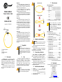
1 – bobina de Rogowski
2 – cierre
3 – cable de conexión
4 – clavija
1 Descripción
La flecha situada en el cierre de las mordazas
indica la dirección de flujo de corriente. Se
considera que la corriente fluye en la dirección
positiva si fluye desde la fuente hasta el receptor. Se
requiere esta orientación para medir correctamente
la potencia.
La señal de salida es suministrada con el cable
de 2,5 m con una clavija adaptada a la toma en
el medidor.
Pinza F-xA
La pinza flexible (bobina de Rogowski) F-1A,
F-2A y F-3A está diseñada para medir las corrientes
alternas de 40 Hz a 20 kHz en el rango de hasta
3000 A (10 kA en cresta para 50 Hz).
Las pinzas flexibles F-1A, F-2A y F-3A se difieren
sólo por la circunferencia de la bobina. Los
parámetros eléctricos son los mismos.
La señal de salida es una tensión proporcional a
la derivada de la corriente medida con la sensibilidad
de 38,83 mV/1000 A para 50 Hz y 46,6 mV/1000 A
para 60 Hz.
Pinza F-xA1
La pinza flexible (bobina de Rogowski) F-1A1,
F-2A1 y F-3A1 son variantes de la pinza de la
sensibilidad aumentada dos veces en comparación
con F-1A/F-2A/F-3A, lo que se traduce en el rango de
la corriente dos veces más pequeño - hasta 1500 A.
La señal de salida es una tensión proporcional a
la derivada de la corriente medida con la sensibilidad
de 77,66 mV/1000 A para 50 Hz y 93,19 mV/1000 A
para 60 Hz.
Pinza F-xA6
La pinza flexible (bobina de Rogowski) F-1A6,
F-2A6 y F-3A6 son variantes de la pinza de la
sensibilidad reducida dos veces en comparación con
F-1A/F-2A/F-3A, lo que se traduce en el rango de la
corriente dos veces más grande - hasta 6000 A.
La señal de salida es una tensión proporcional a
la derivada de la corriente medida con la sensibilidad
de 19,415 mV/1000 A para 50 Hz y 23,3 mV/1000 A
para 60 Hz.
2 Seguridad
¡ATENCIÓN!
No está permitido utilizar el dispositivo en los
conductores no aislados, con un potencial mayor
a 1000 V respecto a tierra y en las instalaciones
con la categoría de medición superior a III y en las
instalaciones de la categoría IV y con un potencial
mayor a 600 V.
3 Uso
Para medir la corriente, abrir las mordazas de la
pinza girando ligeramente el cierre, rodear un
conductor con la corriente y centrar el conductor
aproximadamente en relación con el bucle de la
pinza. Luego cerrar la pinza girando el cierre
nuevamente. Prestar atención a la dirección de la
flecha para evitar errores de medición de potencia.
¡ATENCIÓN!
Seguir las instrucciones para las limitaciones
mecánicas de las bobinas. Los daños mecánicos
a la pinza no están cubiertos por la garantía.
No tirar a la fuerza
No doblar a la fuerza
No guardar
doblado
4 Limpieza y mantenimiento
¡ATENCIÓN!
Utilizar únicamente el método de conservación
proporcionado por el fabricante en este manual.
Antes de limpiar, desconectar la pinza del circuito
medido y del medidor.
La pinza puede ser limpiada con un paño suave
y humedecido con detergentes comúnmente
utilizados. No usar ningún disolvente.
5 Desmontaje y utilización
Los residuos de aparatos eléctricos
y electrónicos deben ser recogidos por separado, es
decir, no se depositan con los residuos de otro tipo.
El dispositivo electrónico debe ser llevado a un
punto de recogida conforme con la Ley de residuos
de aparatos eléctricos y electrónicos.
Antes de llevar el equipo a un punto de recogida
no se debe desarmar ninguna parte del equipo.
Hay que seguir las normativas locales en cuanto
a la eliminación de envases.
6 Condiciones de referencia
a) temperatura ................................................... +18°C …+22°C
b) posición del conductor ....... centrado respecto el bucle de pinza
c) campo magnético constante ...................................................
................................ <40 A/m (campo magnético de la tierra)
d) campo magnético externo alterno ...................................... sin
e) campo eléctrico externo ..................................................... sin
7 Datos técnicos
Datos técnicos basicos
a) rango de medición
▪ F-xA ............. 1 A…3000 A (10000 A en cresta para 50 Hz)
▪ F-xA1 ............. 1 A…1500 A (5000 A en cresta para 50 Hz)
▪ F-xA6 ........... 1 A…6000 A (20000 A en cresta para 50 Hz)
b) señal de salida
▪ F-xA ............................................. 38,83 mV/1000 A (50 Hz)
......................................................... 46,6 mV/1000 A (60 Hz)
▪ F-xA1 ........................................... 77,66 mV/1000 A (50 Hz)
........................................................ 93,19 mV/1000 A (60 Hz)
▪ F-xA6 ......................................... 19,415 mV/1000 A (50 Hz)
............................................................ 23,3 mV/1000 (60 Hz)
c) precisión .................................. ±1% en el rango de medición
d) error adicional de la posición del conductor ........... ±1% máx.
Cuando se utilizan pinzas con el medidor
SONEL, la precisión total del sistema de
medición se especifica en el manual de
instrucciones del medidor dado.
La precisión de la pinza indicada en este
manual no es la suma de la precisión del
medidor y la precisión de la pinza.
Otros datos técnicos
a) tipo de aislamiento según IEC 61010-1......................... doble
b) categoría de medición según IEC 61010-2-030 ........................
...............................................................................III 1000 V, IV 600 V
c) grado de contaminación........................................................ 2
d) grado de protección según IEC 60529 ............................ IP67
e) diámetro de bobina .................................................... 8,4 mm
f) diámetro del bloque de conexión de bobina ................ 36 mm
g) circunferencia de bobina
▪ F-1A, F-1A1, F-1A6 .................................................. 120 cm
▪ F-2A, F-2A1, F-2A6 ................................................... 80 cm
▪ F-3A, F-3A1, F-3A6 ................................................... 45 cm
h) diámetro interior de pinzas después de cierre
▪ F-1A, F-1A1, F-1A6 .................................................... 38 cm
▪ F-2A, F-2A1, F-2A6 ................................................... 25 cm
▪ F-3A, F-3A1, F-3A6 ................................................... 14 cm
i) peso
▪ F-1A, F-1A1, F-1A6 .............................................. ca. 200 g
▪ F-2A, F-2A1, F-2A6 ............................................... ca. 170 g
▪ F-3A, F-3A1, F-3A6 .............................................. ca. 140 g
j) longitud de cable con pinzas ......................................... 2,5 m
k) temperatura de trabajo.................................... -30°C…+80°C
l) temperatura de almacenamiento .................... -40°C…+80°C
m) el producto cumple los requisitos de las normas ...................
................................... IEC 61010-1, IEC 61010-031, IEC 61010-2-032
8 Fabricante
El fabricante del dispositivo que presta el servicio de
garantía y postgarantía es:
SONEL S.A.
Wokulskiego 11
58-100 Świdnica
Polonia
tel. +48 74 858 38 60
fax +48 74 858 38 09
E-mail: export@sonel.pl
Página web: www.sonel.pl
Fabricado en Italia para SONEL S.A.

FLEXIBLE ZANGE
F-xA ● F-xA1 ● F-xA6
BEDIENUNGSANLEITUNG
Version 1.03 25.05.2023
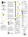
1 – Rogowski-Spule
2 – Verschluss
3 – Verbindungskabel
4 – Stecker
1 Beschreibung
Die Pfeilmarkierung auf den Zangen gibt die
Richtung des Stromflusses an. Es wird angenom-
men, dass der Stromfluss in positiver Richtung vom
Sender zum Empfänger verläuft. Diese Ausrichtung
der Stromzangen ist zur korrekten Leistungsmessung
notwendig.
Das Ausgangssignal wird über ein 2,5 m Kabel
über einen Pinstecker zum Messgerät übertragen.
Zange F-xA
Die flexiblen Zangen (Rogowski Spule) F-1A,
F-2A und F-3A werden verwendet, um AC Ströme mit
Frequenzen von 40 Hz bis zu 20 kHz im Bereich bis
zu 3000 A (Spitze 10 kA für 50 Hz).
Die Zangen F-1A, F-2A und F-3A unterscheiden
sich untereinander nur im Durchmesser der Spule.
Sämtliche elektrische Parameter sind identisch.
Die Ausgangssignalspannung ist proportional
zum gemessenen Strom mit einer Empfindlichkeit von
38,83 mV/1000 A für 50 Hz und 46,6 mV/1000 A
für 60 Hz.
Zange F-xA1
Die flexiblen Messzangen (Rogowski-Spule) F-
1A1, F-2A1 und F-3A1 sind ein Zangentyp mit dop-
pelter Empfindlichkeit im Vergleich zu F-1A/F-2A/F-
3A, was zu einem doppelt kleineren Strommessbe-
reich bis 1500 A (5 kA Spitze für 50 Hz) führt.
Die Ausgangssignalspannung ist proportional
zum gemessenen Strom mit einer Empfindlichkeit von
77,66 mV/1000 A für 50 Hz und 93,19 mV/1000 A
für 60 Hz.
Zange F-xA6
Die flexiblen Messzangen (Rogowski-Spule) F-
1A6, F-2A6 und F-3A6 sind ein Zangentyp mit dop-
pelt verminderter Empfindlichkeit im Vergleich zu F-
1A/F-2A/F-3A, was zu einem doppelt größeren
Strommessbereich bis 6000 A (2 kA Spitze für
50 Hz) führt.
Die Ausgangssignalspannung ist proportional
zum gemessenen Strom mit einer Empfindlichkeit von
19,415 mV/1000 A für 50 Hz und 23,3 mV/1000 A
für 60 Hz.
2 Sicherheit
ACHTUNG!
Die Messzange darf nicht mit nicht isolierten Lei-
tern mit dem Potential von mehr als 1000 V in Be-
zug auf die Erdung und in Installationen mit der
Messkategorie über III und Installationen mit der
Messkategorie IV und dem Potential von mehr als
600 V verwendet werden.
3 Verwendung
Backen der Messzange öffnen, dabei den Ver-
schluss leicht drehen. Den Leiter mit den Backen um-
fassen und den Leiter in Bezug auf die Schleife der
Messzange ungefähr zentrieren, um den Strom zu
messen. Dann die Messzange schließen, indem der
Verschluss erneut gedreht wird. Auf die Richtung des
Pfeils achten, um Fehler bei der Leistungsmessung
zu vermeiden.
ACHTUNG!
Anweisungen für mechanische Einschränkungen an
Spulen befolgen. Mechanische Schäden an der
Messzange sind von der Garantie ausgeschlossen.
Nicht mit Gewalt ziehen
Nicht mit Gewalt biegen
Nicht im gebogenen
Zustand lagern
4 Wartung und Reinigung
ACHTUNG!
Führen Sie nur Wartungsschritte durch wie in die-
ser Anleitung beschrieben durch.
Vor der Reinigung die Messzange vom zu mes-
senden Stromkreis und vom Messgerät trennen.
Die Messzange kann mit einem weichen, feuch-
ten Tuch und mit üblichen Reinigungsmitteln gereinigt
werden. Keine Lösungsmittel verwenden.
5 Zerlegen und Entsorgen
Ausgediente Elektronik und elektronisches Zube-
hör darf nicht zusammen mit gewöhnlichem Hausmüll
gesammelt werden, sondern muss getrennt gehal-
ten werden.
Bringen Sie diese zu den gesetzlich vorgeschrie-
benen Sammelstellen für elektrisches und elektro-
nisches Zubehör.
Zerlegen Sie die Geräte nicht in Einzelteile, bevor
Sie es zum Entsorgen bringen.
Halten Sie die vorgeschriebenen Bestimmungen
zur Entsorgung von Verpackungen ein.
6 Referenzbedingungen
a) Temperatur .................................................... +18°C …+22°C
b) Leiterposition ..........................Im Zentrum der Klemmbacken
c) Permanentes magnetisches Feld ... <40 A/m (Erdmagnetfeld)
d) Variable des externen magnetischen Feldes ................. keine
e) Externes elektrisches Feld ............................................. keine
7 Technische Daten
Grundlegende technische Daten
a) Messbereich
▪ F-xA ..................... 1 A…3000 A (Spitze 10000 A für 50 Hz)
▪ F-xA1 ..................... 1 A…1500 A (Spitze 5000 A für 50 Hz)
▪ F-xA6 ................... 1 A…6000 A (Spitze 20000 A für 50 Hz)
b) Ausgangssignal
▪ F-xA ............................................. 38,83 mV/1000 A (50 Hz)
......................................................... 46,6 mV/1000 A (60 Hz)
▪ F-xA1 ........................................... 77,66 mV/1000 A (50 Hz)
........................................................ 93,19 mV/1000 A (60 Hz)
▪ F-xA6 ......................................... 19,415 mV/1000 A (50 Hz)
............................................................ 23,3 mV/1000 (60 Hz)
c) Genauigkeit ........................................... ±1% im Messbereich
d) Zusätzlicher Fehler in Bezug auf die Leiterposition ....... ±1% max.
Bei Verwendung von der Messzange mit dem
Messgerät von SONEL ist die Gesamtgenauig-
keit des Messsystems (Messgerät + Messzan-
ge) in der Bedienungsanleitung des jeweiligen
Messgeräts angegeben.
Die Genauigkeit der Zange, die in diesem Be-
dienungsanleitung angegeben ist, ist nicht die
Summe aus Messgerätgenauigkeit und Zangen-
genauigkeit.
Weitere technische Daten
a) Isolierklasse gem. IEC 61010-1 .................................. doppelt
b) Messkategorie gem. IEC 61010-2-030 ....III 1000 V, IV 600 V
c) Verunreinigungsstärke .......................................................... 2
d) Schutzklasse gem. IEC 60529......................................... IP67
e) Spulendurchmesser ................................................... 8,4 mm
f) Verschluss-Durchmesser (max.) ................................. 36 mm
g) Zangendurchmesser
▪ F-1A, F-1A1, F-1A6 .................................................. 120 cm
▪ F-2A, F-2A1, F-2A6 ................................................... 80 cm
▪ F-3A, F-3A1, F-3A6 ................................................... 45 cm
h) Innendurchmesser der Zangen verschlossen
▪ F-1A, F-1A1, F-1A6 .................................................... 38 cm
▪ F-2A, F-2A1, F-2A6 ................................................... 25 cm
▪ F-3A, F-3A1, F-3A6 ................................................... 14 cm
i) Gewicht
▪ F-1A, F-1A1, F-1A6 .............................................. ca. 200 g
▪ F-2A, F-2A1, F-2A6 ............................................... ca. 170 g
▪ F-3A, F-3A1, F-3A6 .............................................. ca. 140 g
j) Anschlussleitung der Zangen ........................................ 2,5 m
k) Betriebstemperatur ......................................... -30°C…+80°C
l) Lagertemperatur.............................................. -40°C…+80°C
m) Das Gerät entspricht den Anforderungen gemäß .... IEC 61010-1,
..................................................... IEC 61010-031, IEC 61010-2-032
8 Hersteller
Gerätehersteller für Garantieansprüche und Service:
SONEL S.A.
Wokulskiego 11
58-100 Świdnica
Polen
tel. +48 74 858 38 60
fax +48 74 858 38 09
E-mail: export@sonel.pl
Web page: www.sonel.pl
Hergestellt in Italien für SONEL S.A.
-
 1
1
-
 2
2
-
 3
3
-
 4
4


Sonel PQM-707 Benutzerhandbuch
- Typ
- Benutzerhandbuch
- Dieses Handbuch eignet sich auch für
in anderen Sprachen
- English: Sonel PQM-707 User manual
- español: Sonel PQM-707 Manual de usuario
- polski: Sonel PQM-707 Instrukcja obsługi
Verwandte Artikel
Andere Dokumente
-
 Simex SNA-L70 Bedienungsanleitung
-
CARLO GAVAZZI ROG4U1002M4003X Bedienungsanleitung
-
Socomec ATyS r - ATyS d Quick Start
-
-
-
Beta 1760PA/AC-DC Bedienungsanleitung
-
Benning MM4 Bedienungsanleitung
-
Baumer TDP 0,2 + OG 9, TDPZ 0,2 + OG 9 Datenblatt
-
Baumer TDP 13, TDPZ 13 Datenblatt
-
Philips AZ3067/00C Schnellstartanleitung
