
CĘGI NADAWCZE
N-1
INSTRUKCJA OBSŁUGI
Wersja 2.02 18.10.2023
1 Opis
Cęgi N-1 służą do generowania prądu pomia-
rowego w badanym obiekcie. Są wykorzystywane w
lokalizacji kabli i pomiarach uziemień metodą dwu-
cęgową. W parze z cęgami pomiarowymi eliminują
konieczność stosowania sond pomocniczych wbija-
nych w grunt, a przy lokalizacji umożliwiają identyfi-
kację kabli bez połączenia galwanicznego.
Średnica obejmowanego przewodnika to
maksymalnie 52 mm. Cęgi są zasilane poprzez
wymienny przewód dwużyłowy, zakończony wty-
kami bananowymi 4 mm. Sygnał wyjściowy wy-
prowadzony jest przez dwa gniazda bananowe.
2 Bezpieczeństwo
UWAGA!
Nie narażać cęgów na działanie wody.
Nie wolno używać cęgów na przewodnikach,
przez które przepływa prąd powyżej 1200 A.
Należy ograniczyć czas pracy dla prądów po-
wyżej 1000 A wg poniższych danych.
Przeciążenia
Zakres
prądów
I ≤ 1000 A
1000 A < I ≤ 1200 A
Tryb pracy
ciągły 1)
15 minut pomiaru, następ-
nie 30 minut przerwy
1) Dla częstotliwości f ≤ 1 kHz. Ograniczenie maksy-
malnej wartości prądu dla pracy ciągłej dla częstotli-
wości powyżej 1 kHz według zależności:
[kHz] f A1000
ciagly
I
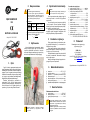
3 Użytkowanie
Aby wyindukować prąd w przewodniku, należy
otworzyć szczęki cęgów, objąć nimi przewodnik
i zgrubnie wyśrodkować przewodnik w stosunku
do szczęk. Następnie zamknąć cęgi i upewnić się,
że obie szczęki dokładnie do siebie przylegają.
Szczelina (utworzona z powierzchni czołowych
rdzenia) powinna być utrzymywana w ideal-
nej czystości.
4 Czyszczenie i konserwacja
UWAGA!
Należy stosować jedynie metody konserwacji po-
dane przez producenta w niniejszej instrukcji.
Przed czyszczeniem należy odłączyć cęgi od
mierzonego obwodu i miernika. Nie spryskiwać
cęgów wodą.
Kurz ze szczeliny usunąć za pomocą miękkiej
i suchej szmatki. Okresowo przetrzeć dostępną
żelazną część szczęk szmatką nasączoną olejem,
aby zapobiec ewentualnej korozji.
Cęgi można czyścić miękką, wilgotną szmatką
używając ogólnie dostępnych detergentów. Nie
należy używać żadnych rozpuszczalników.
5 Rozbiórka i utylizacja
Zużyty sprzęt elektryczny i elektroniczny nale-
ży gromadzić selektywnie, tj. nie umieszczać z
odpadami innego rodzaju.
Zużyty sprzęt elektryczny należy przekazać do
punktu zbiórki zgodnie z Ustawą o zużytym sprzę-
cie elektrycznym i elektronicznym.
Przed przekazaniem sprzętu do punktu zbiórki
nie należy samodzielnie demontować żadnych
części z tego sprzętu.
Należy przestrzegać lokalnych przepisów do-
tyczących wyrzucania opakowań.
6 Warunki odniesienia
a) temperatura .............................................+20°C …+26°C
b) wilgotność względna .......................................... 20…75%
c) przewodnik ........... wyśrodkowany w stosunku do szczęk
d) składowa stała prądu ................................................. brak
e) stałe pole magnetyczne .. <40 A/m (ziemskie pole magn.)
f) zmienne pole magnetyczne ....................................... brak
g) przewodniki w bezpośredniej bliskości ..... brak płynącego prądu
7 Dane techniczne
Podstawowe dane techniczne
a) prąd znamionowy ............................................ 1000 A AC
b) zakres częstotliwości ...................................30 Hz...5 kHz
c) sygnał wyjściowy dla max prądu ........................... 1 A AC
W przypadku stosowania cęgów z miernikiem
SONEL dokładność całkowita układu pomiaro-
wego miernik + cęgi podawana jest w instrukcji
obsługi danego miernika.
Dokładność cęgów podana w niniejszej instrukcji
nie jest sumą dokładności miernika i dokładno-
ści cęgów.
Pozostałe dane techniczne
a) rodzaj izolacji wg IEC 61010-1 .......................... podwójna
b) kategoria pomiarowa wg IEC 61010-1 ................ III 600 V
c) stopień ochrony obudowy wg IEC 60529
▪ szczęki zamknięte .................................................. IP40
▪ szczęki otwarte ....................................................... IP30
d) klasyfikacja palności wg UL 94 ................................... V0
e) wymiary ............................................. 216 × 111 × 45 mm
f) masa ................................................................... ok. 550 g
g) otwarcie szczęk ...................................................... 53 mm
h) wysokość otwartych szczęk .................................139 mm
i) maksymalna średnica przewodu mierzonego.... 52 mm
j) temperatura pracy ..................................... -10C…+55C
k) wilgotność względna ............................................... <90%
l) wysokość n.p.m. ................................................. ≤2000 m
m) wyrób spełnia wymagania EMC wg norm .........................
....................IEC 61000-6-3, IEC 61000-6-2, IEC IEC 61326-1
8 Producent
Prowadzącym serwis gwarancyjny
i pogwarancyjny jest:
SONEL S.A.
ul. Wokulskiego 11
58-100 Świdnica
tel. +48 74 884 10 53 (Biuro Obsługi Klienta)
e-mail: bok@sonel.pl
internet: www.sonel.pl
Wyprodukowano we Francji dla SONEL S.A.

TRANSMITTING CLAMP
N-1
USER MANUAL
Version 2.02 18.10.2023
1 Description
N-1 clamp is used to generate the test current in
the tested object. It is used in to locate cables and
measure earthing systems with the two-clamp meth-
od. Together with the current clamp, it eliminates the
need to use auxiliary probes driven into the ground,
and in case of locating cables, it enables identification
of cables without galvanic connection.
The maximum diameter of the tested conduc-
tor is 52 mm. The clamp is powered by a remova-
ble two-wire lead, terminated with 4 mm banana
plugs. The output signal is transmitted via two ba-
nana plugs.
2 Safety
NOTE!
Do not expose the clamp to water.
It is not allowed to use clamps on conductors
that conduct currents higher than 1200 A. Limit
the working time for currents over 1000 A ac-
cording to the following data.
Overloads
Current range
I ≤ 1000 A
1000 A I ≤ 1200 A
Operating
mode
continuous 1)
15 minutes of measure-
ment, followed by 30-
minute break
1) For frequencies f ≤ 1kHz. Limiting the maximum
current in continuous operation for frequencies above
1 kHz according to the following:
[kHz] f A1000
.
cont
I
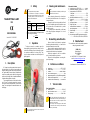
3 Operation
To induce a current in a conductor, open the
clamp slightly by turning the clasp, clamp it on the
conductor with flowing current and roughly center
the conductor relative to the clamp loop. Then
close the clamps and make sure that both jaws fit
tightly together.
The gap (formed by the faces of the core) should
be kept perfectly clean.
4 Cleaning and maintenance
NOTE!
Apply only maintenance methods specified by the
manufacturer in this manual.
Before cleaning, disconnect the clamp from
the tested circuit and the meter. Do not spray the
clamps with water.
Remove the dust from the gap with a soft and
dry cloth. Periodically wipe the accessible iron part
of the jaws with an oil-soaked cloth to prevent
possible corrosion.
The clamp may be cleaned with a soft, damp
cloth using all-purpose detergents. Do not use
any solvents.
5 Dismantling and utilisation
Worn-out electric and electronic equipment
should be gathered selectively, i.e. it must not be
placed with waste of another kind.
Worn-out electric equipment should be sent to
a collection point in accordance with the law of
waste electrical and electronic equipment.
Before the equipment is sent to a collection
point, do not dismantle any elements.
Observe the local regulations concerning dis-
posal of packages.
6 Reference conditions
a) temperature .............................................+20°C …+26°C
b) relative humidity ................................................. 20…75%
c) conductor ............................................ centred in the jaws
d) current constant component ..................................... none
e) permanent magnetic field .... <40 A/m (Earth's magnetic field)
f) variable, external magnetic field ............................... none
g) conductors in the immediate vicinity ........ no current flow
7 Technical data
Basic technical data
a) nominal current ................................................ 1000 A AC
b) output for maximum current .................................. 1 A AC
c) frequency range ...........................................30 Hz...5 kHz
When using the clamp with a SONEL meter, to-
tal measurement accuracy of the measuring sys-
tem of the meter and clamp is specified in the
manual of a given meter.
The accuracy of the clamp given in this manual
is not the sum of the accuracy of the meter and
accuracy of the clamp..
Other technical data
a) insulation type acc. to IEC 61010-1 ....................... double
b) measurement category acc. to IEC 61010-1 ...... III 600 V
c) ingress protection acc. to IEC 60529
▪ closed jaws ............................................................. IP40
▪ open jaws ................................................................ IP30
d) flammability classification acc. to UL 94 ..................... V0
e) dimensions ........................................ 216 × 111 × 45 mm
f) weight ................................................................. ca. 550 g
g) jaws opening distance ............................................ 53 mm
h) height of open jaws ..............................................139 mm
i) maximum diameter of tested cable .................... 52 mm
j) operating temperature ............................... -10C…+55C
k) relative humidity ...................................................... <90%
l) altitude a.s.l. ....................................................... ≤2000 m
m) the product meets the EMC requirements according to ...
................... IEC 61000-6-3, IEC 61000-6-2, IEC 61326-1
8 Manufacturer
The manufacturer, which also provides guarantee
and post-guarantee services:
SONEL S.A.
Wokulskiego 11
58-100 Świdnica
Poland
tel. +48 74 884 10 53 (Customer Service)
e-mail: customerserv[email protected]
web page: www.sonel.com
Manufactured in France for SONEL S.A.

PINZA DE TRANSMISIÓN
N-1
MANUAL DE USO
Versión 2.02 18.10.2023
1 Descripción
La pinza N-1 se utiliza para generar la
corriente de medición en el objeto bajo prueba. Se
utilizan en la localización de cables y mediciones
de puesta a tierra mediante el método de dos
pinzas. Junto con la pinza de medición, eliminan
la necesidad de utilizar sondas auxiliares clavadas
en el suelo, y en la localización permiten la
identificación de cables sin conexión galvánica.
El diámetro del conductor cubierto asciende a
52 mm como máximo. Las pinzas se alimentan
con un cable de 2 hilos reemplazable, terminado
con las clavijas tipo banana de 4 mm. La señal de
salida es introducida por dos enchufes
tipo banana.
2 Seguridad
¡ATENCIÓN!
No exponer la pinza al agua.
No está permitido usar la pinza en conductores
por los que pase corriente superior a 1200 A.
Debe limitar el tiempo de trabajo para corrientes
superiores a 1000 A según los siguientes datos.
Sobrecargas
Rango de
corrientes
I ≤ 1000 A
1000 A I ≤ 1200 A
Modo de
trabajo
continuo 1)
15 minutos de medición, a
continuación 30 minutos
de descanso
1) Para la frecuencia f ≤ 1 kHz. Limitación del valor
máximo de corriente para el trabajo continuo y la
frecuencia superior a 1 kHz de acuerdo con la
relación:
[kHz] f A1000
.
cont
I
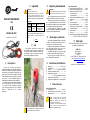
3 Uso
Para inducir la corriente en el conductor, abrir
las mordazas de la pinza, rodear un conductor con
la corriente y centrar el conductor en relación con
las mordazas. Luego cerrar la pinza y asegurarse
de que ambas mordazas encajen bien.
El hueco (formado de las superficies del núcleo)
debe mantenerse perfectamente limpio.
4 Limpieza y mantenimiento
¡ATENCIÓN!
Utilizar únicamente el método de conservación
proporcionado por el fabricante en este manual.
Antes de limpiar, desconectar la pinza del circuito
medido y del medidor. No rociar la pinza con agua.
Retirar el polvo del hueco con un paño suave y
seco. Limpiar periódicamente la parte de hierro
accesible de las mordazas con un paño empapado
en aceite para evitar una posible corrosión.
La pinza puede ser limpiada con un paño
suave y humedecido con detergentes comúnmente
utilizados. No usar ningún disolvente.
5 Desmontaje y utilización
Los residuos de aparatos eléctricos y electróni-
cos deben ser recogidos por separado, es decir, no
se depositan con los residuos de otro tipo.
El dispositivo electrónico debe ser llevado a un
punto de recogida conforme con la Ley de resi-
duos de aparatos eléctricos y electrónicos.
Antes de llevar el equipo a un punto de recogida
no se debe desarmar ninguna parte del equipo.
Hay que seguir las normativas locales en cu-
anto a la eliminación de envases.
6 Condiciones de referencia
a) temperatura .............................................+20°C …+26°C
b) humedad relativa ............................................... 20…75%
c) conductor ................................ centrado en las mordazas
d) componente constante de corriente ............................. sin
e) campo magnético constante ............................................
.......................... <40 A/m (campo magnético de la tierra)
f) campo magnético externo alterno ................................ sin
g) conductores en las inmediaciones ... sin corriente que fluya
7 Datos técnicos
Datos técnicos basicos
a) corriente nominal ............................................. 1000 A AC
b) señal de salida para la corriente máxima.............. 1 A AC
c) rango de frecuencia .....................................30 Hz...5 kHz
Cuando se utilizan pinzas con el medidor
SONEL, la precisión total del sistema de
medición se especifica en el manual de
instrucciones del medidor dado.
La precisión de la pinza indicada en este
manual no es la suma de la precisión del
medidor y la precisión de la pinza.
Otros datos técnicos
a) tipo de aislamiento según IEC 61010-1 ................... doble
b) categoría de medición según IEC 61010-1 ........ III 600 V
c) grado de protección según IEC 60529
▪ mordazas cerradas ................................................. IP40
▪ mordazas abiertas .................................................. IP30
d) clasificación de inflamabilidad según UL 94 ............... V0
e) dimensiones ...................................... 216 × 111 × 45 mm
f) peso .................................................................... ca. 550 g
g) apertura de mordazas ............................................ 53 mm
h) altura de mordazas abiertas ................................139 mm
i) diámetro máximo de conductor medido ............. 52 mm
j) temperatura de trabajo .............................. -10C…+55C
k) humedad relativa ..................................................... <90%
l) altura s.n.m. ........................................................ ≤2000 m
m) el producto cumple con los requisitos EMC según las normas
................... IEC 61000-6-3, IEC 61000-6-2, IEC 61326-1
8 Fabricante
El fabricante del dispositivo que presta el servicio
de garantía y postgarantía es:
SONEL S.A.
Wokulskiego 11
58-100 Świdnica
Polonia
tel. +48 74 884 10 53 (Servicio al cliente)
e-mail: customerserv[email protected]m
internet: www.sonel.com
Fabricado en Francia para SONEL S.A.

SENDZANGE
N-1
BEDIENUNGSANLEITUNG
Version 2.02 18.10.2023
1 Beschreibung
Die Stromzange N-1 dient zur Erzeugung des
Prüfstroms im Prüfobjekt. Sie wird bei Kabelor-
tungs- und Erdungsmessungen nach der Zwei-
zangenmethode eingesetzt. Zusammen mit einer
anderen Messzange macht sie den Einsatz von in
den Boden anzubringenden Hilfssonden überflüs-
sig und ermöglicht die Erkennung von Kabeln oh-
ne galvanische Verbindung bei der Ortung.
Max. Durchmesser des geprüften Leiters
52 mm. Die Zange wird über eine austauschbare
zweiadrige Leitung mit 4 mm Bananenstecker ein-
gespeist. Das Ausgangssignal wird über zwei Ba-
nanenstecker übertragen.
2 Sicherheit
ACHTUNG!
Die Messzange nicht Wasser aussetzen.
Die Messzange darf nicht an Leitern verwendet
werden, durch die Ströme über 1200 A fließen.
Bei Strömen über 1000 A die Arbeitszeit ent-
sprechend folgenden Angaben begrenzen.
Überlast
Strombereich
I ≤ 1000 A
1000 A I ≤ 1200 A
Modus
dauerhaft 1)
15 Minuten messen da-
nach, 30-Minuten Pause
1) Bei Frequenzen f ≤ 1 kHz. Limitieren Sie den Ma-
ximalstrom bei dauerhafter Messung bei Frequenzen
größer 1 kHz gemäß dem Verhältnis:
[kHz] f A1000
.
kont
I
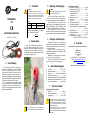
3 Verwendung
Backen der Sendzange öffnen, dabei den Lei-
ter mit den Backen umfassen und den Leiter in
Bezug auf die Backen ungefähr zentrieren, um
den Strom im Leiter zu induzieren. Dann die Zan-
ge schließen und darauf achten, dass beide Ba-
cken fest aneinander anliegen.
Der Spalt (gebildet durch die Stirnflächen des
Kerns) sollte vollkommen sauber gehalten werden.
4 Wartung und Reinigung
ACHTUNG!
Führen Sie nur Wartungsschritte durch wie in die-
ser Anleitung beschrieben durch.
Vor der Reinigung die Messzange vom zu
messenden Stromkreis und vom Messgerät tren-
nen. Die Messzange nicht mit Wasser besprühen.
Staub mit einem weichen, trockenen Tuch vom
Spalt entfernen. Den zugänglichen Eisenteil der
Backen regelmäßig mit einem ölgetränkten Tuch
abwischen, um mögliche Korrosion zu vermeiden.
Die Messzange kann mit einem weichen,
feuchten Tuch und mit üblichen Reinigungsmitteln
gereinigt werden. Keine Lösungsmittel verwenden.
5 Zerlegen und Entsorgen
Ausgediente Elektronik und elektronisches
Zubehör darf nicht zusammen mit gewöhnlichem
Hausmüll gesammelt werden, sondern muss ge-
trennt gehalten werden.
Bringen Sie diese zu den gesetzlich vorge-
schriebenen Sammelstellen für elektrisches und
elektronisches Zubehör.
Zerlegen Sie die Geräte nicht in Einzelteile,
bevor Sie es zum Entsorgen bringen.
Halten Sie die vorgeschriebenen Bestimmun-
gen zur Entsorgung von Verpackungen ein.
6 Referenzbedingungen
a) Temperatur ..............................................+20°C …+26°C
b) Relative Luftfeuchtigkeit .................................... 20…75%
c) Leiterposition .................... im Zentrum der Klemmbacken
d) Stromkonstantenkomponente .................................. keine
e) Permanentes magnetisches Feld ... <40 A/m (Erdmagnetfeld)
f) Variable des externen magnetischen Feldes ........... keine
g) Leiter in unmittelbarer Nähe .................... kein Stromfluss
7 Technische Daten
Grundlegende technische Daten
a) Nennstrom ....................................................... 1000 A AC
b) Maximale Ausgangsleistung .................................. 1 A AC
c) Frequenzbereich ..........................................30 Hz...5 kHz
Bei Verwendung von der Messzange mit dem
Messgerät von SONEL ist die Gesamtgenauig-
keit des Messsystems (Messgerät + Messzan-
ge) in der Bedienungsanleitung des jeweiligen
Messgeräts angegeben.
Die Genauigkeit der Zange, die in diesem Be-
dienungsanleitung angegeben ist, ist nicht die
Summe aus Messgerätgenauigkeit und Zangen-
genauigkeit.
Weitere technische Daten
a) Isolierklasse gem. IEC 61010-1 ............................ doppelt
b) Messkategorie gem. IEC 61010-1 ...................... III 600 V
c) Schutzklasse gem. IEC 60529
▪ geschlossene Backen ............................................. IP40
▪ offene Backen ......................................................... IP30
d) Brandklasse nach UL 94 ............................................. V0
e) Abmessungen ................................... 216 × 111 × 45 mm
f) Gewicht .............................................................. ca. 550 g
g) Öffnungsweite Zangenbacken ............................... 53 mm
h) Höhe offener Zangenbacken ...............................139 mm
i) Maximaler Durchmesser der zu testenden Leitungen .........
.................................................................................. 52 mm
j) Betriebstemperatur .................................... -10C…+55C
k) Relative Luftfeuchtigkeit .......................................... <90%
l) Höhe über n.N. ................................................... ≤2000 m
m) Elektromagnetische Verträglichkeit...................................
................... IEC 61000-6-3, IEC 61000-6-2, IEC 61326-1
8 Hersteller
Gerätehersteller für Garantieansprüche und Service:
SONEL S.A.
Wokulskiego 11
58-100 Świdnica
Polen
Tel. +48 74 884 10 53 (Kundenbetreuung)
E-Mail: customerservice@sonel.com
Webseite: www.sonel.com
Hergestellt in Frankreich für SONEL S.A.
-
 1
1
-
 2
2
-
 3
3
-
 4
4


Sonel MRU-200-GPS Benutzerhandbuch
- Typ
- Benutzerhandbuch
in anderen Sprachen
- English: Sonel MRU-200-GPS User manual
- español: Sonel MRU-200-GPS Manual de usuario
- polski: Sonel MRU-200-GPS Instrukcja obsługi
Verwandte Artikel
-
Sonel PQM-707 Benutzerhandbuch
-
Sonel MRU-200-GPS Benutzerhandbuch
-
Sonel PQM-707 Benutzerhandbuch
-
-
-
-
-
Sonel CMM-60 Benutzerhandbuch
-
Sonel CMM-40 Benutzerhandbuch
-