
Montageanleitung
Installation instructions
Notice de montage
AS-i CONTROLLERe
CONTRÔLEUReAS-i
AC1307/AC1317
Sachnr. 7390496/00 03/2005

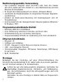
Bestimmungsgemäße Verwendung
• Der Controllereintegriert einen (AC1307) oder zwei AS-i Master
(AC1317), beide nach AS-i-Version 2.1, eine Kleinsteuerung und eine
Ethernet-IP-Schnittstelle
• Er steuert den Datenaustausch zur Sensor-/Aktuator-Ebene
• verarbeitet die Peripheriedaten im integrierten Prozessor (Signalvor-
verarbeitung)
• arbeitet als stand-alone-Steuerung mit Datenaustausch zum PC
(Visualisierung)
• kommuniziert mit der übergeordneten Steuerungsebene (Ethernet /
IP, Modbus /TCP)
Programmierschnittstelle RS232C
• Baudrate 4800 bis 115200Baud
• max. Entfernung zwischen Controllereund Host: 20m
• Potentialtrennung zur Controllere-Versorgung
• Programmierkabel E70320 zur Verbindung zum Host erforderlich
Ethernet-Schnittstelle
• Ethernet / IP
• 10Mbps und 100Mbps
• TCP/IP - Transport Control Protocol/ Internet Protocol
• UDP - User Datagram Protocol
• IT-Funktionalität: Filesystem, FTP-Server, Telnet-Server, HTTP-Server,
E-mail Client
• RJ45, Twisted-Pair
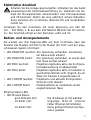
Montage
Befestigen Sie den Controllereauf einer 35mm-Profilschiene. Die
Schutzart des Geräts beträgt IP 20, daher sollte es an einem geschütz-
ten Ort montiert werden (z.B. Schaltschrank).
Achten Sie auf eine betauungsfreie Umgebung. Vermeiden Sie
übermäßige Staubentwicklung, Vibrations- und Stoßbelastun-
gen. Die Luftzirkulation durch die Lüftungsöffnungen darf nicht
behindert werden.
Vermeiden Sie eine Montage in direkter Nähe zu Frequenzum-
richtern.
2

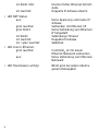
Elektrischer Anschluß
Schalten Sie die Anlage spannungsfrei. Schließen Sie das Gerät
entsprechend der Klemmenbeschriftung an. Verbinden Sie nie-
mals die Minuspotentiale untereinander oder Minuspotentiale
und FE-Anschluß. Stellen Sie eine elektrisch sichere Erdverbin-
dung zwischen AS-i Controllere(Klemme FE) und Gerät-Erdan-
schluß her.
Versorgen Sie den Controlleremit einer Spannung von 24V DC
(20 ... 30V PELV), z. B. aus dem 24V Netzteil DN2011 der ifm electro-
nic. Der Anschluß erfolgt an den Klemmen +24V und 0V.
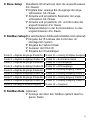
Bedien- und Anzeigeelemente
Sie werden von drei Diagnose-LEDs auf dem Controllereüber den
Zustand des Masters (AC1307) /der Master (AC1317) und der ange-
schlossenen System informiert.
• LED PWR/COM leuchtet: AS-i Spannung vorhanden, mindestens
ein Slave wurde erkannt
• LED PWR/COM blinkt: AS-i Spannung vorhanden, es wurde aber
kein Slave korrekt erkannt
• LED PROJ leuchtet: Projektierungsmodus aktiv, die Konfigura-
tionsüberwachung ist abgeschaltet
• LED PROJ blinkt: Projektierungsmodus aktiv, Umschalten in
geschützten Betrieb nicht möglich, da ein
Slave mit Adresse 0 angeschlossen ist
• LED CONF/PF leuchtet: Projektierte und aktuelle Konfiguration
stimmen nicht überein
• LED CONF/PF blinkt: Peripheriefehler an mindestens einem
angeschlossenen Slave
Ethernet Status LEDs
• LED Module Status:
grün blinkend 1Hz: Die IP-Adresse ist frei wählbar
rot blinkt 1Hz: Ungültige MAC-ID (interner
Fehler Ethernet-Schnittstelle)
rot blinkt 2Hz: Keine gültige Ethernet-Konfigu-
ration geladen
3

rot blinkt 4Hz: Interner Fehler Ethernet-Schnitt-
stelle
rot leuchtet: Doppelte IP-Adresse erkannt
• LED NET Status:
aus: Keine Spannung oder keine IP-
Adresse
grün leuchtet: Verbunden mit Ethernet /IP
grün blinkt: Keine Verbindung zum Ethernet /
IP hergestellt
rot blinkt: Verbindungs-Timeout
rot leuchtet: Doppelte IP-Adresse
rot / grün leuchtet: Selbsttest
• LED Link to Ethernet:
grün leuchtet: Controllereist mit einem
Ethernet-Netzwerk verbunden
aus: Keine Verbindung zum Ethernet-
Netzwerk
• LED Transmission activity: Blinkt grün bei jedem übertra-
genem Datenpaket
4

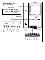
5
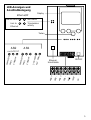
ASI2 ASI1
RS232C
ASI2 +
ASI2 -
ASI1 +
ASI1 -
FE
+24V
0V
PWR/COM
PROJ
CONF/PF
PWR/COM
PROJ
CONF/PF
24V PWR
PLC RUN
Module Status Net Status
Link to
Ethernet Transmission
activity
Ethernet/IP
LED-Anzeigen und
Anschlußbelegung
Ethernet-
Schnittstelle
Display
Tasten
nur AC1317

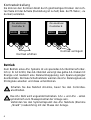
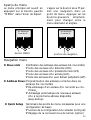
Kontrasteinstellung
Sie können den Kontrast direkt durch gleichzeitiges Drücken der rech-
ten Taste mit der ∆-Taste (Darstellung ist zu hell) bzw. der ∇-Taste (...zu
dunkel) verstellen.
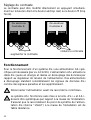
Betrieb
Zum Betrieb eines AS-i Systems ist ein spezielles AS-i Netzteil erforder-
lich (z. B. AC1216). Das AS-i Netzteil versorgt das gelbe AS-i Kabel mit
Energie und realisiert eine Datenentkoppelung zum Spannungsregler
des Netzteils. Normale Schaltnetzteile würden die AS-i Datensignale als
Störsignale ansehen und diese unterdrücken.
Schalten Sie das Netzteil stromlos, bevor Sie den Controllere
anschließen.
Das AS-i Netz wird ungeerdet betrieben. AS-i + und AS-i - sollen
symmetrisch zum Massepotential der Anlage sein.
Verbinden Sie den Symmetriepunkt des AS-i Netzteils (Klemme
„Shield“) niederohmig mit der Masse der Anlage.
6
∆
∆
ifm electronic
Controller E
MENU USER
∆
∆
ifm electronic
Controller E
MENU USER
Kontrast erhöhen Kontrast verringern

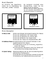
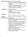
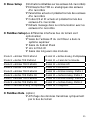
Menü-Übersicht
Menü-Navigation
O Slave Lists (Prüfen der Adressen der angeschlossenen AS-i Slaves)
∇Liste der detektierten AS-i Slaves (LDS)
∇Liste der projektierten AS-i Slaves (LPS)
∇Liste der aktivierten AS-i Slaves (LAS)
∇Liste der AS-i Slaves mit Peripheriefehler (LPF)
O Address Slave (Programmierung der korrekten Adressen in den
angeschlossenen AS-i Slaves)
∇Umadressieren eines am Controllereangeschlos-
senen AS-i Slaves
∇Automatisches adressieren neuer AS-i Slaves auf
die nächste freie Adresse (Easy Startup)
O Quick Setup (Zusammenfassung der für eine Grundkonfiguration
erforderlichen Menüpunkte)
∇Die aktuelle AS-i Konfiguration einlesen (Config all)
∇Einstellung der Feldbusverbindung (optional)
7
∆
∆
ifm electronic
Controller E
MENU USER
∆
∆
ifm electronic
Controller E
MENU USER
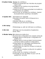
MENU-Taste Navigations-Tasten
Sie erreichen das Hauptmenü,
indem Sie im Startdisplay die
linke Taste „MENU“ drücken.
Sie navigieren innerhalb eines
Menüpunktes, indem Sie die
Tasten ∆oder ∇drücken.
Drücken Sie die Tasten gleichzei-
tig, um zwischen deutschem und
englischem Menü zu wechseln.

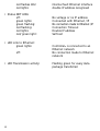
O System Setup (Einstellung des ControllereGerätes)
∇Baudrate der seriellen Programmierschnittstelle
∇IP Adresse der Ethernet Programmierschnittstelle
(optional)
∇Eingabe des Passwortes zur Freigabe von Ände-
rungen in der Systemkonfiguration
∇Update der Firmware des Controllere(spezielle
Programmiersoftware erforderlich)
O System Info (Geräte Informationen)
∇Hardware und Firmware Versionsnummern dieses
Controllere
∇Seriennummer dieses Controllere
∇Aktuelle/Maximale SPS Zykluszeit
O PLC Setup ∇Starten oder Stoppen der SPS im Controllere
O PLC Info (Anzeige Anwenderprogramm-Name, Autor, Datum)
O Master Setup (AS-i Masterflags)
∇Die aktuelle AS-i Konfiguration einlesen (Config all)
∇Wechsel in den Projektierungsmodus: Konfigura-
tion des AS-i Systems
∇Wechsel in den geschützten Betrieb: Normalbe-
trieb (der Master überwacht die Konfiguration)
∇Deaktivieren der automatischen AS-i Slaves
Adressierung im geschützten Betrieb
∇Deaktivieren des AS-i Resets beim Verlassen des
Projektierungsmodus
∇Anzeige des Config-Errors Zählers des ange-
schlossenen AS-i Systems
∇Reset des Config-Errors Zählers
∇Anzeige der prozentualen Fehlerrate des ange-
schlossenen AS-i Systems
8

O Slave Setup (Detaillierte Informationen über die angeschlossenen
AS-i Slaves)
∇Digitale bzw. analoge Ein-/Ausgänge der ange-
schlossenen AS-i Slaves
∇Aktuelle und projektierte Parameter der ange-
schlossenen AS-i Slaves
∇Aktuelle und projektierte I/O- und ID-Codes der
angeschlossenen AS-i Slaves
∇Telegrammfehler in der Kommunikation zu den
angeschlossenen AS-i Slaves
O Fieldbus Setup(Die verschiedenen Feldbusschnittstellen sind optional)
∇Eingabe der IP-Adresse des Controllereim
überlagerten System
∇Eingabe der Subnet Mask
∇Auslesen der MAC-ID
∇Eingabe der Modullängen
O Fieldbus Data (optional)
∇Anzeige der über den Feldbus zyklisch übertra-
genen Daten
9
Modul 1 =Digitale Eingänge Master1A
Modul 2 =Digitale Ausgänge Master1A
Modul 3 =Digitale Eingänge Master2A
Modul 4 =Digitale Ausgänge Master2A
Modul 5 =Digitale Eingänge Master1B
Modul 6 =Digitale Ausgänge Master1B
Modul 7 =Digitale Eingänge Master2B
Modul 8 =Digitale Ausgänge Master2B
Modul 9 =Analog Multiplex Eingang
Modul 10 = Analog Multiplex Ausgang
Modul 11 = Kommando Kanal
Modul 12 = SPS Eingänge
Modul 13 = SPS Ausgänge
Modul 14 = Analog Eingang Master 1
Modul 15 = Analog Ausgang Master 1
Modul 16 = Analog Eingang Master 2
Modul 17 = Analog Ausgang Master 2
Modul 18 = Diagnose

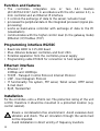
Function and features
•The controllereintegrates one or two AS-i masters
(AC1307/AC1317, both in accordance with the AS-i version 2.1), a
mini controller and an Ethernet IP interface.
•It controls the exchange of data to the sensor/actuator level
•processes the peripheral data in the integrated processor (signal pre-
processing)
•works as stand-alone controller with exchange of data to the PC
(visualisation)
•communicates with the higher control level (in the gateway mode)
(Ethernet / IP, Modbus /TCP)
Programming interface RS232C
•Baud rate 4800 to 115,200 baud
•Max. distance between controllereand host: 20m
•Potential separation from the controllerepower supply
•Programming cable E70320 for connection to host required
Ethernet interface
•Ethernet / IP
10Mbps and 100Mbps
•TCP/IP - Transport Control Protocol/ Internet Protocol
•UDP - User Datagram Protocol
•IT functionality: file system, FTP server, Telnet server, HTTP server,
E-mail client
•RJ45, Twisted-Pair
Installation
Fix the controllereonto a 35mm rail. The protection rating of the unit
is IP20, therefore it should be mounted in a protected location (e.g.
control cabinet).
Ensure a condensation-free environment. Avoid excessive dust,
vibration and shock. The air circulation through the vents must
not be impeded.
Avoid installation in direct vicinity of frequency inverters.
10

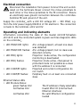
Electrical connection
Disconnect the installation from power. Connect the unit as indi-
cated on the terminals. Never connect the minus potentials to
each other or the minus potentials to the FE connection. Ensure
an electrically save ground connection between AS-i controllere
(terminal FE) and ground of the unit.
Supply the controllerewith a 24V DC voltage (20 ... 30V PELV), e.g.
from the 24V power supply DN2011 of ifm electronic. The connection
is made to the terminals +24V and 0V.
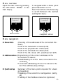
Operating and indicating elements
Information concerning the state of the master (AC1307)/masters
/AC1317) and the connected system is given via three diagnostic LEDs
on the controllere.
•LED PWR/COM lights: AS-i voltage present, at least one slave
was detected
•LED PWR/COM flashes: AS-i voltage present, but no slave was
detected correctly
•LED PROJ lights: Projection mode active, the configuration
monitoring is deactivated
•LED PROJ flashes: Projection mode active, changeover to
protected mode not possible as a slave
with the address 0 is connected
•LED CONF/PF lights: Projected and current configuration do
not match
•LED CONF/PF flashes: Periphery fault on at least one connected
slave
Ethernet Status LEDs
•LED Module Status:
green flashes 1Hz: The IP address is freely selectable
red flashes 1Hz: Invalid MAC ID (internal fault
Ethernet interface)
red flashes 2Hz: No valid Ethernet configuration
loaded
11

red flashes 4Hz: internal fault Ethernet interface
red lights: double IP address recognised
•Status NET LEDs:
off: No voltage or no IP address
green lights: Connected with Ethernet / IP
green flashing: No connection made to Ethernet / IP
red flashing: Connection Timeout
red lights: Double IP address
red/ green light: Self-test
•LED Link to Ethernet:
green lights: Controllereis connected to an
Ethernet network
off: No connection made to Ethernet
network
•LED Transmission activity: Flashing green for every data
package transferred
12

13
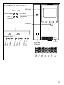
ASI2 ASI1
RS232C
ASI2 +
ASI2 -
ASI1 +
ASI1 -
FE
+24V
0V
PWR/COM
PROJ
CONF/PF
PWR/COM
PROJ
CONF/PF
24V PWR
PLC RUN
Module Status Net Status
Link to
Ethernet Transmission
activity
Ethernet/IP
LED indicators and
pin connection
Ethernet
interface
display
pushbuttons
only AC1317

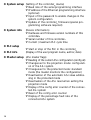
Contrast setting
The contrast can be directly changed by simultaneously pressing the
right button and the ∆-button (too bright) or the ∇−button (too dark).
Operation
To operate an AS-i system a special AS-i power supply is required (e.g.
AC1216). The AS-i power supply supplies the yellow AS-i cable with
energy and implements a data decoupling to the voltage regulator of
the power supply. Standard switched-mode power supplies would
consider the AS-i data signals as interference signals and suppress
them.
Disconnect the power supply before connecting the controllere.
The AS-i system is operated ungrounded. AS-i + and AS-i - are to
be symmetrical to the ground potential of the installation. Ensure
a low resistance connection of the symmetry point of the AS-i
power supply (terminal shield) to the ground of the installation.
14
∆
∆
ifm electronic
Controller E
MENU USER
∆
∆
ifm electronic
Controller E
MENU USER
increase contrast decrease contrast

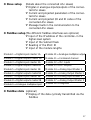
Menu overview
Menu navigation
O Slave lists (Checking of the addresses of the connected AS-i
slaves)
∇List of the detected AS-i slaves (LDS)
∇List of the projected AS-i slaves (LPS)
∇List of the activated AS-i slaves (LAS)
∇List of the AS-i slaves with periphery fault (LPF)
O Address slave (Programming of the correct addresses in the
connected AS-i slaves)
∇Readdressing of an AS-i slave connected to the
controllere
∇Automatic addressing of new AS-i slaves to the
next free address (easy startup)
O Quick setup (Summary of the menu points required for a basic
configuration)
∇Reading of the current AS-i configuration (config
all)
∇Setting of the fieldbus connection (optional) 15
∆
∆
ifm electronic
Controller E
MENU USER
∆
∆
ifm electronic
Controller E
MENU USER
Menu button navigation buttons
Open the main menu by pressing
the left button "MENU" in the
start display.
To navigate within a menu point
press the button ∆or ∇.
Press the buttons simultaneously
to switch between the German
and English menu.

O System setup (Setting of the controlleredevice)
∇Baud rate of the serial programming interface
∇IP address of the Ethernet programming interface
(optional)
∇Input of the password to enable changes in the
system configuration
∇Update of the controllerefirmware (special pro-
gramming software required)
O System info (Device information)
∇Hardware and firmware version numbers of this
controllere
∇Serial number of this controllere
∇Current /maximum PLC cycle time
O PLC setup ∇Start or stop of the PLC in the controllere
O PLC info (Display of the user program name, author, date)
O Master setup (AS-i master flags)
∇Reading of the current AS-i configuration (config all)
∇Changeover to the projection mode: configurati-
on of the AS-i system
∇Changeover to the protected mode: standard
mode (the master monitors the configuration)
∇Deactivation of the automatic AS-i slave addres-
sing in the protected mode
∇Deactivation of the AS-i reset when exiting the
projection mode
∇Display of the config error counter of the connec-
ted AS-i system
∇Reset of the config error counter
∇Display of the percentage fault rate of the
connected AS-i system
16

O Slave setup (Details about the connected AS-i slaves)
∇Digital or analogue inputs/outputs of the connec-
ted AS-i slaves
∇Current and projected parameters of the connec-
ted AS-i slaves
∇Current and projected I/O and ID codes of the
connected AS-i slaves
∇Message faults in the communication to the
connected AS-i slaves
O Fieldbus setup(The different fieldbus interfaces are optional)
∇Input of the IP address of the controllerein the
higher-level system
∇Input of the Subnet Mask
∇Reading of the MAC ID
∇Input of the module lengths
O Fieldbus data (optional)
∇Display of the data cyclically transmitted via the
fieldbus
17
Module 1 = Digital inputs master 1A
Module 2 = Digital outputs master 1A
Module 3 = Digital inputs master 2A
Module 4 = Digital outputs master2A
Module 5 = Digital inputs master 1B
Module 6 = Digital outputs master1B
Module 7 = Digital inputs master 2B
Module 8 = Digital outputs master2B
Module 9 = Analogue multiplex input
Module 10 = Analogue multiplex output
Module 11 = Command channel
Module 12 = PLC inputs
Module 13 = PLC outputs
Module 14 = Analog Input Master 1
Module 15 = Analog Output Master 1
Module 16 = Analog Input Master 2
Module 17 = Analog Output Master 2
Module 18 = Diagnosis

Fonctionnement et caractéristiques
•Le contrôleureintègre un ou deux maîtres AS-i (AC1307/AC1317, les
deux selon la version AS-i 2.1), une unité de prétraitement et une
interface Ethernet.
•Il contrôle l'échange de données avec le niveau capteurs/ action-
neurs,
•traite les données périphériques dans le processeur intégré (prétrai-
tement des signaux),
•travaille comme contrôleur autonome avec échange de données
avec le PC (visualisation),
•peut communiquer avec le niveau système de commande supérieur
(Ethernet / IP, Modbus /TCP)
Interface de programmation RS232C
•Débit de transmission 4800 à 115.200 baud
•Distance maximum entre le contrôleureet l'hôte: 20m
•Séparation galvanique avec l'alimentation du contrôleure
•Câble de programmation E70320 nécessaire pour raccorder l'hôte
Interface Ethernet
•Ethernet / IP
•10Mbps et 100Mbps
•TCP/ IP - Transport Control Protocol/ Internet Protocol
•UDP - User Datagram Protocol
•fonctionnalité IT: file system, FTP server, Telnet server, HTTP server,
E-mail client
•RJ45, Twisted-Pair
Montage
Fixer le contrôleresur un rail profilé 35mm. La protection de l'appareil
est IP20, de ce fait il doit être monté dans un lieu protégé (par ex.
armoire électrique).
S'assurer d'un environnement sans condensation. Eviter les excès
de poussières, les vibrations et les chocs. La circulation d'air à tra-
vers les trous d'évent ne doit pas être gênée.
Eviter un montage à proximité directe des variateurs de fréquence.
18

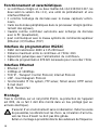
Raccordement électrique
Mettre l'installation hors tension. Raccorder l'appareil selon les
indications sur les bornes. Ne jamais raccorder les potentiels néga-
tifs l'un à l'autre ou les potentiels négatifs à la connexion FE. S'as-
surer d'une connexion électrique sûre entre le contrôleureAS-i
(borne FE) et la terre de l'appareil.
Alimenter le contrôleureen 24V DC (20 ... 30V TBTP), par ex. via l'ali-
mentation 24V DN2011 d'ifm electronic. Le raccordement se fait aux
bornes +24V et 0V.
Eléments de service et d'indication
L'état du maître (AC1307) /des maîtres (AC1317) et du système rac-
cordé est indiqué par trois LED de diagnostic sur le contrôleure.
•LED PWR/COM allumée: Alimentation AS-i présente, au moins un
esclave a été détecté
•LED PWR/COM clignote: Alimentation AS-i présente, mais aucun
esclave n'a été détecté correctement
•LED PROJ allumée: Mode projet actif, la surveillance de la
configuration est désactivée
•LED PROJ clignote: Mode projet actif, passage dans le mode
protégé impossible car un esclave avec
l'adresse 0 est raccordé
•LED CONF/PF allumée: La configuration présélectionnée et la
configuration actuelle ne sont pas identiques
•LED CONF/PF clignote: Défaut périphérie sur au moins un esclave
raccordé
LED d'état Ethernet
•LED Module Status:
verte clignote 1Hz: L'adresse IP peut être sélec
tionnée librement
rouge clignote 1Hz: MAC ID non valable (défaut
interne interface Ethernet)
rouge clignote 2Hz: Aucune configuration Ethernet
valable chargée
19

rouge clignote 4Hz: défaut interne interface Ethernet
rouge allumée: adresse IP double reconnue
•LED d'état NET:
éteinte: Aucune tension ou aucune
adresse IP
verte allumée : Raccordé à l'Ethernet / IP
verte clignote : Aucun raccordement à
l'Ethernet / IP réalisé
rouge clignote : Timeout raccordement
rouge allumée: Adresse IP double
rouge / verte allumées: Auto-test
•LED Link to Ethernet:
verte allumée : Controllereest raccordé à un
système Ethernet
éteinte: Aucun raccordement au système
Ethernet
•LED Transmission activity: Clignote en vert pour chaque
paquet de données transmis
20
Seite wird geladen ...
Seite wird geladen ...
Seite wird geladen ...
Seite wird geladen ...
Seite wird geladen ...
-
 1
1
-
 2
2
-
 3
3
-
 4
4
-
 5
5
-
 6
6
-
 7
7
-
 8
8
-
 9
9
-
 10
10
-
 11
11
-
 12
12
-
 13
13
-
 14
14
-
 15
15
-
 16
16
-
 17
17
-
 18
18
-
 19
19
-
 20
20
-
 21
21
-
 22
22
-
 23
23
-
 24
24
-
 25
25


in anderen Sprachen
- English: IFM AC1307 Installation guide
- français: IFM AC1307 Guide d'installation
Verwandte Artikel
Andere Dokumente
-
Pepperl+Fuchs VBG-PN-K20-D-EV24 Bedienungsanleitung
-
-
-
-
Pepperl+Fuchs VBG-EC-K30-DMD-S32-EV Bedienungsanleitung
-
-