
Distribution box | Installation basics
Luchtverdeelkast | Installatieprincipes
Caisson de distribution | Règles
d’installation de base
Luftverteiler | Installationsgrundlagen
Box distribuzione | Istruzioni di base
AIR EXCELLENT 800 SERIES
The Netherlands
Ubbink bv
Verhuellweg 9
NL - 6980 AADoesburg
Tel.+31 (0) 313 480 300
Fax+31 (0) 313 473 859
UK
Ubbink UK Ltd
Unit 2 Redbourne Park
Liliput Road
Brackmills Industrial Estate
Northampton
NN4 7DT
Tel.+44 (0) 1604 433 000
Fax+44 (0) 1604 433 001
France
Ubbink France S.A.S.
13, rue de Bretagne – Z.A. Malabry – BP4301
F - 44243La Chapelle Sur Erdre Cedex
Tel.+33 (0) 251 134 646
Fax+33 (0) 251 134 546
Belgium
Ubbink nv
Jan Samijnstraat 9
B - 9050Gentbrugge
Tel.+32 (0) 923 711 00
Fax+32 (0) 923 711 29
© 2017 - Ubbink Centrotherm Group | Content is subject
to change without notice | Availability and configurations
may differ per country | Subject to misprint | All rights
reserved and we explicitly exclude any liability arising of
or in connection with this document
100000072434/1701
2
ENGLISH (EN)
INTRODUCTION
The Air Excellent air distribution system is specially designed for central mechanical ventilation systems with heat
recovery and central mechanical extract units. It is a modular system composed of a manifold, semi-rigid duct and
various accessories. The semi-rigid duct is available in various circular and semi-circular dimensions.
Flow restrictors are used to distribute the right amount of air to and from the rooms. The correct setting, i.e. the
number of rings to be removed from the flow restrictors, can be determined by using our configuration tool. Please
contact your Ubbink distributor for more information about the configuration tool.
The required ventilation rates vary from country to country and are determined by national regulations.
“All work must be undertaken according to all local and national health and
safety regulations”.
GENERAL INSTALLATION PROCESS
1. Design the installation.
2. Use the Ubbink configuration tool to calculate the ventilation capacities and system pressure loss and
determine the optimal location for the distribution boxes to minimize system pressure loss
3. Cut the semi-rigid ducts to the required length and lay them out according to the design. Allow 100 - 150 mm
extra length to ensure ease of assembly. Use vertical and horizontal bends if required.
4. Mark the semi-rigid ducts to indicate whether the ducts are used for either air supply or air extract.
5. Cut the valve adaptors to the required height and install them.
6. Use the mounting clips to fix the semi-rigid duct where necessary.
7. Use the red seal ring for each connection.
8. Use the configuration tool to determine how many rings to cut out of each flow restrictor and install the flow
restrictors between the semi-rigid duct and distribution box.
9. Measure the air flows after installation.
DUTCH (NL)
INLEIDING
Air Excellent is speciaal ontworpen voor gebalanceerde ventilatiesystemen met warmteterugwinning. Het is een
modulair systeem dat bestaat uit een flexibele buis, diverse accessoires en een luchtverdeelkast. De flexibele buis is
verkrijgbaar in verschillende ronde en half-ronde afmetingen.
Voor een goed werkend systeem is het belangrijk dat elke ruimte de juiste luchthoeveelheid krijgt. Dit wordt bereikt
door het gebruik van restrictieringen. De juiste instelling hiervan (het aantal ringen dat wordt verwijderd) kan worden
bepaald met behulp van een drukverliesberekening. Ubbink biedt een configuratietool om dit te doen. Neem contact op
met uw Ubbink distributeur voor advies en ondersteuning.
De benodigde capaciteit varieert per land en is gekoppeld aan de nationale
regelgeving.
“Al het werk moet worden uitgevoerd op basis van alle lokale en nationale
gezondheids-en veiligheids voorschriften.”
ALGEMEEN INSTALLATIEPROCES
1. Maak een systeemontwerp
2. Bepaal met behulp van de Ubbink configuratie tool de benodigde capaciteiten, maak een
drukverliesberekening en kies de optimale plaats voor de luchtverdeelkasten.
3. Bepaal de benodigde lengte van de flexibele buizen en kort ze in. Neem 100 mm tot 150 mm extra lengte voor
een eenvoudige montage. Gebruik verticale en horizontale bochten indien nodig.
4. Markeer alle flexibele buizen of ze voor de luchttoevoer of de luchtafvoer zijn.
5. Kort de ventieladapters en de vloer roosters in tot de benodigde maat.
6. Monteer de bevestigingbeugels waar nodig
7. Gebruik de juiste koppeling/afdichting voor elke verbinding.
8. Bepaal met de configuratie tool de juiste instelling voor de restrictieringen. Monteer ze vervolgens tussen de
luchtverdeelkast en de flexibele buis.
9. Controleer alle capaciteiten na installatie.
11
2
3
1
3
FRENCH (FR)
INTRODUCTION
Le système de distribution Air Excellent est spécialement conçu pour des systèmes de ventilation double flux, simple
flux, ballon thermodynamique sur air extrait. C’est un système composé d’un conduit flexible, d’accessoires et de
caissons de répartition. Les conduits semi-rigides existent dans différentes sections circulaires et semi-circulaires.
L’utilisation de joints spéciaux en fait un système hautement étanche, classe B selon la norme EN 12237.
Afin d’assurer le bon fonctionnement du système, il est important d’obtenir pour chaque pièce le bon débit d’air grâce à
l’utilisation des réducteurs de débit. Le réglage correct (exemple : le nombre d’anneaux à retirer des réducteurs de débit)
des réducteurs doit être déterminé par le calcul de la perte de pression qui est effectué avant l’installation. Ubbink
fournit pour cela un logiciel de calcul. Le bureau d’étude Ubbink se tient à votre disposition pour réaliser un calcul
détaillé.
Attention, les débits exigés varient selon chaque pays et chaque réglementation
nationale.
Tout chantier doit être entrepris selon les réglementations locales et nationales
de sécurité et de santé.
PROCÉDÉ GÉNÉRAL D’INSTALLATION
1. Faire un plan de l’installation
2. Utiliser l’outil de configuration Ubbink afin de calculer les débits et les pertes de pression du système et
déterminer les endroits optimaux ou installer les caissons de distribution de manière à réduire ainsi les pertes
de pression du système.
3. Couper les conduits semi-rigides à la longueur requise et les placer selon le plan de l’installation. Prendre
100-150 mm de longueur supplémentaire pour plus de sécurité en cas d’assemblage. Utiliser les coudes
horizontaux et verticaux si nécessaire.
4. Marquer les conduits semi-rigides afin d’indiquer si ces conduits sont utilisés pour l’air insufflé ou l’air extrait.
5. Couper les tés de raccordement à la hauteur requise et les installer
6. Utiliser les colliers de fixation afin de fixer le conduit semi-rigide ou cela est nécessaire
7. Utiliser le joint rouge pour chaque connexion
8. Utiliser l’outil de configuration Ubbink afin de déterminer combien d’anneaux doit- on enlever de chaque
réducteur de débit et installer les réducteurs de débit entre les conduits semi-rigides et les caissons de
distribution.
9. Mesurer les débits d’air après installation
10
3
1
4
2
2
3
1
4
5
2
2
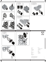
EN Connecting AE45SC duct
NL Aansluiten van AE45SC slang
FR Connection de conduit AE45SC
DE Anschluss AE45SC
IT Connessione del condotto AE45SC
4
GERMAN (DE)
EINLEITUNG
Das Luftverteilsystem Air Excellent wurde speziell für Lüftungssysteme mit Wärmerückgewinnung entwickelt. Die
Entwicklung beinhaltet in erster Linie Wellrohre, Zubehörteile und entsprechende Luftverteiler. Das Luftverteilsystem
ist in unterschiedlichen Nennweiten erhältlich. Spezielle Dichtelemente garantieren eine hohe Luftdichtheit des
Systems.
Um ein Lüftungssystem ausgeglichen betreiben zu können, ist es wichtig, dass die genaue Luftmenge für jeden Raum
eingehalten wird. Dies wird hier mittels spezieller Drosseln realisiert. Diese werden entsprechend der nach Berechnung
vorgegebenen Werte eingestellt (z.B. Vorgabe der zu entfernenden Ringe der Drossel). Ubbink stellt ein Hilfsmittel für
diese Konfiguration zur Verfügung. Bei Fragen dazu oder benötigter Berechnung kontaktieren Sie bitte Ihren Ubbink-
Händler.
Je nach Land ist die benötigte Luftmenge unterschiedlich anzusetzen, diese wird
in den nationalen Vorgaben (Normen, Vorschriften) landesspezifisch geregelt.
Bitte nehmen Sie die entsprechend vorgegebenen Werte an.
Montieren Sie grundsätzlich immer unter Berücksichtigung der Regeln für
Sicherheit und Gesundheit. Auch anderweitige, nicht separat aufgeführte
nationale Richtlinien müssen berücksichtigt werden.
ALLGEMEINE BESCHREIBUNG
1. Erstellen Sie eine Prinzip-Skizze der geplanten Installation.
2. Führen Sie eine Berechnung der geplanten Anlage durch (z.B. mit dem Ubbink-Konfigurator) und bestimmen
Sie die optimale Position für die Luftverteiler.
3. Messen und Kürzen Sie die Wellrohre auf die erforderliche Länge. Um die Installation zu vereinfachen
empfehlen wir, die Längen um ca. 10 cm bis 15 cm zu erhöhen. Falls erforderlich, verwenden Sie horizontale
oder vertikale Bögen.
4. Markieren Sie die Wellrohre je nach Gebrauch (Zuluft oder Abluft).
5. Bereiten Sie die Decken- und/oder Bodenauslässe vor und installieren Sie diese.
6. Montieren Sie die Befestigungsschellen, wo erforderlich.
7. Verbinden Sie die Wellrohre mit allen Anschlüssen mit dem dafür vorgesehenen Dichtring.
8. Installieren Sie die Drosseln, die Sie vorher passend zur Berechnung eingestellt haben, an der Verbindung zum
Luftverteiler.
9. Prüfen Sie nach der Montage die Luftmengen.
9
2
3
1
EN Connecting AE35SC / AE55SC duct
NL Aansluiten van AE35SC / AE55SC slang
FR Connection de conduit AE35SC / AE55SC
DE Anschluss AE35SC / AE55SC
IT Connessione del condotto AE35SC / AE55SC
5
ITALIAN (IT)
INTRODUZIONE
Il sistema di distribuzione aria Air Excellent è stato specificatamente progettato per la ventilazione meccanica
controllata degli ambienti con recupero di calore. Si tratta di un sistema modulare composto da condotto flessibile, vari
accessori ed un box di distribuzione. I condotti flessibili semi-ovali e circolari sono disponibili in varie dimensioni. L’uso
degli anelli di tenuta speciali rende il sistema estremamente ermetico.
Per un buon funzionamento del sistema di ventilazione è importante assicurare ad ogni stanza la giusta portata di
aria, ciò si ottiene mediante l’utilizzo di diaframmi / regolatori di portata a corredo dei Box distribuzione. La corretta
impostazione (es.: il numero di anelli da rimuovere ai regolatori di portata) dei regolatori deve essere determinata
calcolando le cadute di pressione prima dell’installazione. Ubbink fornisce uno strumento allo scopo “Configuratore AE”.
Si prega di contattare il proprio distributore Ubbink per un calcolo dettagliato!
Le portate richieste variano per ogni nazione essendo legate alle normative
nazionali. Si prega di fare riferimento alla normativa vigente per i valori corretti.
Rispettare le normative di sicurezza e salute. Controllare le regolamentazioni
nazionali pertinenti.
FASI DI INSTALLAZIONE
1. Realizzare un disegno schematico dell’installazione
2. Calcolare le portate e le perdite di pressione con l’uso del configuratore Ubbink.
3. Scegliere il posizionamento ottimale dei box di distribuzione
4. Individuare il miglior posizionamento per l’installazione degli adattatori per valvole o griglie.
5. Misurare e tagliare a misura i condotti flessibili. Tenere una lunghezza da 10 cm a 15 cm in più per assicurare
una connessione agevole. Usare le curve verticali e orizzontali se necessarie
6. Tagliare gli adattatori per valvole e per griglie e installarli
7. Montare i collari di fissaggio ove necessari
8. Contrassegnare tutti i condotti flessibili se per estrazione o immissione.
9. Collegare i tubi flessibili a tutti i connettori, usando una guarnizione rossa per ogni connessione
10. Installare tutti i diaframmi/regolatori di portata necessari tra il box di distribuzione e la guarnizione rossa
predisposta sul tubo flessibile. Il configuratore indica l’apertura del diaframma da predisporre
11. Controllare tutte le portate dopo l’installazione.
8
123 123
1
2
3
1
2
3
4
4
EN Connecting AE34C duct
NL Aansluiten van AE34C slang
FR Connection de conduit AE34C
DE Anschluss AE34C
IT Connessione del condotto AE34C
EN Connecting AE23C / AE48C duct
NL Aansluiten van AE23C / AE48C slang
FR Connection de conduit AE23C / AE48C
DE Anschluss AE23C / AE48C
IT Connessione del condotto AE23C / AE48C
6
8 16
24
540
510
4x 5 mm
4x
4x 6 mm
Ø 6 mm
7
1
2
Ø 125
Ø 160
1
2

Distribution box | Installation basics
Luchtverdeelkast | Installatieprincipes
Caisson de distribution | Règles
d’installation de base
Luftverteiler | Installationsgrundlagen
Box distribuzione | Istruzioni di base
AIR EXCELLENT 800 SERIES
The Netherlands
Ubbink bv
Verhuellweg 9
NL - 6980 AADoesburg
Tel.+31 (0) 313 480 300
Fax+31 (0) 313 473 859
UK
Ubbink UK Ltd
Unit 2 Redbourne Park
Liliput Road
Brackmills Industrial Estate
Northampton
NN4 7DT
Tel.+44 (0) 1604 433 000
Fax+44 (0) 1604 433 001
France
Ubbink France S.A.S.
13, rue de Bretagne – Z.A. Malabry – BP4301
F - 44243La Chapelle Sur Erdre Cedex
Tel.+33 (0) 251 134 646
Fax+33 (0) 251 134 546
Belgium
Ubbink nv
Jan Samijnstraat 9
B - 9050Gentbrugge
Tel.+32 (0) 923 711 00
Fax+32 (0) 923 711 29
© 2017 - Ubbink Centrotherm Group | Content is subject
to change without notice | Availability and configurations
may differ per country | Subject to misprint | All rights
reserved and we explicitly exclude any liability arising of
or in connection with this document
100000072434/1701
2
ENGLISH (EN)
INTRODUCTION
The Air Excellent air distribution system is specially designed for central mechanical ventilation systems with heat
recovery and central mechanical extract units. It is a modular system composed of a manifold, semi-rigid duct and
various accessories. The semi-rigid duct is available in various circular and semi-circular dimensions.
Flow restrictors are used to distribute the right amount of air to and from the rooms. The correct setting, i.e. the
number of rings to be removed from the flow restrictors, can be determined by using our configuration tool. Please
contact your Ubbink distributor for more information about the configuration tool.
The required ventilation rates vary from country to country and are determined by national regulations.
“All work must be undertaken according to all local and national health and
safety regulations”.
GENERAL INSTALLATION PROCESS
1. Design the installation.
2. Use the Ubbink configuration tool to calculate the ventilation capacities and system pressure loss and
determine the optimal location for the distribution boxes to minimize system pressure loss
3. Cut the semi-rigid ducts to the required length and lay them out according to the design. Allow 100 - 150 mm
extra length to ensure ease of assembly. Use vertical and horizontal bends if required.
4. Mark the semi-rigid ducts to indicate whether the ducts are used for either air supply or air extract.
5. Cut the valve adaptors to the required height and install them.
6. Use the mounting clips to fix the semi-rigid duct where necessary.
7. Use the red seal ring for each connection.
8. Use the configuration tool to determine how many rings to cut out of each flow restrictor and install the flow
restrictors between the semi-rigid duct and distribution box.
9. Measure the air flows after installation.
DUTCH (NL)
INLEIDING
Air Excellent is speciaal ontworpen voor gebalanceerde ventilatiesystemen met warmteterugwinning. Het is een
modulair systeem dat bestaat uit een flexibele buis, diverse accessoires en een luchtverdeelkast. De flexibele buis is
verkrijgbaar in verschillende ronde en half-ronde afmetingen.
Voor een goed werkend systeem is het belangrijk dat elke ruimte de juiste luchthoeveelheid krijgt. Dit wordt bereikt
door het gebruik van restrictieringen. De juiste instelling hiervan (het aantal ringen dat wordt verwijderd) kan worden
bepaald met behulp van een drukverliesberekening. Ubbink biedt een configuratietool om dit te doen. Neem contact op
met uw Ubbink distributeur voor advies en ondersteuning.
De benodigde capaciteit varieert per land en is gekoppeld aan de nationale
regelgeving.
“Al het werk moet worden uitgevoerd op basis van alle lokale en nationale
gezondheids-en veiligheids voorschriften.”
ALGEMEEN INSTALLATIEPROCES
1. Maak een systeemontwerp
2. Bepaal met behulp van de Ubbink configuratie tool de benodigde capaciteiten, maak een
drukverliesberekening en kies de optimale plaats voor de luchtverdeelkasten.
3. Bepaal de benodigde lengte van de flexibele buizen en kort ze in. Neem 100 mm tot 150 mm extra lengte voor
een eenvoudige montage. Gebruik verticale en horizontale bochten indien nodig.
4. Markeer alle flexibele buizen of ze voor de luchttoevoer of de luchtafvoer zijn.
5. Kort de ventieladapters en de vloer roosters in tot de benodigde maat.
6. Monteer de bevestigingbeugels waar nodig
7. Gebruik de juiste koppeling/afdichting voor elke verbinding.
8. Bepaal met de configuratie tool de juiste instelling voor de restrictieringen. Monteer ze vervolgens tussen de
luchtverdeelkast en de flexibele buis.
9. Controleer alle capaciteiten na installatie.
11
2
3
1
3
FRENCH (FR)
INTRODUCTION
Le système de distribution Air Excellent est spécialement conçu pour des systèmes de ventilation double flux, simple
flux, ballon thermodynamique sur air extrait. C’est un système composé d’un conduit flexible, d’accessoires et de
caissons de répartition. Les conduits semi-rigides existent dans différentes sections circulaires et semi-circulaires.
L’utilisation de joints spéciaux en fait un système hautement étanche, classe B selon la norme EN 12237.
Afin d’assurer le bon fonctionnement du système, il est important d’obtenir pour chaque pièce le bon débit d’air grâce à
l’utilisation des réducteurs de débit. Le réglage correct (exemple : le nombre d’anneaux à retirer des réducteurs de débit)
des réducteurs doit être déterminé par le calcul de la perte de pression qui est effectué avant l’installation. Ubbink
fournit pour cela un logiciel de calcul. Le bureau d’étude Ubbink se tient à votre disposition pour réaliser un calcul
détaillé.
Attention, les débits exigés varient selon chaque pays et chaque réglementation
nationale.
Tout chantier doit être entrepris selon les réglementations locales et nationales
de sécurité et de santé.
PROCÉDÉ GÉNÉRAL D’INSTALLATION
1. Faire un plan de l’installation
2. Utiliser l’outil de configuration Ubbink afin de calculer les débits et les pertes de pression du système et
déterminer les endroits optimaux ou installer les caissons de distribution de manière à réduire ainsi les pertes
de pression du système.
3. Couper les conduits semi-rigides à la longueur requise et les placer selon le plan de l’installation. Prendre
100-150 mm de longueur supplémentaire pour plus de sécurité en cas d’assemblage. Utiliser les coudes
horizontaux et verticaux si nécessaire.
4. Marquer les conduits semi-rigides afin d’indiquer si ces conduits sont utilisés pour l’air insufflé ou l’air extrait.
5. Couper les tés de raccordement à la hauteur requise et les installer
6. Utiliser les colliers de fixation afin de fixer le conduit semi-rigide ou cela est nécessaire
7. Utiliser le joint rouge pour chaque connexion
8. Utiliser l’outil de configuration Ubbink afin de déterminer combien d’anneaux doit- on enlever de chaque
réducteur de débit et installer les réducteurs de débit entre les conduits semi-rigides et les caissons de
distribution.
9. Mesurer les débits d’air après installation
10
3
1
4
2
2
3
1
4
5
2
2
EN Connecting AE45SC duct
NL Aansluiten van AE45SC slang
FR Connection de conduit AE45SC
DE Anschluss AE45SC
IT Connessione del condotto AE45SC
4
GERMAN (DE)
EINLEITUNG
Das Luftverteilsystem Air Excellent wurde speziell für Lüftungssysteme mit Wärmerückgewinnung entwickelt. Die
Entwicklung beinhaltet in erster Linie Wellrohre, Zubehörteile und entsprechende Luftverteiler. Das Luftverteilsystem
ist in unterschiedlichen Nennweiten erhältlich. Spezielle Dichtelemente garantieren eine hohe Luftdichtheit des
Systems.
Um ein Lüftungssystem ausgeglichen betreiben zu können, ist es wichtig, dass die genaue Luftmenge für jeden Raum
eingehalten wird. Dies wird hier mittels spezieller Drosseln realisiert. Diese werden entsprechend der nach Berechnung
vorgegebenen Werte eingestellt (z.B. Vorgabe der zu entfernenden Ringe der Drossel). Ubbink stellt ein Hilfsmittel für
diese Konfiguration zur Verfügung. Bei Fragen dazu oder benötigter Berechnung kontaktieren Sie bitte Ihren Ubbink-
Händler.
Je nach Land ist die benötigte Luftmenge unterschiedlich anzusetzen, diese wird
in den nationalen Vorgaben (Normen, Vorschriften) landesspezifisch geregelt.
Bitte nehmen Sie die entsprechend vorgegebenen Werte an.
Montieren Sie grundsätzlich immer unter Berücksichtigung der Regeln für
Sicherheit und Gesundheit. Auch anderweitige, nicht separat aufgeführte
nationale Richtlinien müssen berücksichtigt werden.
ALLGEMEINE BESCHREIBUNG
1. Erstellen Sie eine Prinzip-Skizze der geplanten Installation.
2. Führen Sie eine Berechnung der geplanten Anlage durch (z.B. mit dem Ubbink-Konfigurator) und bestimmen
Sie die optimale Position für die Luftverteiler.
3. Messen und Kürzen Sie die Wellrohre auf die erforderliche Länge. Um die Installation zu vereinfachen
empfehlen wir, die Längen um ca. 10 cm bis 15 cm zu erhöhen. Falls erforderlich, verwenden Sie horizontale
oder vertikale Bögen.
4. Markieren Sie die Wellrohre je nach Gebrauch (Zuluft oder Abluft).
5. Bereiten Sie die Decken- und/oder Bodenauslässe vor und installieren Sie diese.
6. Montieren Sie die Befestigungsschellen, wo erforderlich.
7. Verbinden Sie die Wellrohre mit allen Anschlüssen mit dem dafür vorgesehenen Dichtring.
8. Installieren Sie die Drosseln, die Sie vorher passend zur Berechnung eingestellt haben, an der Verbindung zum
Luftverteiler.
9. Prüfen Sie nach der Montage die Luftmengen.
9
2
3
1
EN Connecting AE35SC / AE55SC duct
NL Aansluiten van AE35SC / AE55SC slang
FR Connection de conduit AE35SC / AE55SC
DE Anschluss AE35SC / AE55SC
IT Connessione del condotto AE35SC / AE55SC
5
ITALIAN (IT)
INTRODUZIONE
Il sistema di distribuzione aria Air Excellent è stato specificatamente progettato per la ventilazione meccanica
controllata degli ambienti con recupero di calore. Si tratta di un sistema modulare composto da condotto flessibile, vari
accessori ed un box di distribuzione. I condotti flessibili semi-ovali e circolari sono disponibili in varie dimensioni. L’uso
degli anelli di tenuta speciali rende il sistema estremamente ermetico.
Per un buon funzionamento del sistema di ventilazione è importante assicurare ad ogni stanza la giusta portata di
aria, ciò si ottiene mediante l’utilizzo di diaframmi / regolatori di portata a corredo dei Box distribuzione. La corretta
impostazione (es.: il numero di anelli da rimuovere ai regolatori di portata) dei regolatori deve essere determinata
calcolando le cadute di pressione prima dell’installazione. Ubbink fornisce uno strumento allo scopo “Configuratore AE”.
Si prega di contattare il proprio distributore Ubbink per un calcolo dettagliato!
Le portate richieste variano per ogni nazione essendo legate alle normative
nazionali. Si prega di fare riferimento alla normativa vigente per i valori corretti.
Rispettare le normative di sicurezza e salute. Controllare le regolamentazioni
nazionali pertinenti.
FASI DI INSTALLAZIONE
1. Realizzare un disegno schematico dell’installazione
2. Calcolare le portate e le perdite di pressione con l’uso del configuratore Ubbink.
3. Scegliere il posizionamento ottimale dei box di distribuzione
4. Individuare il miglior posizionamento per l’installazione degli adattatori per valvole o griglie.
5. Misurare e tagliare a misura i condotti flessibili. Tenere una lunghezza da 10 cm a 15 cm in più per assicurare
una connessione agevole. Usare le curve verticali e orizzontali se necessarie
6. Tagliare gli adattatori per valvole e per griglie e installarli
7. Montare i collari di fissaggio ove necessari
8. Contrassegnare tutti i condotti flessibili se per estrazione o immissione.
9. Collegare i tubi flessibili a tutti i connettori, usando una guarnizione rossa per ogni connessione
10. Installare tutti i diaframmi/regolatori di portata necessari tra il box di distribuzione e la guarnizione rossa
predisposta sul tubo flessibile. Il configuratore indica l’apertura del diaframma da predisporre
11. Controllare tutte le portate dopo l’installazione.
8
123 123
1
2
3
1
2
3
4
4
EN Connecting AE34C duct
NL Aansluiten van AE34C slang
FR Connection de conduit AE34C
DE Anschluss AE34C
IT Connessione del condotto AE34C
EN Connecting AE23C / AE48C duct
NL Aansluiten van AE23C / AE48C slang
FR Connection de conduit AE23C / AE48C
DE Anschluss AE23C / AE48C
IT Connessione del condotto AE23C / AE48C
6
8 16
24
540
510
4x 5 mm
4x
4x 6 mm
Ø 6 mm
7
1
2
Ø 125
Ø 160
1
2
-
 1
1
-
 2
2


in anderen Sprachen
- français: Ubbink 0188581 Guide d'installation
- italiano: Ubbink 0188581 Guida d'installazione
Verwandte Papiere
Sonstige Unterlagen
-
Groupe Brandt SD1644F2 Bedienungsanleitung
-
Groupe Brandt SD1618F2 Bedienungsanleitung
-
Whirlpool TP 95 G NL Benutzerhandbuch
-
Whirlpool BP 215 GS Benutzerhandbuch
-
-
GE GUD24GSSJWW Installationsanleitung
-
Indesit PP 73 G AT Benutzerhandbuch
-
Truma Trumatic E 4000 Bedienungsanleitung