Grundfos AP51,65.36V Installation And Operating Instructions Manual
- Typ
- Installation And Operating Instructions Manual

GRUNDFOS INSTRUCTIONS
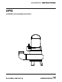
AP51
Installation and operating instructions

2

Table of contents
3
AP51
Declaration of conformity . . . . . . . . . . . . . . . . . . . . . . . . . . . . . . . . . . . . . . . . . . 4
English (GB)
Installation and operating instructions. . . . . . . . . . . . . . . . . . . . . . . . . . . . . . . . . 6
Dansk (DK)
Monterings- og driftsinstruktion. . . . . . . . . . . . . . . . . . . . . . . . . . . . . . . . . . . . . 11
Deutsch (DE)
Montage- und Betriebsanleitung . . . . . . . . . . . . . . . . . . . . . . . . . . . . . . . . . . . . 16
Ελληνικά (GR)
Οδηγίες εγκατάστασης και λειτουργίας . . . . . . . . . . . . . . . . . . . . . . . . . . . . . . . 22
Español (ES)
Instrucciones de instalación y funcionamiento . . . . . . . . . . . . . . . . . . . . . . . . . 27
Français (FR)
Notice d'installation et de fonctionnement. . . . . . . . . . . . . . . . . . . . . . . . . . . . . 32
Italiano (IT)
Istruzioni di installazione e funzionamento . . . . . . . . . . . . . . . . . . . . . . . . . . . . 37
Nederlands (NL)
Installatie- en bedieningsinstructies . . . . . . . . . . . . . . . . . . . . . . . . . . . . . . . . . 42
Português (PT)
Instruções de instalação e funcionamento . . . . . . . . . . . . . . . . . . . . . . . . . . . . 47
Suomi (FI)
Asennus- ja käyttöohjeet. . . . . . . . . . . . . . . . . . . . . . . . . . . . . . . . . . . . . . . . . . 52
Svenska (SE)
Monterings- och driftsinstruktion . . . . . . . . . . . . . . . . . . . . . . . . . . . . . . . . . . . . 57
Appendix 1 . . . . . . . . . . . . . . . . . . . . . . . . . . . . . . . . . . . . . . . . . . . . . . . 62

Declaration of conformity
4
Declaration of conformity
GB: EC declaration of conformity
We, Grundfos, declare under our sole responsibility that the products
AP51, to which this declaration relates, are in conformity with these
Council directives on the approximation of the laws of the EC member
states:
– Machinery Directive (2006/42/EC).
Standard useds: EN 809: 1998, EN 60204-1 and
ISO 12100-1 and -2.
– Low Voltage Directive (2006/95/EC).
Standards used: EN 60034-5, EN 60335-1 and EN 60335-2-41.
– EMC Directive (2004/108/EC).
Standards used: EN 61000-3-2, EN 61000-3-3, EN 61000-6-1,
EN 61000-6-2, EN 61000-6-3, EN 61000-6-4, EN 55014-1 and
EN 55014-2.
– Construction Products Directive (89/106/EEC).
Standard used: EN 12050-1-4.
DK: EF-overensstemmelseserklæring
Vi, Grundfos, erklærer under ansvar at produkterne AP51 som denne
erklæring omhandler, er i overensstemmelse med disse af Rådets
direktiver om indbyrdes tilnærmelse til EF-medlemsstaternes
lovgivning:
– Maskindirektivet (2006/42/EF).
Anvendte standarder: EN 809: 1998, EN 60204-1 og
ISO 12100-1 og -2.
– Lavspændingsdirektivet (2006/95/EF).
Anvendte standarder: EN 60034-5, EN 60335-1 og
EN 60335-2-41.
– EMC-direktivet (2004/108/EF).
Anvendte standarder: EN 61000-3-2, EN 61000-3-3,
EN 61000-6-1, EN 61000-6-2, EN 61000-6-3, EN 61000-6-4,
EN 55014-1 og EN 55014-2.
– Byggevaredirektivet (89/106/EØF).
Anvendt standard: EN 12050-1-4.
DE: EG-Konformitätserklärung
Wir, Grundfos, erklären in alleiniger Verantwortung, dass die
Produkte AP51, auf die sich diese Erklärung bezieht, mit den
folgenden Richtlinien des Rates zur Angleichung der
Rechtsvorschriften der EU-Mitgliedsstaaten übereinstimmen:
– Maschinenrichtlinie (2006/42/EG).
Normen, die verwendet wurden: EN 809: 1998, EN 60204-1 und
ISO 12100-1 und -2.
– Niederspannungsrichtlinie (2006/95/EG).
Normen, die verwendet wurden: EN 60034-5, EN 60335-1 und
EN 60335-2-41.
– EMV-Richtlinie (2004/108/EG).
Normen, die verwendet wurden: EN 61000-3-2, EN 61000-3-3,
EN 61000-6-1, EN 61000-6-2, EN 61000-6-3, EN 61000-6-4,
EN 55014-1 und EN 55014-2.
– Bauprodukterichtlinie (89/106/EWG).
Norm, die verwendet wurde: EN 12050-1-4.
GR: ∆ήλωση συμμόρφωσης EC
Εμείς, η Grundfos, δηλώνουμε με αποκλειστικά δική μας ευθύνη ότι
τα προϊόντα AP51 στα οποία αναφέρεται η παρούσα δήλωση,
συμμορφώνονται με τις εξής Οδηγίες του Συμβουλίου περί
προσέγγισης των νομοθεσιών των κρατών μελών της ΕΕ:
– Οδηγία για μηχανήματα (2006/42/EC).
Πρότυπα που χρησιμοποιήθηκαν: EN 809: 1998, EN 60204-1 και
ISO 12100-1 και -2.
– Οδηγία χαμηλής τάσης (2006/95/EC).
Πρότυπα που χρησιμοποιήθηκαν: EN 60034-5, EN 60335-1 και
EN 60335-2-41.
– Οδηγία
Ηλεκτρομαγνητικής Συμβατότητας (EMC) (2004/108/EC).
Πρότυπα που χρησιμοποιήθηκαν: EN 61000-3-2, EN 61000-3-3,
EN 61000-6-1, EN 61000-6-2, EN 61000-6-3, EN 61000-6-4,
EN 55014-1 και EN 55014-2.
– Οδηγία Παραγωγής Προϊόντων (89/106/EEC).
Πρότυπο που χρησιμοποιήθηκε: EN 12050-1-4.
ES: Declaración CE de conformidad
Nosotros, Grundfos, declaramos bajo nuestra entera responsabilidad
que los productos AP51, a los cuales se refiere esta declaración,
están conformes con las Directivas del Consejo en la aproximación
de las leyes de las Estados Miembros del EM:
– Directiva de Maquinaria (2006/42/CE).
Normas aplicadas: EN 809: 1998, EN 60204-1 y ISO 12100-1 y -2.
– Directiva de Baja Tensión (2006/95/CE).
Normas aplicadas: EN 60034-5, EN 60335-1 y EN 60335-2-41.
– Directiva EMC (2004/108/CE).
Normas aplicadas: EN 61000-3-2, EN 61000-3-3, EN 61000-6-1,
EN 61000-6-2, EN 61000-6-3, EN 61000-6-4, EN 55014-1 y
EN 55014-2.
– Directiva de Productos de Construcción (89/106/CEE).
Norma aplicada: EN 12050-1-4.
FR: Déclaration de conformité CE
Nous, Grundfos, déclarons sous notre seule responsabilité, que
les produits AP51, auxquels se réfère cette déclaration, sont
conformes aux Directives du Conseil concernant le rapprochement
des législations des Etats membres CE relatives aux normes
énoncées ci-dessous :
– Directive Machines (2006/42/CE).
Normes utilisées : EN 809 : 1998, EN 60204-1 et
ISO 12100-1 et -2.
– Directive Basse Tension (2006/95/CE).
Normes utilisées : EN 60034-5, EN 60335-1 et EN 60335-2-41.
– Directive Compatibilité Electromagnétique CEM (2004/108/CE).
Normes utilisées : EN 61000-3-2, EN 61000-3-3, EN 61000-6-1,
EN 61000-6-2, EN 61000-6-3, EN 61000-6-4, EN 55014-1 et
EN 55014-2.
– Directive sur les Produits de Construction (89/106/CEE).
Norme utilisée : EN 12050-1-4.
IT: Dichiarazione di conformità CE
Grundfos dichiara sotto la sua esclusiva responsabilità che i prodotti
AP51, ai quali si riferisce questa dichiarazione, sono conformi alle
seguenti direttive del Consiglio riguardanti il riavvicinamento delle
legislazioni degli Stati membri CE:
– Direttiva Macchine (2006/42/CE).
Norme applicate: EN 809: 1998, EN 60204-1 e ISO 12100-1 e -2.
– Direttiva Bassa Tensione (2006/95/CE).
Norme applicate: EN 60034-5, EN 60335-1 e EN 60335-2-41.
– Direttiva EMC (2004/108/CE).
Norme applicate: EN 61000-3-2, EN 61000-3-3, EN 61000-6-1,
EN 61000-6-2, EN 61000-6-3, EN 61000-6-4, EN 55014-1 e
EN 55014-2.
– Direttiva Prodotti da Costruzione (89/106/CEE).
Norma applicata: EN 12050-1-4.
NL: EC overeenkomstigheidsverklaring
Wij, Grundfos, verklaren geheel onder eigen verantwoordelijkheid dat
de producten AP51 waarop deze verklaring betrekking heeft,
in overeenstemming zijn met de Richtlijnen van de Raad in zake de
onderlinge aanpassing van de wetgeving van de EG Lidstaten
betreffende:
– Machine Richtlijn (2006/42/EC).
Gebruikte normen: EN 809: 1998, EN 60204-1 en
ISO 12100-1 en -2.
– Laagspannings Richtlijn (2006/95/EC).
Gebruikte normen: EN 60034-5, EN 60335-1 en EN 60335-2-41.
– EMC Richtlijn (2004/108/EC).
Gebruikte normen: EN 61000-3-2, EN 61000-3-3, EN 61000-6-1,
EN 61000-6-2, EN 61000-6-3, EN 61000-6-4, EN 55014-1 en
EN 55014-2.
– Bouwproducten Richtlijn (89/106/EEC).
Gebruikte norm: EN 12050-1-4.

Declaration of conformity
5
PT: Declaração de conformidade CE
A Grundfos declara sob sua única responsabilidade que os produtos
AP51, aos quais diz respeito esta declaração, estão em
conformidade com as seguintes Directivas do Conselho sobre
a aproximação das legislações dos Estados Membros da CE:
– Directiva Máquinas (2006/42/CE).
Normas utilizadas: EN 809: 1998, EN 60204-1 e
ISO 12100-1 e -2.
– Directiva Baixa Tensão (2006/95/CE).
Normas utilizadas: EN 60034-5, EN 60335-1 e EN 60335-2-41.
– Directiva EMC (compatibilidade electromagnética)
(2004/108/CE).
Normas utilizadas: EN 61000-3-2, EN 61000-3-3, EN 61000-6-1,
EN 61000-6-2, EN 61000-6-3, EN 61000-6-4, EN 55014-1 e
EN 55014-2.
– Directiva Produtos Construção (89/106/CEE).
Norma utilizada: EN 12050-1-4.
FI: EY-vaatimustenmukaisuusvakuutus
Me, Grundfos, vakuutamme omalla vastuullamme, että tuotteet AP51,
joita tämä vakuutus koskee, ovat EY:n jäsenvaltioiden lainsäädännön
yhdenmukaistamiseen tähtäävien Euroopan neuvoston direktiivien
vaatimusten mukaisia seuraavasti:
– Konedirektiivi (2006/42/EY).
Sovellettavat standardit: EN 809: 1998, EN 60204-1 ja
ISO 12100-1 ja -2.
– Pienjännitedirektiivi (2006/95/EY).
Sovellettavat standardit: EN 60034-5, EN 60335-1 ja
EN 60335-2-41.
– EMC-direktiivi (2004/108/EY).
Sovellettavat standardit: EN 61000-3-2, EN 61000-3-3,
EN 61000-6-1, EN 61000-6-2, EN 61000-6-3, EN 61000-6-4,
EN 55014-1 ja EN 55014-2.
– Rakennustuotedirektiivi (89/106/ETY).
Sovellettu standardi: EN 12050-1-4.
SE: EG-försäkran om överensstämmelse
Vi, Grundfos, försäkrar under ansvar att produkterna AP51, som
omfattas av denna försäkran, är i överensstämmelse med rådets
direktiv om inbördes närmande till EU-medlemsstaternas lagstiftning,
avseende:
– Maskindirektivet (2006/42/EG).
Tillämpade standarder: EN 809: 1998, EN 60204-1 och
ISO 12100-1 och -2.
– Lågspänningsdirektivet (2006/95/EG).
Tillämpade standarder: EN 60034-5, EN 60335-1 och
EN 60335-2-41.
– EMC-direktivet (2004/108/EG).
Tillämpade standarder: EN 61000-3-2, EN 61000-3-3,
EN 61000-6-1, EN 61000-6-2, EN 61000-6-3, EN 61000-6-4,
EN 55014-1 och EN 55014-2.
– Byggproduktdirektivet (89/106/EEG).
Tillämpad standard: EN 12050-1-4.
Bjerringbro, 1st September 2011
Svend Aage Kaae
Technical Director
Grundfos Holding A/S
Poul Due Jensens Vej 7
8850 Bjerringbro, Denmark
Person authorised to compile technical file and
empowered to sign the EC declaration of conformity.

English (GB)
6
English (GB) Installation and operating instructions
Original installation and operating instructions.
CONTENTS
Page
1. General description
1.1 Applications
Grundfos AP51 pumps are designed for pumping:
• wastewater,
• sludge-containing water, and
• groundwater.
If permitted by local laws and regulations, the
Grundfos AP51 pumps may be used for the pumping
of sewage from single and multifamily houses.
The compact design makes the pumps suitable for
both temporary and permanent installation.
Furthermore, the pumps are suitable for
free-standing installation as well as installation by
means of an auto-coupling guide rail system.
1.1.1 Explosive environments
Use the explosion-proof AP pump versions for
applications involving the risk of explosion.
Note: In each individual case the explosion
classification of the pump must be approved by the
local authorities for use at the desired installation
site.
1.2 Operating conditions
1.2.1 pH-value
AP pumps in permanent installations can cope with
pH-values ranging from 4 to 10.
1.2.2 Liquid temperature
Liquid temperature: 0 °C to +40 °C.
For short periods up to +60 °C.
1.2.3 Density of pumped liquid
Maximum density of pumped liquid: 1100 kg/m
3
.
1.2.4 Installation depth
Maximum 10 metres below liquid level.
1.2.5 Level of pumped liquid
The lowest stop level must always be above the top
of the pump housing.
1.2.6 Operation
Maximum 15 starts per hour.
Note: The pumps are designed for intermittent
operation only.
1.3 Sound pressure level
The sound pressure level of the pump is lower than
the limiting values stated in the EC Council Directive
2006/42/EC relating to machinery.
2. Safety
3. Transportation and storage
The pump may be transported and stored in a
vertical or horizontal position. Make sure that it
cannot roll or fall over.
Always lift the pump by its carrying handle, never by
the motor cable or the hose/pipe.
For long periods of storage, the pump must be
protected against moisture and heat.
After a long period of storage, the pump should be
inspected before it is put into operation. Make sure
that the impeller can rotate freely. Pay special
attention to the shaft seals and the cable entry.
4. Installation
The loose nameplate supplied with the pump should
be fixed at the installation site.
Prior to installation, check the oil level in the oil
chamber, see section 7. Maintenance and service.
1. General description
6
1.1 Applications
6
1.2 Operating conditions
6
1.3 Sound pressure level
6
2. Safety
6
3. Transportation and storage
6
4. Installation
6
4.1 Installation on auto-coupling
7
4.2 Free-standing installation
7
4.3 Pumps supplied with control box
7
4.4 Separate level controllers
7
5. Electrical connection
7
5.1 Motor protection
8
6. Start-up
8
6.1 Direction of rotation
8
7. Maintenance and service
8
7.1 Contaminated pumps
9
8. Fault finding chart
10
9. Disposal
10
Prior to installation, read these
installation and operating
instructions. Installation and
operation must comply with local
regulations and accepted codes of
good practice.
Pump installation in wells must be
carried out by specially trained
persons.

English (GB)
7
4.1 Installation on auto-coupling
See figs. A and B, pages 62 and 63.
Pumps for permanent installation can be installed on
a stationary auto-coupling and operated completely
or partially submerged in the pumped liquid.
1. Drill mounting holes for guide rail bracket on the
inside of the pit and fasten the guide rail bracket
provisionally with two screws.
2. Place the auto-coupling base unit on the bottom
of the pit. Use a plumb line to establish the
correct positioning. Fasten with heavy-duty
expansion bolts. If the bottom of the pit is
uneven, the auto-coupling base unit must be
supported so that it is level when being fastened.
3. Assemble the discharge line in accordance with
the generally accepted procedures and without
exposing the line to distortion or tension.
4. Insert the guide rails in the rings of the
auto-coupling base unit and adjust the length of
the rails accurately to the guide rail bracket.
5. Unscrew the provisionally fastened guide rail
bracket, fit it on top of the guide rails and finally
fasten it firmly to the pit wall.
Note: The guide rails must not have any axial play
as this would cause noise during pump operation.
6. Clean out debris from the pit before lowering the
pump into the pit.
7. Fit the auto-coupling half on to the discharge port
of the pump. Then slide the guide bar of this
coupling half between the guide rails and lower
the pump into the pit by means of a chain. When
the pump reaches the auto-coupling base unit,
the pump will automatically connect tightly.
8. Hang up the end of the chain on a suitable hook
at the top of the pit.
9. Adjust the length of the motor cable by coiling it
up on a relief fitting, so the cable is not damaged
during operation. Fasten the relief fitting to a
suitable bracket at the top of the pit. Make sure
that the cables are not sharply bent or pinched.
Note: The end of the cable must not be submerged,
as water may penetrate through the cable into the
motor.
4.2 Free-standing installation
See fig. C, page 64.
The AP51 pumps have pump housing and base
stand cast in one unit for free-standing installation.
For free-standing installation of the pumps, fit a 90 °
elbow to the discharge port. The pump can be
installed with a hose or rigid pipe and valves.
In order to facilitate service of the pump, fit a flexible
union or coupling to the discharge line for easy
separation.
If a hose is used, make sure that the hose does not
buckle and that the inside diameter of the hose
matches that of the discharge port.
If a rigid pipe is used, the union or coupling,
non-return valve and isolating valve should be fitted
in the sequence mentioned, as seen from the pump
side.
Lower the pump into the liquid.
If the pump is installed in muddy conditions or on
uneven ground, it is recommended to support the
pump on bricks.
4.3 Pumps supplied with control box
Pumps supplied with a control box may be supplied
with a level switch with cable. The level switch cable,
if supplied, should be fastened in the retainer on the
pump handle.
The difference in level between start and stop may
be adjusted by adjusting the free length of cable
between the level switch and the retainer.
Large difference in level: Long cable.
Small difference in level: Short cable.
4.4 Separate level controllers
Three-phase AP pumps without control box or level
switch can be supplied with a separate level
controller with level switches: Type LC 101 for
one-pump installations and type LCD 101 for
two-pump installations.
LC 101 is fitted with two or three level switches. The
third level switch, which is optional, is for high-level
alarm.
LCD 101 is fitted with three or four level switches:
one for common stop and two for start of pumps. The
fourth level switch, which is optional, is for high-level
alarm.
When installing the level switches, the following
points should be observed:
• To prevent air intake and vibrations, the stop
level switch must be fitted in such a way that the
pump is stopped before the liquid level is lowered
below the top of the pump housing.
• The start level switch should be installed in
such a way that the pump is started at the
required level; however, the pump must always
be started before the liquid level reaches the
bottom inlet pipe in the pit.
• The high-level alarm switch, if installed, should
always be installed about 10 cm above the
starting level switch; however, alarm must always
be given before the liquid level reaches the inlet
pipe to the pit.
5. Electrical connection
The electrical connection of the pump should be
carried out in accordance with local regulations.
The operating voltage and frequency are marked on
the nameplate. Voltage tolerance: ± 10 % of the
voltage stated on the nameplate. Make sure that the
motor is suitable for the electricity supply available at
the installation site.

English (GB)
8
5.1 Motor protection
All single-phase Grundfos AP pumps supplied
without control box must be connected to a separate
control box with motor starter and operating
capacitor. For capacitor sizes, see the tables below:
50 Hz:
60 Hz:
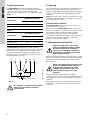
All three-phase Grundfos AP pumps supplied
without control box must be connected to a separate
motor starter. The explosion-proof pumps have a
thermal switch built into the motor windings. The
thermal switch is connected to the control circuit of
the motor starter, see fig. 1.
Fig. 1
6. Start-up
Do not start up the pump until the system has been
filled with liquid and vented. Make sure that the
pump is submerged in the liquid, open the isolating
valves, if fitted, and check the setting of the level
switches.
Note: The pump may, however, be started for a very
short period without being submerged for checking
of the direction of rotation.
6.1 Direction of rotation
All single-phase pumps are factory-set to the
correct direction of rotation.
Before starting up three-phase pumps, check the
direction of rotation. The direction of rotation should
be clockwise when viewed from above. When
starting up, the pump will jerk in the opposite
direction to the direction of rotation. If the direction of
rotation is wrong, interchange two of the three
phases of the electricity supply.
7. Maintenance and service
Before carrying out maintenance and service, make
sure that the pump has been thoroughly flushed with
clean water. Rinse the pump parts in water after
dismantling.
Pumps running normal operation should be
inspected at least once a year. If the pumped liquid is
very muddy or sandy, inspect the pump at shorter
intervals.
When the pump is new or after replacement of the
shaft seals, check the oil level after one week of
operation.
Pump type
Operating capacitor
[µF] [V]
AP51.65.07.1 25 1 x 450
AP51.65.12.1 30 1 x 450
Pump type
Operating capacitor
[µF] [V]
AP51.65.09.1 20 1 x 450
AP51.65.13.1 25 1 x 450
AP51.65.14.1V 25 1 x 450
TM00 1618 0693
The separate control box/motor starter
must not be installed in explosive
environments.
M
Max. 250V / 2.5 A
T1
U
VW
T2
PE
Max. 250 V/2.5 A
Before starting work on the pump,
make sure that the electricity supply
has been switched off and that it
cannot be accidentally switched on.
Furthermore, all rotating parts must
have stopped moving.
When unscrewing the inspection screw
of the oil chamber, please note that
pressure may have built up in the
chamber. Do not remove the screw
until the pressure has been fully
relieved.

English (GB)
9
For long and trouble-free operation of the pump the
following points should be checked regularly:
• Power consumption
• Oil level and oil condition
The oil becomes greyish white like milk if it
contains water. This may be the result of a
defective shaft seal. The oil should be replaced
after 3000 hours of operation.
Use Shell Ondina 15 oil or similar type.
Note: Used oil must be disposed of in
accordance with local regulations.
The following table states how much oil the
AP pumps must have in the stator housing and
the oil chamber:
Ex = explosion-proof.
• Cable entry
Make sure that the cable entry is watertight and
that the cables are not bent sharply and/or
pinched.
• Pump parts
Check the impeller, pump housing, neck ring, etc.
for possible wear. Replace defective parts.
• Ball bearings
Check the shaft for noisy or heavy operation
(turn the shaft by hand). Replace defective ball
bearings.
A general overhaul of the pump is usually
required in case of defective ball bearings or poor
motor function. This work must be carried out by
the manufacturer or a competent workshop.
7.1 Contaminated pumps
Note: If a pump has been used for a liquid which is
injurious to health or toxic, the pump will be
classified as contaminated.
If Grundfos is requested to service the pump,
Grundfos must be contacted with details about the
pumped liquid, etc. before the pump is returned for
service. Otherwise Grundfos can refuse to accept
the pump for service.
Possible costs of returning the pump are paid by the
customer.
However, any application for service (no matter to
whom it may be made) must include details about
the pumped liquid if the pump has been used for
liquids which are injurious to health or toxic.
Pump type
Quantity of oil in:
Stator
housing
Oil
chamber
AP51.65.07 0.01 l
AP51.65.09 0.01 l
AP51.65.12 0.01 l
AP51.65.13 0.01 l
AP51.65.14 0.01 l
AP51.65.14V 0.01 l
AP51.65.15 0.01 l
AP51.65.15V 0.01 l
AP51.65.17 1.20 l
AP51.65.22 0.60 l 1.20 l
AP51.65.22.3(Ex) 1.20 l
AP51.65.23 0.60 l 1.20 l
AP51.65.23V 0.60 l 1.20 l
AP51.65.34 0.60 l 1.20 l
AP51.65.34V 0.60 l 1.20 l
AP51.65.35 0.60 l 1.20 l
AP51.65.35V 0.60 l 1.20 l
AP51.65.36V 0.60 l 1.20 l

English (GB)
10
8. Fault finding chart
9. Disposal
This product or parts of it must be disposed of in an
environmentally sound way:
1. Use the public or private waste collection service.
2. If this is not possible, contact the nearest
Grundfos company or service workshop.
Subject to alterations.
Make sure that all power supplies have been switched off and that all rotating parts have
stopped moving before attempting to diagnose any fault.
Fault Cause Remedy
1. Motor does not start. Fuses
blow or motor starter trips out
immediately.
Caution: Do not start again!
a) Supply failure; short-circuit;
earth-leakage fault in cable or
motor winding.
Have the cable and motor checked
and repaired by a qualified
electrician.
b) Fuses blow due to use of
wrong type of fuse.
Install fuses of the correct type.
c) Impeller blocked by impurities. Clean the impeller.
d) Level switch out of adjustment
or defective.
Check the level switch.
2. Pump operates, but motor
starter trips out after a short
while.
a) Low setting of thermal relay in
motor starter.
Set the relay in accordance with
the specifications on the
nameplate.
b) Increased current
consumption due to large
voltage drop.
Measure the voltage between
motor phases. Tolerance: ± 10 %.
c) Impeller blocked by impurities.
Increased current
consumption in all three
phases.
Clean the impeller.
3. Pump operates at
below-standard performance
and power consumption.
a) Impeller blocked by impurities. Clean the impeller.
Check the direction of rotation and
possibly interchange two phases,
see section 6.1 Direction of
rotation.
b) Wrong direction of rotation.
4. Pump operates, but gives no
liquid.
a) Discharge valve closed or
blocked.
Check discharge valve and
possibly open and/or clean.
b) Non-return valve blocked. Clean non-return valve.
Vent the pump.c) Air in pump.

Appendix
62
Appendix 1
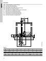
GB: 1-pump installation on auto-coupling
DK: En pumpe med auto-kobling
DE: Eine Pumpe mit Autokupplung
GR: Εγκατάσταση μιάς αντλίας με αυτόματη ζεύξη
ES: Una bomba con autoacoplamiento
FR: Une pompe avec système d’accouplement automatique
IT: Una pompa con accoppiamento rapido
NL: Eén pomp met voetbochtsnelkoppeling
PT: Uma bomba com acoplamento automático
FI: Yhden pumpun asennus jalustaliittimellä
SE: En pump installerad med kopplingsfot
Fig. A
TM01 2565 2098
‹
‹
‹
‹
‹
‹
‹
‹
‹
‹
‹‹
‹
‹
‹
‹
‹
‹
‹
‹
‹
‹
‹
‹
‹
‹
‹
‹
‹
‹
‹
‹
‹
‹
‹
‹
‹
‹
‹
‹
‹
‹
‹
‹
‹
‹
‹
‹
‹
‹
‹
‹
‹
‹
‹
‹
‹
‹
‹
‹
‹
‹
‹
‹
‹
‹
‹
‹
‹
‹
‹
‹
‹
‹
‹
‹
‹
‹
‹
‹
‹
‹
‹
‹
‹
‹
‹
‹
‹
‹
‹
‹
‹
‹
‹
‹
‹
‹
‹
‹
‹
‹
‹
‹
‹
‹
‹
‹
‹
‹
‹
‹
‹
‹
‹
‹
‹
‹
‹
‹
‹
‹
‹
‹
‹
‹
‹
‹
‹
‹
‹
‹
‹
‹
‹
‹
‹
‹
‹
‹
‹
‹
‹
‹
‹
‹
‹
‹
‹
‹
‹
‹
‹
‹
‹
‹
‹
‹
‹
‹
‹
‹
‹
‹
‹
‹
‹
‹
‹
‹
‹
‹
‹
‹
‹
‹
‹
‹
‹
‹
‹
‹
‹
‹
‹
‹
‹
‹
‹
‹
‹
‹
‹
‹
‹
‹
‹
‹
‹
‹
‹
‹
‹
‹
‹
‹
‹
‹
‹
‹
‹
‹
‹
‹
‹
‹
‹
‹
‹
‹
‹
‹
‹
‹
‹
‹
‹
‹
‹
‹
‹
‹
‹
‹
‹
‹
‹
‹
K
G
H
L
N O
F
C
A
U
V
J
S
A B C D E F G H I J
∅600 ∅600 300 300 70 60 82 68 180 85
K L M N O P R S T U V
150 410 220 350 650 500 - DN65 1" 140 240

Appendix
63
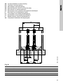
GB: 2-pump installation on auto-coupling
DK: To pumper med auto-kobling
DE: Zwei Pumpen mit Autokupplung
GR: Εγκατάσταση δύο αντλιών με αυτόματη ζεύξη
ES: Dos bombas con autoacoplamiento
FR: Deux pompes avec système d’accouplement automatique
IT: Due pompe con accoppiamento rapido
NL: Tvee pompen met voetbochtsnelkoppeling
PT: Duas bombas com acoplamento automático
FI: Kahden pumpun asennus jalustaliittimellä
SE: Två pumpar installerade med kopplingsfot
Fig. B
TM01 2566 2098
‹
‹
‹
‹
‹
‹
‹
‹
‹
‹
‹
‹
‹
‹
‹
‹
‹
‹
‹
‹
‹
‹
‹
‹
‹
‹
‹
‹
‹
‹
‹
‹
‹
‹
‹
‹
‹
‹
‹
‹
‹
‹
‹
‹
‹
‹
‹
‹
‹
‹
‹
‹
‹
‹
‹
‹
‹
‹
‹
‹
‹
‹
‹
‹
‹
‹
‹
‹
‹
‹
‹
‹
‹
‹
‹
‹
‹
‹
‹
‹
‹
‹
‹
‹
‹
‹
‹
‹
‹
RP P
MM
I
B
D
A B C D E F G H I
600 975 300 297 70 60 82 68 180
K L M N O P R S T U V
150 410 220 375 875 435 380 DN65 1" 140 240

Appendix
64
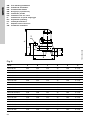
GB: Free-standing Installation
DK: Fritstående installation
DE: Freistehender Einbau
GR: Ανεξάρτητη εγκατάσταση
ES: Instalación portátil
FR: Installation fixe sur socle
IT: Installazione su piede d’appoggio
NL: Vrijstaande opstelling
PT: Instalação autónoma
FI: Vapaasti seisova asennus
SE: Fristående installation
Fig. C
TM01 2564 2098
S
E
C
D
B
A
AP51 A B C D E S
AP51.65.07 465 350 110 55 198 R 2 1/2
AP51.65.09 448 350 110 55 198 R 2 1/2
AP51.65.12 465 350 110 55 198 R 2 1/2
AP51.65.13 448 350 110 55 198 R 2 1/2
AP51.65.14 448 350 110 55 198 R 2 1/2
AP51.65.14V 448 350 110 55 198 R 2 1/2
AP51.65.15 448 350 110 55 198 R 2 1/2
AP51.65.15V 558 368 101 55 189 R 2 1/2
AP51.65.17 518 368 101 55 189 R 2 1/2
AP51.65.22 558 368 101 55 189 R 2 1/2
AP51.65.22.3(Ex) 518 368 101 55 189 R 2 1/2
AP51.65.23 558 368 101 55 189 R 2 1/2
AP51.65.23V 558 368 101 55 189 R 2 1/2
AP51.65.34 558 368 101 55 189 R 2 1/2
AP51.65.34V 558 368 101 55 189 R 2 1/2
AP51.65.35 558 368 101 55 189 R 2 1/2
AP51.65.35V 558 368 101 55 189 R 2 1/2
AP51.65.36V 558 368 101 55 189 R 2 1/2

Grundfos companies
Argentina
Bombas GRUNDFOS de Argentina S.A.
Ruta Panamericana km. 37.500 Lote
34A
1619 - Garin
Pcia. de Buenos Aires
Phone: +54-3327 414 444
Telefax: +54-3327 411 111
Australia
GRUNDFOS Pumps Pty. Ltd.
P.O. Box 2040
Regency Park
South Australia 5942
Phone: +61-8-8461-4611
Telefax: +61-8-8340 0155
Austria
GRUNDFOS Pumpen Vertrieb
Ges.m.b.H.
Grundfosstraße 2
A-5082 Grödig/Salzburg
Tel.: +43-6246-883-0
Telefax: +43-6246-883-30
Belgium
N.V. GRUNDFOS Bellux S.A.
Boomsesteenweg 81-83
B-2630 Aartselaar
Tél.: +32-3-870 7300
Télécopie: +32-3-870 7301
Belorussia
Представительство ГРУНДФОС в
Минске
220123, Минск,
ул. В. Хоружей, 22, оф. 1105
Тел.: +(37517) 233 97 65,
Факс: +(37517) 233 97 69
E-mail: grundfos_m[email protected]
Bosnia/Herzegovina
GRUNDFOS Sarajevo
Trg Heroja 16,
BiH-71000 Sarajevo
Phone: +387 33 713 290
Telefax: +387 33 659 079
e-mail: grundfos@bih.net.ba
Brazil
BOMBAS GRUNDFOS DO BRASIL
Av. Humberto de Alencar Castelo
Branco, 630
CEP 09850 - 300
São Bernardo do Campo - SP
Phone: +55-11 4393 5533
Telefax: +55-11 4343 5015
Bulgaria
Grundfos Bulgaria EOOD
Slatina District
Iztochna Tangenta street no. 100
BG - 1592 Sofia
Tel. +359 2 49 22 200
Fax. +359 2 49 22 201
email: bulgaria@grundfos.bg
Canada
GRUNDFOS Canada Inc.
2941 Brighton Road
Oakville, Ontario
L6H 6C9
Phone: +1-905 829 9533
Telefax: +1-905 829 9512
China
GRUNDFOS Pumps (Shanghai) Co. Ltd.
50/F Maxdo Center No. 8 XingYi Rd.
Hongqiao development Zone
Shanghai 200336
PRC
Phone: +86-021-612 252 22
Telefax: +86-021-612 253 33
Croatia
GRUNDFOS CROATIA d.o.o.
Cebini 37, Buzin
HR-10010 Zagreb
Phone: +385 1 6595 400
Telefax: +385 1 6595 499
www.grundfos.hr
Czech Republic
GRUNDFOS s.r.o.
Čajkovského 21
779 00 Olomouc
Phone: +420-585-716 111
Telefax: +420-585-716 299
Denmark
GRUNDFOS DK A/S
Martin Bachs Vej 3
DK-8850 Bjerringbro
Tlf.: +45-87 50 50 50
Telefax: +45-87 50 51 51
E-mail: [email protected]
www.grundfos.com/DK
Estonia
GRUNDFOS Pumps Eesti OÜ
Peterburi tee 92G
11415 Tallinn
Tel: + 372 606 1690
Fax: + 372 606 1691
Finland
OY GRUNDFOS Pumput AB
Mestarintie 11
FIN-01730 Vantaa
Phone: +358-3066 5650
Telefax: +358-3066 56550
France
Pompes GRUNDFOS Distribution S.A.
Parc d’Activités de Chesnes
57, rue de Malacombe
F-38290 St. Quentin Fallavier (Lyon)
Tél.: +33-4 74 82 15 15
Télécopie: +33-4 74 94 10 51
Germany
GRUNDFOS GMBH
Schlüterstr. 33
40699 Erkrath
Tel.: +49-(0) 211 929 69-0
Telefax: +49-(0) 211 929 69-3799
e-mail: infoservice@grundfos.de
Service in Deutschland:
e-mail: kundendienst@grundfos.de
Greece
GRUNDFOS Hellas A.E.B.E.
20th km. Athinon-Markopoulou Av.
P.O. Box 71
GR-19002 Peania
Phone: +0030-210-66 83 400
Telefax: +0030-210-66 46 273
Hong Kong
GRUNDFOS Pumps (Hong Kong) Ltd.
Unit 1, Ground floor
Siu Wai Industrial Centre
29-33 Wing Hong Street &
68 King Lam Street, Cheung Sha Wan
Kowloon
Phone: +852-27861706 / 27861741
Telefax: +852-27858664
Hungary
GRUNDFOS Hungária Kft.
Park u. 8
H-2045 Törökbálint,
Phone: +36-23 511 110
Telefax: +36-23 511 111
India
GRUNDFOS Pumps India Private Lim-
ited
118 Old Mahabalipuram Road
Thoraipakkam
Chennai 600 096
Phone: +91-44 2496 6800
Indonesia
PT GRUNDFOS Pompa
Jl. Rawa Sumur III, Blok III / CC-1
Kawasan Industri, Pulogadung
Jakarta 13930
Phone: +62-21-460 6909
Telefax: +62-21-460 6910 / 460 6901
Ireland
GRUNDFOS (Ireland) Ltd.
Unit A, Merrywell Business Park
Ballymount Road Lower
Dublin 12
Phone: +353-1-4089 800
Telefax: +353-1-4089 830
Italy
GRUNDFOS Pompe Italia S.r.l.
Via Gran Sasso 4
I-20060 Truccazzano (Milano)
Tel.: +39-02-95838112
Telefax: +39-02-95309290 / 95838461
Japan
GRUNDFOS Pumps K.K.
Gotanda Metalion Bldg., 5F,
5-21-15, Higashi-gotanda
Shiagawa-ku, Tokyo
141-0022 Japan
Phone: +81 35 448 1391
Telefax: +81 35 448 9619
Korea
GRUNDFOS Pumps Korea Ltd.
6th Floor, Aju Building 679-5
Yeoksam-dong, Kangnam-ku, 135-916
Seoul, Korea
Phone: +82-2-5317 600
Telefax: +82-2-5633 725
Latvia
SIA GRUNDFOS Pumps Latvia
Deglava biznesa centrs
Augusta Deglava ielā 60, LV-1035, Rīga,
Tālr.: + 371 714 9640, 7 149 641
Fakss: + 371 914 9646
Lithuania
GRUNDFOS Pumps UAB
Smolensko g. 6
LT-03201 Vilnius
Tel: + 370 52 395 430
Fax: + 370 52 395 431

Grundfos companies
Malaysia
GRUNDFOS Pumps Sdn. Bhd.
7 Jalan Peguam U1/25
Glenmarie Industrial Park
40150 Shah Alam
Selangor
Phone: +60-3-5569 2922
Telefax: +60-3-5569 2866
México
Bombas GRUNDFOS de México S.A. de
C.V.
Boulevard TLC No. 15
Parque Industrial Stiva Aeropuerto
Apodaca, N.L. 66600
Phone: +52-81-8144 4000
Telefax: +52-81-8144 4010
Netherlands
GRUNDFOS Netherlands
Veluwezoom 35
1326 AE Almere
Postbus 22015
1302 CA ALMERE
Tel.: +31-88-478 6336
Telefax: +31-88-478 6332
E-mail: info_gnl@grundfos.com
New Zealand
GRUNDFOS Pumps NZ Ltd.
17 Beatrice Tinsley Crescent
North Harbour Industrial Estate
Albany, Auckland
Phone: +64-9-415 3240
Telefax: +64-9-415 3250
Norway
GRUNDFOS Pumper A/S
Strømsveien 344
Postboks 235, Leirdal
N-1011 Oslo
Tlf.: +47-22 90 47 00
Telefax: +47-22 32 21 50
Poland
GRUNDFOS Pompy Sp. z o.o.
ul. Klonowa 23
Baranowo k. Poznania
PL-62-081 Przeźmierowo
Tel: (+48-61) 650 13 00
Fax: (+48-61) 650 13 50
Portugal
Bombas GRUNDFOS Portugal, S.A.
Rua Calvet de Magalhães, 241
Apartado 1079
P-2770-153 Paço de Arcos
Tel.: +351-21-440 76 00
Telefax: +351-21-440 76 90
România
GRUNDFOS Pompe România SRL
Bd. Biruintei, nr 103
Pantelimon county Ilfov
Phone: +40 21 200 4100
Telefax: +40 21 200 4101
E-mail: romania@grundfos.ro
Russia
ООО Грундфос
Россия, 109544 Москва, ул. Школьная
39
Тел. (+7) 495 737 30 00, 564 88 00
Факс (+7) 495 737 75 36, 564 88 11
E-mail grundfos.moscow@grundfos.com
Serbia
GRUNDFOS Predstavništvo Beograd
Dr. Milutina Ivkovića 2a/29
YU-11000 Beograd
Phone: +381 11 26 47 877 / 11 26 47
496
Telefax: +381 11 26 48 340
Singapore
GRUNDFOS (Singapore) Pte. Ltd.
24 Tuas West Road
Jurong Town
Singapore 638381
Phone: +65-6865 1222
Telefax: +65-6861 8402
Slovenia
GRUNDFOS d.o.o.
Šlandrova 8b, SI-1231 Ljubljana-Črnuče
Phone: +386 1 568 0610
Telefax: +386 1 568 0619
E-mail: [email protected]
South Africa
Corner Mountjoy and George Allen
Roads
Wilbart Ext. 2
Bedfordview 2008
Phone: (+27) 11 579 4800
Fax: (+27) 11 455 6066
E-mail: lsmart@grundfos.com
Spain
Bombas GRUNDFOS España S.A.
Camino de la Fuentecilla, s/n
E-28110 Algete (Madrid)
Tel.: +34-91-848 8800
Telefax: +34-91-628 0465
Sweden
GRUNDFOS AB
Box 333 (Lunnagårdsgatan 6)
431 24 Mölndal
Tel.: +46(0)771-32 23 00
Telefax: +46(0)31-331 94 60
Switzerland
GRUNDFOS Pumpen AG
Bruggacherstrasse 10
CH-8117 Fällanden/ZH
Tel.: +41-1-806 8111
Telefax: +41-1-806 8115
Taiwan
GRUNDFOS Pumps (Taiwan) Ltd.
7 Floor, 219 Min-Chuan Road
Taichung, Taiwan, R.O.C.
Phone: +886-4-2305 0868
Telefax: +886-4-2305 0878
Thailand
GRUNDFOS (Thailand) Ltd.
92 Chaloem Phrakiat Rama 9 Road,
Dokmai, Pravej, Bangkok 10250
Phone: +66-2-725 8999
Telefax: +66-2-725 8998
Turkey
GRUNDFOS POMPA San. ve Tic. Ltd.
Sti.
Gebze Organize Sanayi Bölgesi
Ihsan dede Caddesi,
2. yol 200. Sokak No. 204
41490 Gebze/ Kocaeli
Phone: +90 - 262-679 7979
Telefax: +90 - 262-679 7905
E-mail: satis@grundfos.com
Ukraine
ТОВ ГРУНДФОС УКРАЇНА
01010 Київ, Вул. Московська 8б,
Тел.:(+38 044) 390 40 50
Фах.: (+38 044) 390 40 59
E-mail: ukraine@grundfos.com
United Arab Emirates
GRUNDFOS Gulf Distribution
P.O. Box 16768
Jebel Ali Free Zone
Dubai
Phone: +971-4- 8815 166
Telefax: +971-4-8815 136
United Kingdom
GRUNDFOS Pumps Ltd.
Grovebury Road
Leighton Buzzard/Beds. LU7 8TL
Phone: +44-1525-850000
Telefax: +44-1525-850011
U.S.A.
GRUNDFOS Pumps Corporation
17100 West 118th Terrace
Olathe, Kansas 66061
Phone: +1-913-227-3400
Telefax: +1-913-227-3500
Usbekistan
Представительство ГРУНДФОС в
Ташкенте
700000 Ташкент ул.Усмана Носира 1-й
тупик 5
Телефон: (3712) 55-68-15
Факс: (3712) 53-36-35
Revised 29.09.2010

www.grundfos.com
Being responsible is our foundation
Thinking ahead makes it possible
Innovation is the essence
The name Grundfos, the Grundfos logo, and the payoff Be–Think–Innovate are registrated trademarks
owned by Grundfos Management A/S or Grundfos A/S, Denmark. All rights reserved worldwide.
96434819 0911
Repl. 96434819 0902
ECM: 1078667
-
 1
1
-
 2
2
-
 3
3
-
 4
4
-
 5
5
-
 6
6
-
 7
7
-
 8
8
-
 9
9
-
 10
10
-
 11
11
-
 12
12
-
 13
13
-
 14
14
-
 15
15
-
 16
16


Grundfos AP51,65.36V Installation And Operating Instructions Manual
- Typ
- Installation And Operating Instructions Manual
in anderen Sprachen
- English: Grundfos AP51,65.36V
Verwandte Artikel
-
Grundfos CU 100 Installation And Operating Instructions Manual
-
-
Grundfos Unilift KP 250 Installation And Operating Instructions Manual
-
Grundfos CH Series Installation And Operating Instructions Manual
-
-
-
-
-
Grundfos DMS 8 Installation And Operating Instructions Manual
-
