
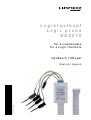
Logiktastkopf
Logic probe
HO2010
für 4 Logikkanäle
for 4 Logic channels
Handbuch / Manual
Deutsch / English
46-2010-0010

HO2010 Logic probe
Specifi cations
Channels: 4
Input impedance: 100 kΩ II <4pF
Max. Input voltage: 40 V (DC + peak AC)
Measuring Category: I
Cable length: approx. 1 m
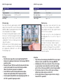
References
The logic probe can be attached to the male
connector at the frontpanel of the HM2008.
Only in digital mode four logic signal channels
(LC0 to LC3) are available.
The logic levels of the connected signals will
be displayed at the screen of the scope in 1
bit form.
The threshold can be adjusted in the menu „Lo-
gic Chann.“ for all logic channels together.
Within the menu, the logic channels can be
switched on or off, by push the key LC/AUX.
The active logic channel will be indicate by an
LED on the probe.
Attention
– Only with an attached logic probe HO2010 the logic signal
channels can be used with the oscilloscope HM2008.
– Individual pins of the male connector at the oscilloscope
are galvanically connected with all electrically leading
parts of the oscilloscope and (Net-) protective grounding!
– On the male connector at the oscilloscope no voltages
without logic probe may be set directly!
– On the logic probe no voltages may be set more largely
than 40 V (DC + peak AC)!
HO2010 Logiktastkopf
Technische Daten
Kanäle: 4
Eingangsimpedanz: 100 kΩ II <4pF
Max. Eingangsspannung: 40 V (DC + peak AC)
Messkategorie: I
Kabellänge: ca. 1 m
Erläuterung
Nach Anschluss des Logiktastkopfes HO2010
an die frontseitige Stiftleiste des Oszilloskops
HM2008 sind die 4 Logiksignal-Kanäle (LC0 bis
LC3) im Digitalbetrieb verfügbar.
Die Pegel der anliegenden Signale werden in
Form einer 1-Bit Darstellung am Oszilloskop
angezeigt. Die Schaltschwelle kann im Menü
„Logikkanäle“ für alle 4 Kanäle gemeinsam
eingestellt werden.
Im Menü der Taste LC/AUX werden die Logik-
kanäle ein- und ausgeschaltet. Die Aktivierung
der Logikkanäle wird durch eine LED am
Tastkopf angezeigt.
Achtung
– Nur mit einem angeschlossenen Logiktastkopf HO2010
können die Logiksignal-Kanäle des Oszilloskopes HM2008
genutzt werden.
– Einzelne Pins der Stiftleiste am Oszilloskop sind mit allen
elektrisch leitenden Teilen des Oszilloskops und dem
(Netz-) Schutzleiter galvanisch verbunden!
– An die Stiftleiste am Oszilloskop dürfen keine Span-
nungen ohne Logiktastkopf direkt angelegt werden!
– An den Logiktastkopf dürfen keine Spannungen größer als
40 V (DC + peak AC) angelegt werden!

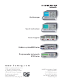
Oscilloscopes
Spectrum Analyzer
Power Supplies
Modular system 8000 Series
Programmable Instruments
8100 Series
www.hameg.com
Subject to change without notice
17-09-2007 / 46-2010-0010 HAMEG Instruments GmbH
© HAMEG Instruments GmbH Industriestraße 6
A Rohde & Schwarz Company D-63533 Mainhausen
® registered trademark Tel +49 (0) 61 82 800-0
DQS-Certifi cation: Fax +49 (0) 61 82 800-100
DIN EN ISO 9001:2000, Reg.-Nr.: 071040 QM [email protected]
-
 1
1
-
 2
2
-
 3
3


