AKG C 900-TM 40 Bedienungsanleitung
- Kategorie
- Mikrofone
- Typ
- Bedienungsanleitung
Dieses Handbuch eignet sich auch für

Bedienungsanleitung . . . . . . . . . . . . S. 2
Bitte vor Inbetriebnahme des Gerätes lesen!
User Instructions . . . . . . . . . . . . . . p. 12
Please read the manual before using the equipment!
Mode d’emploi . . . . . . . . . . . . . . . . p. 22
Veuillez lire cette notice avant d’utiliser le système!
Istruzioni per l’uso . . . . . . . . . . . . . p. 32
Prima di utilizzare l’apparecchio, leggere il manuale
Modo de empleo . . . . . . . . . . . . . . . p. 42
¡Sirvase leer el manual antes de utilizar el equipo!
Instruções de uso . . . . . . . . . . . . . . p. 52
Por favor leia este manual antes de usar o equipamento!
C 900
M
C 900
M
/TM 40
3511_C900M_fsch.qxd 12.07.2006 20:24 Uhr Seite 1

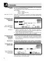
Überprüfen Sie bitte, ob das Gerät, an das Sie das Mikrofon
anschließen möchten, den gültigen Sicherheitsbestimmungen
entspricht und mit einer Sicherheitserdung versehen ist.
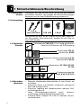
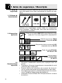
Kontrollieren Sie bitte, ob die Verpackung alle oben angeführ-
ten Teile enthält. Falls etwas fehlt, wenden Sie sich bitte an
Ihren AKG-Händler.
• Robustes Kondensator-Vokalmikrofon für den Einsatz auf
der Bühne
• Integriertes Wind- und Popfilter unterdrückt wirkungsvoll
Pop- und Atemgeräusche
• Elastische Lagerung des Wandlersystems reduziert Griff-
und Kabelgeräusche
• Hohe Rückkopplungssicherheit durch frequenz-
unabhängige nierenförmige Richtcharakteristik
• Presence Boost Adapter PB 1000 für optimale Sprach-
verständlichkeit
1.1 Sicherheits-
hinweis
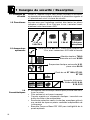
1.2 Lieferumfang
1.3 Optionales
Zubehör
1.4 Besondere
Merkmale
2
1 Sicherheitshinweis/Beschreibung
• Mikrofonkabel MK 9/10: 10 m 2-polig geschirmtes
Kabel mit XLR-Stecker und XLR-Kupplung
• Sendermodul TM 40,
• Windschutz W 880
• Elastische Universal-Aufhängung H 30,
Stativanschluss SA 26
• Bodenstative ST 102A, ST 200,
ST 305
• Phantomspeisegeräte
N 62, N 66, B 18, B 15
1 C 900
M
oder C 900
M
/TM 40
1 PB 1000 1 SA 61 1 Etui
3511_C900M_fsch.qxd 12.07.2006 20:24 Uhr Seite 2

1.5 C 900
M
,
C 900
M
/TM 40
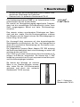
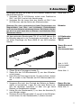
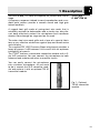
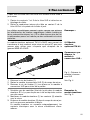
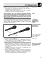
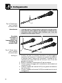
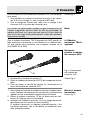
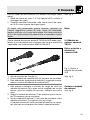
Abb. 1: Optionales
Sendermodul TM 40
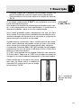
• Sicherer Schutz des Mikrofonwandlers durch nahezu unde-
formierbare Gitterkappe aus Federstahl
• Einbauschacht für optionales Sendermodul TM 40
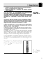
Das Kondensatormikrofon C 900
M
ist ein Vokalmikrofon für den
professionellen Einsatz auf der Bühne.
Der speziell auf Gesangsübertragung abgestimmte Frequenz-
gang und die nierenförmige Richtcharakteristik bieten Ihnen
einen ausgewogenen Sound und hohe Rückkopplungs-
sicherheit.
Eine robuste, nahezu unverformbare Gitterkappe aus Feder-
stahl und das stabile Zink-Alu-Druckgussgehäuse schützen
das Mikrofon und die Kapsel wirksam vor Beschädigungen im
harten Alltag "on the road".
Der Aussengrill dient zusammen mit dem darunterliegenden
Spezialgewebe als Windschutz, der Pop- und Atemgeräusche
sowie eine unnatürliche Überbetonung von Zischlauten zuver-
lässig ausschaltet.
Der mitgelieferte Presence Boost Adapter PB 1000 optimiert
die Sprachverständlichkeit durch eine Anhebung um etwa 5 dB
zwischen 5 kHz und 9 kHz.
Das C 900
M
ist mit einem abnehmbaren Anschlussmodul mit 3-
poligem XLR-Stecker ausgestattet. Sie können das C 900
M
sowohl an symmetrischen als auch asymmetrischen Mischpult-
und Verstärkereingängen betreiben.
Sie können das Mikrofon auf einfache
Weise in ein Drahtlos-Mikrofon umwan-
deln, indem Sie das XLR-Steckermodul
ausbauen und durch das optionale
Sendermodul TM 40 ersetzen.
1 Beschreibung
3
3511_C900M_fsch.qxd 12.07.2006 20:24 Uhr Seite 3

2.1 Allgemeines
Siehe Kapitel 2.2
und 2.3.
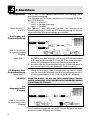
2.2 Eingang mit
Phantomspeisung
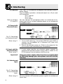
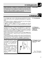
Abb. 2: Anschluss
an symmetrischen
Eingang
Siehe Abb. 2.
2.3 Eingang ohne
Phantomspeisung
Siehe Abb. 2.
Wichtig!
2.4
Asymmetrischer
Eingang
Abb. 3: Anschluss
an asymmetrischen
Eingang
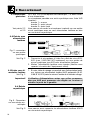
Das C 900
M
ist ein Kondensatormikrofon und benötigt daher
eine Stromversorgung.
Das Mikrofon besitzt einen symmetrischen Ausgang mit 3-poli-
gem XLR-Stecker:
Stift 1 = Masse
Stift 2 = Tonader (inphase)
Stift 3 = Tonader
Sie können das Mikrofon sowohl an symmetrische
Mikrofoneingänge mit oder ohne Phantomspeisung als auch an
asymmetrische Mikrofoneingänge anschließen.
1. Schließen Sie das Mikrofon mit einem XLR-Mikrofonkabel
(z.B. dem optionalen MK 9/10 von AKG) an einen symmetri-
schen XLR-Mikrofoneingang mit Phantomspeisung an.
2. Schalten Sie die Phantomspeisung ein. (Lesen Sie dazu in
der Betriebsanleitung des jeweiligen Gerätes nach.)
1. Wenn Ihr Mischpult keine Phantomspeisung besitzt, schal-
ten Sie zwischen Mikrofon und Mischpulteingang ein AKG-
Phantomspeisegerät (N 62, N 66, B 18, B 15 - optional).
Wenn Sie andere als die von AKG empfohlenen Speise-
geräte verwenden, kann das Mikrofon beschädigt werden
und erlischt die Garantie.
Die Phantomspeisegeräte von AKG können Sie auch an einen
asymmetrischen Eingang anschließen.
4
2 Anschluss
2.2
2.3
C 900
M
C 900
M
Phantom
C 900
M
Phantom
3511_C900M_fsch.qxd 12.07.2006 20:24 Uhr Seite 4

Siehe Abb. 3.
Hinweis:
2.5 Optionales
Sendermodul
TM 40
Bauen Sie zuerst
das XLR-
Steckermodul aus:
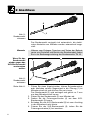
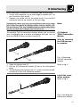
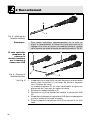
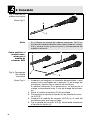
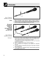
Abb. 4: XLR-
Steckermodul
ausbauen
Siehe Abb. 4.
Bauen Sie das
Sendermodul ein:
Siehe Abb. 5.
Verwenden Sie dazu ein Kabel mit XLR-Stecker (weiblich) und
Mono-Klinkenstecker:
1. Verbinden Sie im XLR-Stecker mittels einer Drahtbrücke
Stift 1 mit Stift 3 und mit der Abschirmung.
2. Verbinden Sie die innere Ader des Kabels mit Stift 2 des
XLR-Steckers und der Spitze des Klinkensteckers.
Beachten Sie, dass asymmetrische Kabel Einstreuungen aus
Magnetfeldern (von Netz- und Lichtkabeln, Elektromotoren
usw.) wie eine Antenne aufnehmen können. Bei Kabeln, die län-
ger als 5 m sind, kann dies zu Brumm- und ähnlichen Stör-
geräuschen führen.
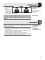
Mit dem optionalen Sendermodul TM 40 von AKG können Sie
Ihr Mikrofon jederzeit in ein Funkmikrofon verwandeln, das Sie
mit jedem Empfänger der Serie WMS 40 von AKG betreiben
können.
1. Öffnen Sie die Fixierungsschraube (1).
2. Ziehen Sie das XLR-Steckermodul (2) aus dem Mikrofon-
schaft heraus.
3. Damit Sie die Fixierungsschraube (1) nicht verlieren, drehen
Sie sie wieder in das Gewinde am XLR-Steckermodul hin-
ein.
1. Vergessen Sie nicht, den Zustand der Batterie im Sender-
modul zu kontrollieren. Legen Sie eine neue Batterie ein,
falls die derzeitige verbraucht ist oder sich gar keine
Batterie im Sendermodul befindet.
2. Halten Sie das Sendermodul (1) so, dass die Kontakte (2)
zum Mikrofon zeigen.
3. Schieben Sie das Sendermodul (1) so weit in den Mikrofon-
schaft hinein, bis das Sendermodul (1) hörbar einrastet.
2 Anschluss
5
1
2
3511_C900M_fsch.qxd 12.07.2006 20:24 Uhr Seite 5

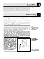
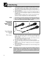
Abb. 5:
Sendermodul
einbauen
Hinweis:
Wenn Sie das
Sendermodul
wieder gegen das
XLR-Steckermodul
austauschen
wollen:
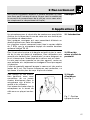
Abb. 6:
Sendermodul
ausbauen
Siehe Abb. 6.
Das Sendermodul verriegelt sich automatisch, die elektri-
schen Kontakte zum Mikrofon werden automatisch herge-
stellt.
Näheres zum Einlegen, Tauschen und Testen der Batterie
sowie zum Einstellen und Betrieb des Sendermoduls finden
Sie in der Bedienungsanleitung des Sendermoduls TM 40.
1. Führen Sie einen Kugelschreiber, kleinen Schraubenzieher
oder ähnlichen spitzen Gegenstand in die Öffnung (1) im
Mikrofonschaft ein und drücken Sie nach innen.
Das Sendermodul (2) wird entriegelt und gleitet ca. 2 mm
aus dem Mikrofonschaft heraus.
2. Ziehen Sie das Sendermodul (2) vom Mikrofon ab.
3. Drehen Sie die Fixierungsschraube (4) aus dem XLR-
Steckermodul (3) heraus.
4. Schieben Sie das XLR-Steckermodul (3) bis zum Anschlag
in den Mikrofonschacht hinein.
5. Fixieren Sie das XLR-Steckermodul (3), indem Sie die
Fixierungsschraube (4) fest anziehen.
2 Anschluss
6
1
2
4
2
1
3
3511_C900M_fsch.qxd 12.07.2006 20:24 Uhr Seite 6

Hinweis:
3.1 Einleitung
3.2
Besprechungs-
abstand und
Naheffekt
3.3 Schall-
einfallswinkel
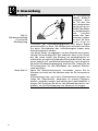
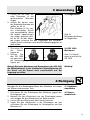
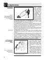
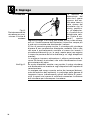
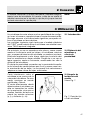
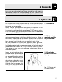
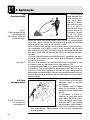
Siehe Abb. 7.
Abb. 7: Typische
Mikrofonposition
Sie können das Sendermodul auch ausbauen, indem Sie das
Sendermodul einfach nur kräftig aus dem Mikrofon heraus-
ziehen. Achten Sie darauf, das Sendermodul dabei nicht am
Batteriefachdeckel anzufassen. (Sie würden sonst lediglich das
Batteriefach öffnen.)
Ein Gesangsmikrofon bietet Ihnen viele Möglichkeiten, den
Klang Ihrer Stimme, wie er durch die Beschallungsanlage wie-
dergegeben wird, zu gestalten.
Beachten Sie bitte die folgenden Hinweise, um Ihr Mikrofon
optimal einsetzen zu können.
Die folgenden Kapitel gelten sowohl für die kabelgebundene
Ausführung des C 900
M
als auch für das Mikrofon mit einge-
bautem optionalem Sendermodul TM 40.
Grundsätzlich wird Ihre Stimme umso voller und weicher wie-
dergegeben, je kürzer der Abstand zwischen den Lippen und
dem Mikrofon ist, während bei größerer Mikrofondistanz ein
halligeres, entfernteres Klangbild zustande kommt, da die
Akustik des Raumes mehr zur Geltung kommt.
Sie können daher Ihre Stimme aggressiv, neutral oder einschmei-
chelnd klingen lassen, indem Sie den Mikrofonabstand verändern.
Der Neheffekt tritt im unmittelbaren Nahbereich der
Schallquelle (weniger als 5 cm) auf und bewirkt eine starke
Betonung der Tiefen. Er verleiht Ihrer Stimme einen voluminö-
seren, intimen, bassbetonten Klang.
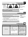
Singen Sie seitlich auf das
Mikrofon oder über den
Mikrofonkopf hinweg. So
erhalten Sie einen ausgewo-
genen, naturgetreuen Klang.
Wenn Sie direkt von vorne auf
das Mikrofon singen, werden
nicht nur Atemgeräusche mit-
übertragen, sondern auch
Verschlusslaute (p, t) und
Zischlaute (s, sch, tsch) un-
natürlich hervorgehoben.
2 Anschluss
7
3 Anwendung
3511_C900M_fsch.qxd 12.07.2006 20:24 Uhr Seite 7

3.4 Rückkopplung
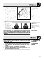
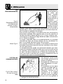
Abb. 8:
Mikrofonaufstellung
für minimale
Rückkopplung
Siehe Abb. 8.
Die Rückkopplung
kommt dadurch
zustande, dass
ein Teil des von
den Lautsprechern
abgegebenen
Schalls vom Mikro-
fon aufgenommen
und verstärkt
wieder den Laut-
sprechern zugelei-
tet wird. Ab einer
bestimmten
Lautstärke (der Rückkopplungsgrenze) läuft dieses Signal
gewissermaßen im Kreis, die Anlage heult und pfeift und kann
nur durch Zurückdrehen des Lautstärkereglers wieder unter
Kontrolle gebracht werden.
Um dieser Gefahr zu begegnen, hat das Mikrofon eine nieren-
förmige Richtcharakteristik. Das bedeutet, dass es für Schall,
der von vorne einfällt (die Stimme) am empfindlichsten ist,
während es auf seitlich einfallenden Schall oder Schall, der von
hinten auftrifft (z.B. von Monitorlautsprechern), kaum anspricht.
Minimale Rückkopplungsneigung erreichen Sie, indem Sie die
PA-Lautsprecher vor den Mikrofonen (am vorderen Bühnen-
rand) aufstellen.
Wenn Sie Monitorlautsprecher verwenden, lassen Sie Ihr
Mikrofon nie direkt auf die Monitore oder die PA-Lautsprecher
zeigen.
Rückkopplung kann auch durch Resonanzerscheinungen (als
Folge der Raumakustik), besonders im unteren Frequenz-
bereich, ausgelöst werden, also indirekt durch den Naheffekt. In
diesem Fall brauchen Sie oft nur den Mikrofonabstand zu ver-
größern, um die Rückkopplung zum Abreissen zu bringen.
3 Anwendung
8
3511_C900M_fsch.qxd 12.07.2006 20:24 Uhr Seite 8

3.5 Begleitchor
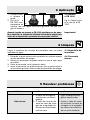
Abb. 9:
Mikrofonaufstellung
für Begleitduo
3.6 PB 1000
Montieren
Abb. 10: Kapsel
ohne (a) und mit (b)
PB 1000
Wichtig!
4.1 Gehäuse-
oberfläche
4.2 Innen-
windschutz
1. Lassen Sie nie mehr als
zwei Personen in ein
gemeinsames Mikrofon
singen.
2. Achten Sie darauf, dass
der Schalleinfallswinkel nie
größer als 35° ist.
Das Mikrofon ist für seit-
lich einfallenden Schall
sehr unempfindlich. Wenn
die beiden VokalistInnen
aus einem größeren Win-
kel als 35° auf das Mikro-
fon singen, müssten Sie den Pegelregler des Mikrofon-
kanals so weit aufziehen, dass die Rückkopplungsgefahr zu
groß würde.
1. Schrauben Sie
die Gitter-
kappe ab.
2. Setzen Sie
den PB 1000
mit einer leich-
ten Drehbewegung bis zum Anschlag auf die Mikrofon-
kapsel auf.
Sichern Sie beim Montieren und Demontieren des PB 1000
die Mikrofonkapsel in der elastischen Gummilagerung mit
der Hand, um die Kapsel nicht versehentlich aus der
Lagerung zu reißen.
Reinigen Sie die Gehäuseoberfläche des Mikrofons mit einem
mit Wasser befeuchteten Tuch.
1. Schrauben Sie die Gitterkappe des Mikrofons gegen den
Uhrzeigersinn ab.
2. Nehmen Sie den Windschutz aus der Gitterkappe heraus
und reinigen Sie den Windschutz mit Seifenwasser.
3. Lassen Sie den Windschutz über Nacht trocknen.
4. Legen Sie den Windschutz in die Gitterkappe ein und
schrauben Sie die Gitterkappe im Uhrzeigersinn auf das
Mikrofon auf.
3 Anwendung
9
4 Reinigung
a
b
3511_C900M_fsch.qxd 12.07.2006 20:24 Uhr Seite 9

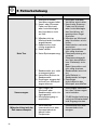
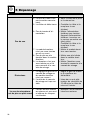
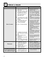
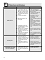
5 Fehlerbehebung
10
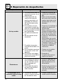
Kein Ton.
Verzerrungen.
Mikrofon klingt mit der
Zeit immer dumpfer.
1. Mischpult und/oder
Verstärker ausgeschaltet.
2. Kanal- oder Summen-
Fader am Mischpult
oder Lautstärkeregler
des Verstärkers steht
auf Null.
3. Mikrofon nicht an
Mischpult oder Verstärker
angeschlossen.
4. Kabelstecker nicht
richtig angesteckt.
5. Kabel defekt.
6. Keine Speisespannung.
7. Sendermodul aus- oder
stummgeschaltet.
8. Keine/leere Batterie im
Sendermodul.
9. Empfänger ausgeschal-
tet/nicht ans Mischpult
angeschlossen.
1. Gain-Regler am
Mischpult oder
Sendermodul nicht rich-
tig eingestellt.
2. Mischpulteingang zu
empfindlich.
• Verschmutzter
Innenwindschutz oder
Aussenwindschutz
dämpft hohe
Frequenzen.
1. Mischpult und/oder
Verstärker einschalten.
2. Kanal-oder Summen-
Fader am Mischpult
oder Lautstärkeregler
des Verstärkers auf
gewünschten Pegel
einstellen.
3. Mikrofon an Mischpult
oder Verstärker ansch-
ließen.
4. Kabelstecker nochmals
anstecken.
5. Kabel überprüfen und
falls nötig ersetzen.
6. Phantomspeisung ein-
schalten.
Phantomspeisegerät:
ans Netz anschließen
bzw. Batterie(n) einle-
gen.
Kabel überprüfen und
falls nötig ersetzen.
7. Sendermodul einschal-
ten.
8. Volle Batterie in
Sendermodul einlegen.
9. Empfänger
einschalten/an das
Mischpult anschließen.
1. Gain-Regler so einstel-
len, dass Verzerrungen
verschwinden.
2. 10-dB-Vorabschwächung
zwischen Mikrofonkabel
und Eingang stecken.
• Innenwindschutz bzw.
Aussenwindschutz
reinigen.
Fehler
Mögliche Ursache Abhilfe
3511_C900M_fsch.qxd 12.07.2006 20:24 Uhr Seite 10

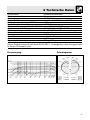
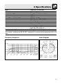
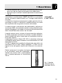
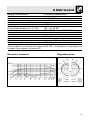
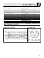
6 Technische Daten
11
Arbeitsweise: Kondensatormikrofon
Richtcharakteristik: Niere
Übertragungsbereich: 20-20.000 Hz
Empfindlichkeit: 6 mV/Pa (-44 dBV bez. auf 1 V/Pa)
Elektrische Impedanz bei 1000 Hz: ≤200 Ω
Empfohlene Lastimpedanz: ≥2000 Ω
Grenzschalldruckpegel für 1% / 3% Klirrfaktor: 139 / 142 dB SPL
Äquivalentschalldruckpegel: 17,5 dB (A) (nach DIN 45412)
Speisespannung: 9 - 52 V Universal-Phantomspeisung
Stromaufnahme: ca. 2 mA
Steckerart: XLR 3-polig
Oberfläche: mattschwarz
Abmessungen: L: 180 mm; ø: 50 mm
Gewicht (netto/brutto): 295 g / 650 g
Dieses Produkt entspricht der Norm EN 50 082-1, vorausgesetzt, dass nachgeschalte-
te Geräte CE-konform sind.
Frequenzgang Polardiagramm
3511_C900M_fsch.qxd 12.07.2006 20:24 Uhr Seite 11

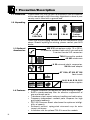
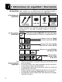
1.1 Precaution
1.2 Unpacking
1.3 Optional
Accessories
1.4 Features
Please make sure that the piece of equipment your microphone
will be connected to fulfills the safety regulations in force in your
country and is fitted with a ground lead.
Check that the packaging contains all of the components listed
above. Should anything be missing, please contact your AKG
dealer.
• Rugged condenser microphone for vocal miking on stage.
• Built-in windscreen/pop filter for effective suppression of
pop and breath noise.
• Transducer shock mount reduces handling and cable noise.
• Frequency-independent cardioid polar response for high
gain before feedback.
• PB 1000 Presence Boost attachment for optimum intelligi-
bility of speech.
• Extremely resilient, spring-steel wire-mesh cap for extra
impact resistance.
• Installation slot for optional TM 40 transmitter module.
1 Precaution/Description
12
1 C 900
M
or
1 PB 1000 1 SA 61 1 micro-
C 900
M
/TM 40
phone bag
• MK 9/10 microphone cable: 10 m (30 ft.)
2-conductor shielded cable with 3-pin male and
3-contact female XLR connectors
• TM 40 transmitter module
• W 880 windscreen
• H 30 universal elastic suspension,
SA 26 stand adapter
• ST 102A, ST 200, ST 305
floor stands
• N 62, N 66, B 18, B 15
phantom power supplies
3511_C900M_fsch.qxd 12.07.2006 20:25 Uhr Seite 12

1.5 C 900
M
,
C 900
M
/TM 40
Fig. 1: Optional
TM 40 transmitter
module.
The AKG C 900
M
is a vocal microphone for professional use on
stage.
A frequency response tailored to vocal reproduction and a car-
dioid polar pattern provide a smooth sound and high gain
before feedback.
A rugged front grill made of spring-steel wire mesh that is
extremely resistant to deformation and a sturdy zinc alloy die-
cast body effectively protect the microphone and transducer
element from damage on stage and on the road.
The outer steel wire mesh grille and a layer of a special fabric
form a very effective windscreen against pop and breath noise
and sibilance.
The supplied PB 1000 Presence Boost attachment provides a
boost of approx. 5 dB between 5 kHz and 9 kHz for optimum
intelligibility of speech.
The C 900
M
features a removable connection module with a 3-
pin XLR connector. You can connect the microphone to both
balanced and unbalanced mixer or amplifier inputs.
You can easily convert the microphone
into a wireless microphone. All you need
to do is remove the XLR connector mod-
ule and replace it with an optional TM 40
transmitter module.
1 Description
13
3511_C900M_fsch.qxd 12.07.2006 20:25 Uhr Seite 13

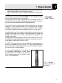
2.1 General
Refer to sections
2.2 and 2.3.
2.2 Input with
Phantom Power
Fig. 2: Connecting
to a balanced input.
Refer to fig. 2.
2.3 Input with No
Phantom Power
Refer to fig. 2.
Important!
2.4 Unbalanced
Input
Fig. 3: Connecting
to an unbalanced
input.
Refer to fig. 3.
The C 900
M
is a condenser microphone and therefore needs a
power supply.
The microphone provides a balanced output on a 3-pin male
XLR connector:
Pin 1: ground
Pin 2: hot
Pin 3: return
You can connect the microphone either to a balanced micro-
phone input with or without phantom power or an unbalanced
microphone input.
1. Use an XLR cable (e.g., the optional MK 9/10 from AKG) to
connect the microphone to a balanced XLR input with
phantom power.
2. Switch the phantom power on. (Refer to the manual of the
unit to which you connected your microphone.)
1. If your mixer provides no phantom power, connect an
optional AKG phantom power supply (N 62 E, N 66 E, B 18,
B 15) between the microphone and the mixer.
Using any power supply other than those recommended
by AKG may damage your microphone and will void the
warranty.
You may connect AKG phantom power supplies to unbalanced
inputs, too.
14
2 Interfacing
2.2
2.3
C 900
M
C 900
M
Phantom
C 900
M
Phantom
3511_C900M_fsch.qxd 12.07.2006 20:25 Uhr Seite 14

Note:
2.5 Optional
TM 40 Transmitter
Module
Start by removing
the XLR connec-
tor module:
Fig. 4: Removing
the XLR connector
module.
Refer to fig. 4.
Install the trans-
mitter module:
Refer to fig. 5.
Fig. 5: Installing the
transmitter module.
Use a cable with a female XLR connector and TS jack plug:
1. On the XLR connector, use a wire bridge to connect pin 1 to
pin 3 and the cable shield.
2. Connect the inside wire of the cable to pin 2 on the XLR
connector and the tip contact of the jack plug.
Unbalanced cables may pick up interference from stray mag-
netic fields near power or lighting cables, electric motors, etc.
like an antenna. This may introduce hum or similar noise when
you use a cable that is longer than 16 feet (5 m).
The optional TM 40 transmitter module allows you to convert
your microphone into a wireless microphone that you can use
with any WMS 40 Series receiver from AKG.
1. Open the fixing screw (1).
2. Pull the XLR connector module (2) out of the microphone
body.
3. To avoid losing the fixing screw (1), screw it into the thread-
ed hole (3) in the XLR connector module.
2 Interfacing
15
1
2
1
2
3511_C900M_fsch.qxd 12.07.2006 20:25 Uhr Seite 15

Refer to fig. 5.
Note:
Replacing the
transmitter
module with the
XLR connector
module:
Fig. 6: Removing
the transmitter
module.
Refer to fig. 6.
Note:
1. Do not forget to check the condition of the battery inside the
transmitter module. If the battery is dead or there is no bat-
tery inside the transmitter module, insert a new battery.
2. Hold the transmitter module (1) to align the contacts (2) with
the microphone.
3. Slide the transmitter module (1) into the microphone body to
the point that the transmitter module (1) will lock with an
audible click.
As the transmitter module locks in place, the electrical con-
nections to the microphone are made automatically.
For details on inserting, replacing, and testing the battery as
well as setting up and operating the transmitter module
refer to the TM 40 transmitter module manual.
1. Insert a ball point pen, small screwdriver, or similar pointed
object into the opening (1) in the microphone body and
press inward.
The transmitter module (2) will unlock and slide out of the
microphone body for about 0.1 inch.
2. Pull the transmitter module (2) out of the microphone.
3. Unscrew the fixing screw (4) from the XLR connector mod-
ule (3).
4. Slide the XLR connector module (3) into the microphone
body to the stop.
5. To fix the XLR connector module (3), screw the fixing screw
(4) down firmly.
Alternatively, you can remove the transmitter module simply by
pulling it out of the microphone body with just enough force to
unlock it. Make sure not to grasp the transmitter module by the
battery compartment. (If you did, you would only open the bat-
tery compartment.)
2 Interfacing
16
4
2
1
3
3511_C900M_fsch.qxd 12.07.2006 20:25 Uhr Seite 16

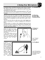
3.1 Introduction
3.2 Working
Distance and
Proximity Effect
3.3 Angle of
Incidence
Fig. 7: Typical
microphone
position.
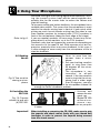
3.4 Feedback
Fig. 8: Microphone
placement for maxi-
mum gain before
feedback.
A handheld vocal microphone provides many ways of shaping
the sound of your voice as it is heard over the sound system.
The following sections contain useful hints on how to use your
microphone for best results.
The following sections apply to both the hardwire C 900
M
and
the wireless version with an optional TM 40 transmitter module
installed.
Basically, your voice will sound the bigger and mellower, the
closer you hold the microphone to your lips. Moving away from
the microphone will produce a more reverberant, more distant
sound as the microphone will pick more of the room’s rever-
beration.
You can use this effect to make your voice sound aggressive,
neutral, insinuating, etc. simply by changing your working dis-
tance.
Proximity effect is a more or less dramatic boost of low fre-
quencies that occurs when you sing into the microphone from
less than 2 inches. It gives more "body" to your voice and an
intimate, bass-heavy sound.
Sing to one side of the micro-
phone or above and across
the microphone’s top. This
provides a well-balanced, nat-
ural sound.
If you sing directly into the
microphone, it will not only
pick up excessive breath
noise but also overemphasize
"sss", "sh", "tch", "p", and "t"
sounds.
Feedback is the
result of part of
the sound project-
ed by a speaker
being picked up
by a microphone,
fed to the amplifi-
er, and projected
again by the
speaker. Above a
specific volume or
"system gain"
setting called
the feedback
17
3 Using Your Microphone
3511_C900M_fsch.qxd 12.07.2006 20:25 Uhr Seite 17

Refer to fig. 8.
3.5 Backing
Vocals
Fig. 9: Two vocalists
sharing a micro-
phone.
3.6 Installing the
PB 1000
Fig. 10: Capsule
without (a) and with
(b) PB 1000.
Important!
threshold, the signal starts being regenerated indefinitely, mak-
ing the sound system howl and the sound engineer des-
perately dive for the master fader to reduce the volume and
stop the howling.
To increase usable gain before feedback, the microphone has a
cardioid polar pattern. This means that the microphone is most
sensitive to sounds arriving from in front of it (your voice) while
picking up much less of sounds arriving from the sides or rear
(from monitor speakers for instance).main ("FOH") speakers in
front of the microphones (along the front edge of the stage).
If you use monitor speakers, be sure never to point any micro-
phone directly at the monitors, or at the FOH speakers.
Feedback may also be triggered by resonances depending on
the acoustics of the room or hall. With resonances at low fre-
quencies, proximity effect may cause feedback. In this case, it
is often enough to move away from the microphone a little to
stop the feedback.
1. Never let more than two
persons share a micro-
phone.
2. Ask your backing vocalists
never to sing more than
35 degrees off the micro-
phone axis.
The microphone is very
insensitive to off-axis
sounds. If the two vocalists
were to sing into the micro-
phone from a wider angle
than 35 degrees, you may
end up bringing up the fader of the microphone channel far
enough to create a feedback problem.
1. Unscrew and
remove the wire
mesh cap.
2. Slip the PB 1000
on the micro-
phone cap-
sule to the stop, slightly turning the attachment as you push
it home.
When installing or removing the PB 1000, make sure to grip
the capsule and shock mount firmly with your thumb and
forefinger in order to prevent the capsule being severed
from the shock mount.
3 Using Your Microphone
18
a
b
3511_C900M_fsch.qxd 12.07.2006 20:25 Uhr Seite 18

4.1 Microphone
Body
4.2 Internal
Windscreen
To clean the surface of the microphone body, use a soft cloth
moistened with water.
1. Unscrew the front grill from the microphone CCW.
2. Remove the windscreen from the from grill and wash the
windscreen in soap suds.
3. Allow the windscreen to dry overnight.
4. Replace the windscreen in the front grill and screw the front
grill on the microphone CW.
19
4 Cleaning
3511_C900M_fsch.qxd 12.07.2006 20:25 Uhr Seite 19

20
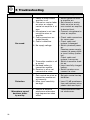
5 Troubleshooting
No sound.
Distortion.
Microphone sound
becomes duller
by and by.
1. Power to mixer and/or
amplifier is off.
2. Channel or master fader
on mixer, or volume
control on amplifier is at
zero.
3. Microphone is not con-
nected to mixer or
amplifier.
4. Cable connectors are
seated loosely.
5. Cable is defective.
6. No supply voltage.
7. Transmitter module is off
or muted.
8. No/dead battery in
transmitter module.
9. Receiver is off or not
connected to mixer.
1. Gain control on mixer or
transmitter module not
set correctly.
2. Mixer input sensitivity
too high.
• Internal or external
windscreen attenuates
high frequencies when
soiled.
1. Switch power to mixer
or amplifier on.
2. Set channel or master
fader on mixer or vol-
ume control on amplifier
to desired level.
3. Connect microphone to
mixer or amplifier.
4. Check cable connectors
for secure seat.
5. Check cable and
replace if damaged.
6. Switch phantom power
on.
Phantom power supply:
connect to power outlet
or insert battery (batter-
ies).
Check cable and
replace if necessary.
7. Switch transmitter mod-
ule on.
8. Insert new/fully charged
battery.
9. Switch receiver on or
connect to mixer.
1. Set gain control to stop
distortion.
2. Insert 10 dB preattenua-
tion pad between micro-
phone cable and input.
• Clean internal or exter-
nal windscreen.
Problem
Possible Cause Remedy
3511_C900M_fsch.qxd 12.07.2006 20:25 Uhr Seite 20
Seite wird geladen ...
Seite wird geladen ...
Seite wird geladen ...
Seite wird geladen ...
Seite wird geladen ...
Seite wird geladen ...
Seite wird geladen ...
Seite wird geladen ...
Seite wird geladen ...
Seite wird geladen ...
Seite wird geladen ...
Seite wird geladen ...
Seite wird geladen ...
Seite wird geladen ...
Seite wird geladen ...
Seite wird geladen ...
Seite wird geladen ...
Seite wird geladen ...
Seite wird geladen ...
Seite wird geladen ...
Seite wird geladen ...
Seite wird geladen ...
Seite wird geladen ...
Seite wird geladen ...
Seite wird geladen ...
Seite wird geladen ...
Seite wird geladen ...
Seite wird geladen ...
Seite wird geladen ...
Seite wird geladen ...
Seite wird geladen ...
Seite wird geladen ...
Seite wird geladen ...
Seite wird geladen ...
Seite wird geladen ...
Seite wird geladen ...
Seite wird geladen ...
Seite wird geladen ...
Seite wird geladen ...
Seite wird geladen ...
Seite wird geladen ...
Seite wird geladen ...
Seite wird geladen ...
Seite wird geladen ...
-
 1
1
-
 2
2
-
 3
3
-
 4
4
-
 5
5
-
 6
6
-
 7
7
-
 8
8
-
 9
9
-
 10
10
-
 11
11
-
 12
12
-
 13
13
-
 14
14
-
 15
15
-
 16
16
-
 17
17
-
 18
18
-
 19
19
-
 20
20
-
 21
21
-
 22
22
-
 23
23
-
 24
24
-
 25
25
-
 26
26
-
 27
27
-
 28
28
-
 29
29
-
 30
30
-
 31
31
-
 32
32
-
 33
33
-
 34
34
-
 35
35
-
 36
36
-
 37
37
-
 38
38
-
 39
39
-
 40
40
-
 41
41
-
 42
42
-
 43
43
-
 44
44
-
 45
45
-
 46
46
-
 47
47
-
 48
48
-
 49
49
-
 50
50
-
 51
51
-
 52
52
-
 53
53
-
 54
54
-
 55
55
-
 56
56
-
 57
57
-
 58
58
-
 59
59
-
 60
60
-
 61
61
-
 62
62
-
 63
63
-
 64
64


AKG C 900-TM 40 Bedienungsanleitung
- Kategorie
- Mikrofone
- Typ
- Bedienungsanleitung
- Dieses Handbuch eignet sich auch für
in anderen Sprachen
- français: AKG C 900-TM 40 Le manuel du propriétaire
- español: AKG C 900-TM 40 El manual del propietario
- italiano: AKG C 900-TM 40 Manuale del proprietario
- português: AKG C 900-TM 40 Manual do proprietário
Verwandte Artikel
-
AKG C 5900 Bedienungsanleitung
-
-
-
-
-
-
-
-
-