AER compact XL Bedienungsanleitung
- Kategorie
- Musikausrüstung
- Typ
- Bedienungsanleitung

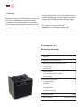
Compact XL
Bedienungsanleitung, User Manual 02/2022

2
Compact XL
Bedienungsanleitung
Inhalt Seite
1. Einleitung 2
2. Wichtige Sicherheitshinweise 3
3. Bedienungselemente und Anschlüsse 4
3.1 Frontseite 4
3.2 Rückseite 5
4. Inbetriebnahme 6
4.1 Anschließen und Einschalten 6
4.2 Aussteuern 6
5. Funktionsbeschreibung 6
5.1 Klangregelung 6
5.2 Eekte 7
5.3 Couple in 7
5.4 Fuß-Schalter 7
5.5 Phantomspeisung 8
6. Technische Daten 14/15
7. Blockschaltbild www.aer-music.de
1. Einleitung
Willkommen bei der AER. Wir freuen uns, dass Sie
sich für den Compact XLentschieden haben.
Sie haben ür einen professionellen, kompakten
und leistungsstarken Akustik-Verstärker gewählt.
Alle AER-Verstärkersysteme sind dynamikkontrol-
liert, das bedeutet für Sie Zuverlässigkeit und un-
verzerrte Wiedergabe auch bei hoher Lautstärke,
und das bei verblüend kleinen Abmessungen
und geringem Gewicht.
Wir würden uns freuen, wenn der
CompactXL ein wichtiges Werkzeug für
Sie wird und wünschen Ihnen viel Spaß damit.

3
2. Wichtige Sicherheitshinweise
Die folgenden Hinweise dienen der Minimierung des Verletzungsrisikos durch Feuer und Stromschlag.
1. Lesen Sie diese Sicherheitshinweise aufmerksam,
bevor Sie das Gerät benutzen.
2. Bewahren Sie diese Sicherheitshinweise sorgfältig auf.
3. Beachten Sie alle Warnungen, Anweisungen und
zusätzliche Aufschriften auf dem Gerät.
4. Dieses Gerät wurde nur für den Betrieb unter
normalen klimatischen Bedingungen (gemäßigtes
Klima) entwickelt.
5. Installieren und verwenden Sie Ihren Verstärker
nicht in der Nähe von Wasser, oder wenn Sie selbst
naß sind.
6. Setzen Sie Ihr Gerät keinen plötzlichen großen
Temperaturschwankungen aus. Dies könnte
Kondenswasserbildung im Gerät hervorrufen und
es beschädigen. Im Fall von Kondenswasserbildung
lassen sie bitte das Gerät vor der Benutzung voll-
kommen austrocknen.
7. Betreiben Sie Ihr Gerät an einem geschützten Ort,
wo niemand auf Kabel treten oder über sie stolpern
und sie beschädigen kann.
8. Achten Sie auf eine ungehinderte Belüftung des
Verstärkers, verdecken Sie nie Belüftungsönungen
oder -gitter.
9. Ziehen Sie immer den Netzstecker, wenn Sie den
Verstärker reinigen oder für längere Zeit nicht
benutzen. Verwenden Sie für die Reinigung ein tro-
ckenes Tuch. Vermeiden Sie den Einsatz von Putz-
mitteln und achten Sie darauf, daß keine Flüssigkeit
in das Gerät eindringt.
10. Verwenden Sie nur passende Ersatzsicherungen
mit gleichem Nennstrom und gleicher Abschaltcha-
rakteristik. Sicherungen niemals icken! Ziehen Sie
vor dem Ersetzen einer Sicherung den Netzstecker.
Brennt eine Sicherung nach kurzer Zeit erneut
durch, muß das Gerät überprüft werden.
11. Installieren Sie Ihren Verstärker nie in der Nähe von
Geräten mit starken elektromagnetischen Feldern,
wie großen Netztransformatoren, rotierenden
Maschinen, Neonbeleuchtung etc. Verlegen Sie
Signalkabel nicht parallel zu Netzkabeln.
12. Das Innere des Geräts enthält keine durch den
Benutzer zu wartenden Teile. Um eine Gefährdung
durch Stromschlag auszuschließen, darf das Gerät
nicht geönet werden. Überlassen Sie Wartung,
Abgleich und Reparatur qualifziertem Fachpersonal.
Im Fall eines Fremdeingris erlischt die 2-jährige
Garantie.
13. Für die Einhaltung der EMV-Forderung müssen
geschirmte Kabel mit korrekt angeschlossenen
Steckverbindern für alle Signalanschlüsse verwen-
det werden.
14. Verwenden Sie immer einen geerdeten Netzan-
schluß mit der richtigen Netzspannung. Falls Sie
Zweifel haben, ob der Anschluß geerdet ist, lassen
Sie ihn durch einen qualifzierten Fachmann über-
prüfen.
15. Verkabeln Sie Ihren Verstärker nur im ausgeschalte-
ten Zustand.
16. Dieses Gerät muß in der Nähe einer Netzsteck-
dose eingesetzt werden und sich leicht vom Netz
trennen lassen. Der Netzstecker muß ohne weiteres
zugänglich sein. Achten Sie darauf, daß niemand
auf das Netzkabel tritt und daß es nicht einge-
klemmt werden kann, insbesondere an Steckern,
Kabelkupplungen und an der Stelle, wo es aus dem
Gerät austritt.
17. Dieses Produkt kann bleibende Hörschäden ver-
ursachen. Betreiben Sie es nicht für längere Zeit
mit hoher oder unangenehmer Lautstärke. Falls Sie
einen Hörverlust oder Klingeln in den Ohren be-
merken, sollten Sie einen Ohrenarzt aufsuchen.
18. Stellen Sie das Produkt nicht in der Nähe von
Wärmequellen wie Heizkörpern oder anderen
Gegenständen, die Wärme abgeben, auf.
19. Stellen Sie keine Quellen von oenem Feuer, wie
Kerzen, auf das Gerät.
20. Achten Sie darauf, daß keine Gegenstände auf das
Gerät fallen und keine Flüssigkeiten durch Önun-
gen in das Gehäuse gelangen. Stellen Sie sicher,
daß keine üssigkeitsgefüllten Gegenstände, wie
Vasen, auf das Gerät gestellt werden.
21. Stellen Sie dieses Gerät nicht auf einen
unstabilen Rollwagen, Ständer, Stativ,
Ausleger oder Tisch. Das Gerät kann
herunterfallen und ernsthafte Verletzun-
gen verursachen oder selbst beschädigt
werden.
CAUTION
RISK OF ELECTRIC SHOCK
DO NOT OPEN
ATTENTION
RISQUE DE CHOC ELECTRIQUE
NE PAS OUVRIR
Das Blitzsymbol im
gleichseitigen Dreieck
soll den Benutzer vor un-
isolierter, gefährlicher Spannung
innerhalb des Gehäuses dieses
Produkts warnen, die zu einem
elektrischen Schlag führen kann.
Das Ausrufezeichen im
gleichseitigen Dreieck
soll den Benutzer auf
wichtige Hinweise zu Betrieb und
Instandhaltung (Service) dieses
Produkts in den beiliegenden
schriftlichen Unterlagen aufmerk-
sam machen.

4
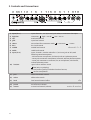
3. Bedienelemente und Anschlüsse
channels 1 + 2
efx
mains & master
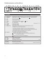
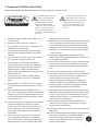
3.1 Frontseite
1) input (ch. 1) Eingang Kanal 1, Klinkenbuchse 6,35 mm, Instrumenten- oder Line-Eingang
2) high/low Abschwächer, high = Abschwächer aus, low = Abschwächer an
3) clip Übersteuerungsanzeige
4) gain Eingangspegel-Regler
5) colour Schalter Klangfarbenlter = aus , = ein
6) bass Basspegel-Regler
7) middle Mittenpegel-Regler
8) treble Höhenpegel-Regler
9) input (ch. 2) Eingang, Kanal 2, Kombibuchse für XLR oder Klinke (6,35 mm)
mit folgenden Anschlußmöglichkeiten:
• XLR-Stecker: Mikrofon, symmetrisch, mit 48 V Phantomspeisung
• Stereo-Klinkenstecker: Mikrofon, symmetrisch, ohne Phantomspeisung
• Mono-Klinkenstecker: Instrument, Line oder Mikrofon,
unsymmetrisch, ohne Phantomspeisung
10) line/mic Signalquellen-Wahlschalter der Kombibuchse:
= line (nur über Klinkenstecker) für Instrumente (Tonabnehmer)
und andere line-Quellen,
= mic (nur über XLR-Stecker) für Mikrofone
11) pan Eektverteilungs-Regler
12) select Eektauswahlschalter
13) level Pegel-Regler interner Eekt
14) power Betriebszustandsanzeige
15) master Gesamtpegel-Regler (Lautstärke)
CXL_IF_120731
12344
56 6
78910 3811 12 13 14 15

5
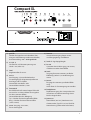
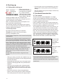
3.2 Rear side
1) gnd lift
Schalter für Signalmasse-Schutzleiter Tren-
nung zur Verhinderung von Brummschleifen,
Grundeinstellung: aus = nicht gedrückt.
2) 9 V (ch. 1)
Schaltet die 9-V-Phantomspeisung von
Kanal 1 ein (siehe 5.4).
3) level
Pegeleinsteller für aux in
4) aux in
Aux-Eingang, 3,5-mm-Klinkenbuchse.
Zusatzeingang für allgemeine Quellen mit
Line-Pegel, z.B. CD-Spieler
Verwendbar mit Mono- oder
Stereo-Klinkenstecker 3,5 mm
5) footswitch
Anschlußbuchse für einen Doppel-Fußschal
ter zum Ein- und Ausschalten des eingebau
ten bzw. externen Eekts.
Stereo-Klinkenbuchse, Belegung:
Tip = Schalter für den eingebauten Eekt
Ring = Schalter für den externen Eekt
(send / return)
6) tuner: Ausgang, vor master,
für ein Stimmgerät
7) line out
Vorverstärkerausgang hinter master
und Klangregelung, mit Eekten
8) level: DI-Signalpegel-Regler
9) DI-out
Symmetrischer XLR-Ausgang, vor master,
schaltbar mit oder ohne Eekte
10) send
Ausgang für einen externen, parallelen
Eektweg (siehe 5.2) in Verbindung mit
return
11) return
Eingang des externen, parallelen Eekt-
wegs.
Auch allein als Zusatzeingang verwendbar.
12) headphones
Kopfhörerausgang. Der Lautsprecher des
Verstärkers wird bei Verwendung dieser
Buchse abgeschaltet.
13) power on
Netzschalter (ein/aus), kombiniert mit
Gerätestecker (Typ IEC C14) und Fach für
Netzsicherung (siehe technische Daten).
footswitch
Compact XL
gnd
lift
9 V
tip = int. e.
ring = ext. e.
phantom
power
level aux in
L
R
tuner line out
The Acoustic People
level DI-out send return headphones
CXL_IB_120731
footswitch
Compact XL
gnd
lift
9 V
tip = int. e.
ring = ext. e.
phantom
power
level aux in
L
R
tuner line out
The Acoustic People
level DI-out send return headphones
CXL_IB_120731
12345678910 11 12
13

6
4.2 Aussteuern
Durch richtiges Aussteuern passen Sie den
Compact XL an Ihre Signalquellen (Gitarren-Tonab-
nehmer, Mikrofone, usw.) an.
Lassen Sie dazu den master-Regler zunächst auf
Linksanschlag stehen
Bringen Sie den line/mic-Schalter (channel 2) in
Stellung mic, wenn Sie ein Mikrofon verwenden.
Stellung line eignet sich für Gitarrentonabnehmer
aller Art und die meisten anderen Signalquellen.
Erhöhen Sie nun schrittweise die betre ende
gain-Einstellung gerade so weit, daß die rote
clip-Anzeige auch bei lautstarkem Spiel noch nicht
au euchtet. Dadurch behalten Sie noch etwas
Spielraum für unerwartete Lautstärkespitzen.
Sehr starke Quellen können trotz niedriger gain-
Einstellung eine clip-Anzeige hervorrufen. Solche
Quellen können Sie zunächst durch Drücken des
high/low-Schalters (channel 1) abschwächen.
Stellen Sie zum Schluß mit dem master-Regler die
gewünschte Lautstärke ein.
• Wenn die gain-Einstellung zu niedrig ist, erreicht
der Verstärker nicht die gewünschte Lautstärke,
oder es macht sich störendes Rauschen bemerk-
bar.
• Bei zu hoher Einstellung treten hörbare Verzerrun-
gen (clipping) auf. Durch die clip-Leuchte werden
Sie davor rechtzeitig gewarnt.
4. Inbetriebnahme
4.1 Anschließen und Einschalten
Prüfen Sie, ob die Netz-
spannung vor Ort
(z.B. 230 V in Europa,
120 V in den USA) mit
der zulässigen Netz-
spannung des Gerätes
übereinstimmt. Die entsprechenden Hinweise
und Sicherheitssymbole sind auf der Rückseite
des Gerätes angegeben. Stellen Sie danach alle
gewünschten Kabelverbindungen her und schalten
Sie das Gerät ein. Die grüne power-Kontrollleuchte
signalisiert Betriebsbereitschaft.
• Wenn das Instrument einen Lautstärke-Regler
besitzt, stellen Sie diesen zum Aussteuern anfangs
auf höchste Lautstärke. Nehmen Sie ihn aber zu-
rück, falls die clip-Anzeige schon früh aueuchtet
und das Aussteuern schwierig ist.
• Stellen Sie immer sicher, daß Sie volle Batterien in
Ihrem (aktiven) Pickup-System verwenden. Brum-
men und Verzerrungen können auch die Folge
einer leeren Batterie sein.
• Wenn mehrere Eingänge gleichzeitig in Gebrauch
sind, legen Sie durch die einzelnen gain-Einstel-
lungen auch das Mischungsverhältnis fest.
• Die gain-Regler von unbenutzten Eingängen
sollten auf Linksanschlag bleiben.
5. Funktionsbeschreibung
5.1 Klangregelung
Die Klangregelung des Compact XL ist eine hoch-
wertige Klangbeein ussung, die den natürlichen
Ton von Instrumenten und Stimme erhält und Ihnen
die Möglichkeit zur gezielten Akzentuierung bietet.
In Mittelstellung von bass, middle und treble und
bei nicht gedrückten colour-Schalter verhält sich die
Klangregelung neutral und beeinußt den Klang
nicht.
Bereits in Neutralstellung erzeugt der Verstärker ein
sehr angenehmes, natürliches Klangbild, das Sie
mit dem colour-Filter grundsätzlich färben können.
Dabei werden die Mitten abgesenkt und die Höhen
angehoben. Der Ton wird oener und leichter
und eignet sich besonders für Zupftechniken. Die
Klangregelung kann die Wirkung des colour-Filters
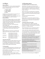
unterstützen oder mildern (siehe Abb. unten)
colour bass middle treble
colour bass middle treble
A: mit colour-Filter
(Schalter gedrückt)
treble reduzieren um
evtl. Schärfe abzu-
mildern
B: ohne colour-Fil-
ter (Schalter nicht
gedrückt)
treble anheben um
den Ton zu önen
Hinweis: Die Klangregelung wirkt sich auch auf die Aus-
steuerung aus. Falls die clip-Anzeige öfter aueuchtet,
verringern Sie mit dem gain-Regler die Aussteuerung
etwas (siehe auch 4.2).

7
5.4 Phantomspeisung
48-V-Phantomspeisung am Mikrofoneingang
Mikrofone, die eine 48-V-Phantomspeisung (P 48)
erfordern, können über einen XLR-Stecker direkt an
input 2 angeschlossen werden.
Die 48-V-Phantomspeisung ist im Auslieferungszu-
stand aktiviert, kann aber durch eine interne Steck-
brücke deaktiviert werden (siehe Hinweis).
Bei Anschluß über Klinkenstecker ist die 48-V Phan-
tomspeisung nicht wirksam. Verwenden Sie den
Klinkenanschluß für Mikrofone, die nicht an Phantom-
speisung angeschlossen werden dürfen.
Lesen Sie dazu bitte auch die allgemeinen Hinweise
zur Phantomspeisung.
Bitte beachten Sie: Für den oben genannten Ein-
gri muß das Gerät geönet werden, deshalb darf
die De-/Aktivierung der Phantomspeisung nur in
einer Fachwerkstatt durchgeführt werden.
9-V-Phantomspeisung am Line-Eingang
Mit der 9-V-Phantomspeisung können entsprechend
vorbereitete Instrumenten-Vorverstärker mit Strom
versorgt werden (anstelle einer Batterie). Solche Vor-
verstärker werden über ein Stereo-Klinkenkabel an
input 1 angeschlossen.
Signalquellen, die keine Phantomspeisung benötigen,
sollten vorsichtshalber immer über ein Mono-Klinken-
kabel (nicht stereo) angeschlossen werden. Dadurch
wird ausgeschlossen, daß die Phantomspannung zur
Signalquelle gelangt und diese möglicherweise be-
schädigt. Achten Sie auch darauf, daß die Klinkenste-
cker voll (bis zum Anschlag) eingesteckt sind.
Hinweis zur Benutzung der Phantomspeisung
Phantomspeisung bedeutet Stromversorgung
eines Audiogeräts (z.B. Mikrofon) über die Audio-
kabelverbindung.
Schließen Sie an einen Eingang mit (eingeschal-
te-ter) Phantomspeisung nur Geräte an, die dafür
geeignet sind!
Diese Geräte sind entsprechend gekennzeichnet,
achten Sie dabei auch auf die zulässige Stromauf-
nahme (siehe tech. Daten).
Manche Geräte benötigen zwar keine Phantomspei-
sung, können aber damit 'leben'.
Bei anderen Geräten, die nicht ausdrücklich für den
Betrieb mit Phantomspeisung entwickelt wurden,
können erhebliche Störungen und auch Schäden
auftreten.
Bei Unsicherheit erkundigen Sie sich bitte beim
Hersteller des von Ihnen verwendeten Geräts!
5.2 Eekte
Der Compact XL verfügt über einen eingebauten
(internen) digitalen Eektprozessor. Mit dem select-
Schalter können Sie zwischen 4 unterschiedlichen
Eekten wählen:
1 = reverb 1 (short)
2 = reverb 2 (long)
3 = delay (320 ms)
4 = chorus
Der eects-level-Regler bestimmt die Intensität des
Eekts (Linksanschlag = kein Eekt).
Zusätzlich wird der Eekt durch den eects-pan-Reg-
ler einem oder beiden Kanälen zugeteilt (siehe unten).
Externe Eekte
Darüber hinaus kann ein zusätzliches Eektgerät
(externer Eekt) an den Verstärker angeschlossen
werden. Benutzen Sie dazu bitte die auf der Rückseite
bendlichen Buchsen send und return (send geht zum
Eingang, return kommt vom Ausgang des externen
Geräts). Die Intensität des externen Eekts wird durch
das externe Eektgerät bestimmt. Der externe Eekt-
weg arbeitet parallel. Parallel bedeutet, daß der Eekt-
anteil (z.B. Hall) dem Originalsignal beigemischt wird.
pan
Mit dem eects-pan-Regler können Sie beide Eekte
stufenlos den Verstärkerkanälen zumischen:
Linksanschlag: interner Eekt auf channel 1
externer Eekt auf channel 2
Mittelstellung: interner Eekt auf channel 1 + 2
externer Eekt auf channel 1 + 2
Rechtsanschlag: interner Eekt auf channel 2
externer Eekt auf channel 1
Verzerrungen im Eekt vermeiden
Eine Übersteuerung der internen oder externen
Eekteinheit wird möglicherweise nicht durch
die clip-Kontrolleuchte angezeigt. Wenn hörbare Ver-
zerrungen im Eekt auftreten, nehmen Sie die gain-
Regler zurück, bis die Verzerrungen beseitigt sind. Die
vorherige Lautstärke können Sie anschliessend mit
dem master-Regler wiederherstellen.
5.3 Footswitch
An die footswitch-Buchse auf der Rückseite des Gerä-
tes kann mit einem Stereokabel ein Standard-Doppel-
fußschalter (An-/Aus-Schalter) angeschlossen werden.
Mit diesem werden der interne und der externe Eekt
ein/aus geschaltet. Als Fußschalter eignen sich Aus-
führungen, die durch einmaliges Treten eingeschaltet
und durch nochmaliges Treten wieder ausgeschaltet
werden.
Wir wünschen Ihnen viel Spaß mit Ihrem Compact XL!

8
Compact XL
User Manual
Contents Page
1. Introduction 8
2. Important Safety Instructions 9
3. Controls and connections 10
3.1 Front side 10
3.2 Rear side 11
4. Starting up 12
4.1 Cabling and switching-on 12
4.2 Level adjustment 12
5. Functional characteristics 12
5.1 Tone control 12
5.2 Eects 13
5.3 Footswitch 13
5.4 Phantom powering 13
6. Technical specications 14/15
7. Circuit diagram www.aer-music.de
1. Introduction
Welcome to AER.
Thank you for choosing the Compact XL.
The Compact XL is a professional, compact and po-
werful amplier system. Especially developed for the
enhancement of acoustic instruments it is nonethe-
less suitable for other instruments, even electrical
ones.
Two independend channels provides you to connect
two instruments (f. eg. microphone and stringed inst-
rument) at the same time and even a playpack signal.
Performance-optimized power amplier with large
reserves. Equipped with a 2-way speaker system, it
achieves distortion-free playback at high volume and
sucient dynamics without loss of sound.
The Compact XL is like all AER-systems subtly
dynamically controlled, which ensures absolute relia-
bility in full load operation despite strikingly
small sizes and little weight.
Read on and have fun using your Compact XL!

9
2. Important Safety Instructions
The following guidelines shall help minimize the risk of injury through re or electric shock.
1. Carefully read these safety notes before you
use the device!
2. Keep these safety notes in a safe place.
3. Pay attention to all warnings, instructions and
additional texts on the unit.
4. This device was only designed for operation
under normal climatic conditions (temperate
climate).
5. Do not install or use your amp in close proximi-
ty to water or if you are wet yourself.
6. Do not subject your device to sudden and
severe temperature changes. This could cause
moisture condensation inside the unit, which
could damage it. In the event of moisture
condensation allow the device to dry out com-
pletely before use.
7. Use your amp in a safe place where nobody
can step on cables or trip over and damage
them.
8. Pay attention to an unhindered air circulation
around the amp, never obstruct the air vents or
grilles.
9. Always pull the mains plug before cleaning
your amp or when left unused for a long period
of time. Use only a dry cloth for cleaning. Avoid
the use of detergents and do not let any liquids
seep into the unit.
10. Use only the right fuses with the same current
rating and trigger characteristic as replace-
ments. Never mend fuses! Pull the mains plug
before replacing a fuse. Should a fuse blow
again after a short while, the device needs to
be checked.
11. Never install your amp close to devices with
strong electromagnetic elds such as large
mains transformers, revolving machines, neon
illumination etc. Do not lay signal cables paral-
lel to power current cables.
12. There are no user-serviceable components inside the
unit. To avoid the risk of an electric shock, the unit
must not be opened. All maintenance, adjustment
and repair works should be carried out by qualied
sta only. Any unauthorized tampering will void the
2-year warranty.
13. In keeping with the EMV regulations screened
cables with correctly tted connectors must be used
for all signal connections.
14. Always use an earthed power supply with the correct
mains voltage. If you are in doubt about the power
outlet ground, have it checked by a qualied techni-
cian.
15. Cable up your amp only when it is powered o.
16. This device should be installed near the socket outlet
and disconnection of the device should be easily
accessible. The mains plug of the power
supply shall remain readily operable. Protect the
power cord from being walked on or pinched par-
ticularly at plugs, convenience receptacles and the
point where they exit from the apparatus.
17. This product may cause permanent hearing loss. Do
not operate for long periods of time at a high volume
level or at any level that is uncomfortable. If you ex-
perience any hearing loss or ringing in the ears, you
should consult an audiologist.
18. The product should be located away from heat
sources such as radiators, heat registers or other
products that produce heat.
19. Do not place any open sources of re, like candles, on
the device.
20. Care should be taken so that objects do not fall onto
the device and liquids are not spilled into the
enclosure through openings. Ensure that no
objects lled with liquids, such as vases, are
placed on the device.
CAUTION
RISK OF ELECTRIC SHOCK
DO NOT OPEN
ATTENTION
RISQUE DE CHOC ELECTRIQUE
NE PAS OUVRIR
The lightning ash with the
arrow head symbol within
an equilateral triangle is
intended to alert the user to
the presence of unisolated
‚dangerous voltage‘ within this
product´s enclosure that may
be of sucient magnitude to
constitute a risk of electric shock
to persons.
The exclamation point within an
equilateral triangle is intended
to alert the user to the presence
of important operating and main-
tenance (servicing) instructions in
the literature accompanying this
product.

10
3. Controls and Connections
channels 1 + 2
efx
mains & master
1) input (ch. 1) input channel 1, 1/4“ (6,35 mm) jack socket, instrument or line input
2) high/low attenuator, high = att. o, low = att. on
3) clip overload indicator
4) gain input level control
5) colour tone colour lter activation switch = not active , = active
6) bass bass level control
7) middle middle level control
8) treble treble level control
9) input (ch. 2) Input, channel 2, combo socket for ¼“ (6.35 mm) jack or XLR, with
following connection options:
• XLR connector: microphone, balanced, with 48 V phantom power
• stereo jack connector: microphone, balanced, without phantom power
• mono jack connector: instrument, line, or microphone, unbalanced,
without phantom power.
10) line/mic signal source selector switch:
line (only via jackplug)
for instruments (pickup) and other line level sources,
mic for microphones.
11) pan eect distribution control
12) select eect select switch
13) level level control internal eect
14) power on/o status indicator
15) master master level control (volume)
CXL_IF_120731
12344
56 6
78910 3811 12 13 14 15
3.1 Front side

11
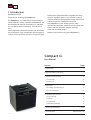
3.2 Rear side
1) gnd lift
Disconnects signal ground from protective
ground, thereby eliminating hum problems
with so-called ground loops. This button
should normally remain switched o.
2) 9 V (ch. 1)
Switches on the 9 V phantom power for
channel 1 (see 5.4)
3) aux evel
Level control for aux in
4) aux in
Auxiliary input, 3.5 mm jack socket.
Additional input for general sources
with line level, e.g. CD player
Mono or stereo jack plugs can be used.
5) footswitch
Connector for a dual footswitch switching the
internal and external eect on/o.
Stereo jack socket, assignment:
Tip = switch for internal eect
Ring = switch for external eect (send /
return)
6) tuner
Output, pre master, for a tuner.
7) line out
Preamplier output post master and tone
controls, with eects
8) level
DI-signal-level
9) DI-out
Balanced XLR output, pre master, switchable
with or without eects.
10) send
Output for external, parallel eect loop (see
5.2) in conjunction with return
11) return
Input of the external, parallel eect path
Can also be used alone as an additional
input.
12) headphones
Output for headphones. The loudspeaker
of the amplier is switched o when this
socket is used.
13) power on
Power on/o switch, combined with mains
inlet (IEC C14 type) and compartment for
mains fuse (see technical data).
footswitch
Compact XL
gnd
lift
9 V
tip = int. e.
ring = ext. e.
phantom
power
level aux in
L
R
tuner line out
The Acoustic People
level DI-out send return headphones
CXL_IB_120731
footswitch
Compact XL
gnd
lift
9 V
tip = int. e.
ring = ext. e.
phantom
power
level aux in
L
R
tuner line out
The Acoustic People
level DI-out send return headphones
CXL_IB_120731
12345678910 11 12
13

12
4. Starting up
4.1 Cabling and switching on
Before connecting to
mains, please ensure that
your local mains voltage
(e.g. 120V in the USA,
230V in Europe) matches
the voltage rating of the
device, which is printed
on the type label on the rear side of the unit.
Connecting to the wrong mains voltage may cause
serious damage to your amplier!
Make sure the phantom power (see chapter 5.4) is
not switched on unintentionally.
Then connect all cables according to your applica-
tion and switch the device on. The green power LED
indicates operational readiness.
4.2 Level adjustment
By proper level adjustment you adapt the
Compact XSL to your signal sources (guitar
pick-ups, microphones, etc.).
For this purpose keep the master control initially fully
anticlockwise.
Set the line/mic switch (channel 2) to position mic if
you are using a microphone. Position line is suitable
for all types of guitar pickups and most other sources.
Now gradually increase the appropriate gain setting
as far as possible but without triggering the red clip
indicator, even when you play loud. Thereby you keep
some headroom for unexpected peak levels.
Very strong sources may cause a clipping warning
despite a low gain setting. Such sources can be
attenuated rst by pushing the high/low switch
(channel 1).
Finally set the desired volume using the master
control.
• If the gain setting is too low, the amplier may not
reach the desired volume, or distracting noise may
become noticeable.
• Setting the gain too high causes distorted sound
(clipping). The clip light will warn you before this
happens.
• If you use an instrument with a volume control,
start o with full volume but reduce it if the clip
indicator lights up early and the level adjustment
is dicult.
• Please ensure there is always enough battery
power in your (active) pick-up system. Humming
and sizzling may be caused by an empty battery.
• If several inputs are used simultaneously, you also
determine the mixing ratio by the individual gain
settings.
• The gain controls of any unused inputs should stay
fully anticlockwise.
5. Functional characteristics
5.1 Tone control
The tone controls of the Compact XL are a high-
quality sound modication tool that preserves the
natural tone of instruments and voice and allows you
to apply targeted accentuations.
If bass, middle, and treble are in center position and
the colour switch is not pushed, the tone controls are
neutral and have no inuence on the sound.
The amplier will already provide a very pleasant, na-
tural sound when all controls are in neutral position,
which you can then principally alter with the colour
lter: This will reduce the midrange and bring out the
trebles. The sound becomes more open and lighter
and is particularly suitable for nger picking techni-
ques. The tone controls can support or attenuate the
eect of the colour lter (see illustration below).
Please note: The tone controls have an eect on the
signal level. If the clip indicator ashes more fre-
quently, reduce the level a bit using the gain control
(see also 4.2)
colour bass middle treble
colour bass middle treble
With colour-lter
(switch pressed)
reduce treble
to soften possible
harshness.
Without colour-lter
(switch not
pressed)
boost treble
to brighten the
sound.

13
5.2 Eects
Internal Eects
The Compact XL has a built-in (internal) digital eect
processor. With the select switch you can choose
between 4 dierent eects.
1 = reverb 1 (short)
2 = reverb 2 (long)
3 = delay (320 ms)
4 = chorus
The eects-level control determines the intensity of
the eect (fully anticlockwise = no eect).
In addition, the eect is assigned to one or both chan-
nels by the eects pan control (see below).
External Eects
Furthermore an additional eect unit (external eect)
may be connected to the amplier. For this purpose
use the send and return sockets on the rear side of the
amplier (send goes to the input, return comes from
the output of the external device).
The intensity of the eect is determined by the
external eects unit.
The external eect loop works in parallel mode.
A parallel loop is intended to add the eect compo-
nent (for example, reverb) to the original signal.
pan
Using the eects pan control you can blend both
eects continuously into the amplier‘s channels:
Left stop: internal eect on channel 1
external eect on channel 2
Center pos.: internal eect on channel 1 + 2
external eects on channel 1 + 2
Right stop: internal eect on channel 2
external eect on channel 1
Avoid distorted eects
Clipping in the internal or external eect unit may not
be indicated by the clip light. If distortion is audible
in in the eect, reduce the gain controls until the dis-
tortion disappears. Subsequently you can restore the
previous volume with the master control.
5.3 Footswitch
A standard double-footswitch (on-/o-switch) can be
plugged into the footswitch-socket on the rear side
of the amplier via stereo cable.
By this footswitch the internal and external eects
can be switched on and o.
Suitable footswitches are on-o toggle switches,
which are turned on by stepping once, and turned o
by stepping once again.
5. Phantom power
48 V phantom power at microphone input
Microphones that require 48 V phantom power
(P 48) can be connected directly to mic in by an XLR
plug. The amplier is supplied with 48 V phantom
power enabled, but it can be disabled by an internal
jumper (see note).
When connected by a jack plug, the 48 V phantom
power is not applied. Use the jack connection for mi-
crophones that must not be connected to phantom
power.
Please also read the general notes on
phantom power.
Please note: For the alteration mentioned above,
the device must be opened, therefore only qualied
personnel may carry out the de-/activation of the
phantom power.
9 V phantom power at line input
The 9 V phantom power supplies instrument
preamps with power (instead of a battery) that are
prepared accordingly. Such preamps are connected
to input 1 by a stereo jack cable.
The phantom power can be switched on by the 9 V
switch. The yellow indicator lamp then lights up.
Sources that don‘t need phantom power should al-
ways be connected via a mono jack cable (not stereo)
as a precaution. This way the phantom power cannot
get to the source and possibly damage it. Also make
sure that the plugs are fully plugged in.
Notes on the use of phantom power
Phantom power means remote power supply of an
audio device (e.g. microphone) via the audio line.
Only suitable devices should be connected to an in-
put with (activated) phantom power.
Such devices are also marked accordingly.
Please heed the permissible power consumption (see
technical data).
Some devices do not need phantom power
but tolerate it.
Other devices that have not been designed
explicitly for phantom power operation can
suer from considerable malfunction and damage
may result as well.
In case of uncertainty please consult the
manufacturer of your accessories.
We wish you lots of fun playing your Compact XL!

14
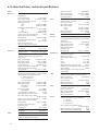
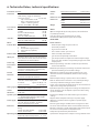
6. Technische Daten, technical specications
Inputs
channel 1 Instrument / line input, high impedance,
unbalanced
Stereo jack socket*: ¼“ (6.35 mm)
Nom. input voltage: 100 mV (–20 dBV)
High/low (attenuator) switch: –10 dB
Min. input voltage:
high: 22 mV (–33 dBV)
low: 68 mV (–23 dBV)
Max. input voltage (THD = 1%):
high: 3.5 V (+11 dBV)
low: 5 V (+14 dBV)
Input impedance: 2.2 MΩ || 350 pF
Signal / noise ratio (A-weighted): 95 dB
Equivalent input noise voltage
(A-weighted): 1.8 µV (–115 dBV)
Phantom power (switchable): 9 V DC
Load current: max. 100 mA
Short circuit protected.
*Ring used for phantom power.
clip indicator
Headroom: approx. 6 dB
channel 2 Switchable input with line and microph. mode
Combo socket: XLR + jack ¼” (6.35 mm)
line mode (jack input only)
Instrument / line input, high impedance,
unbalanced
Nom. input voltage: 100 mV (–20 dBV)
Min. input voltage: 27 mV (–31 dBV)
Max. input voltage: 7 V (+17 dBV)
Input impedance: 2.2 MΩ || 350 pF
Signal / noise ratio (A-weighted): 92 dB
Equivalent input noise voltage
(A-weighted): 0 2.7 µV (– 111 dBV)
mic mode
Microphone input, XLR (balanced), stereo jack
(balanced), mono jack (unbalanced)
1 / sleeve = ground,
2 / tip = positive (+),
3 / ring = negative (–)
Nom. input voltage: 10 mV (–40 dBV)
Min. input voltage: 3.3 mV (–50 dBV)
with option: 5.8 mV (–45 dBV)
(see notes)
Max. input voltage: 1 V (0 dBV)
with option: 1.6 V (+4 dBV)
Input impedance (balanced): 1.2 kΩ
Input impedance (unbalanced): 2.7 kΩ
Voice lter (referred to 10 kHz):
–10 dB at 270 Hz
Signal / noise ratio (A-weighted): 80 dB
Equivalent input noise voltage
(A-weighted): 1 µV (–120 dBV)
Phantom power (XLR only): 48 V
Supply resistors: 6.8 kΩ
Load current: max. 10 mA
clip indicator
Headroom: approx. 6 dB
return
Input for external parallel eect loop (send /
return), or supplementary input
Mono jack socket: ¼” (6.35 mm)
Nom. input voltage: 320 mV (–10 dBV)
Max. input voltage: 5 V (+14 dBV)
Input impedance: 20 kΩ
aux in
Auxiliary input, e.g. for CD
Stereo jack socket: 3.5 mm
Nom. input voltage: 500 mV (–6 dBV)
Min. input voltage,
stereo: 100 mV (–20 dBV)
mono: 200 mV (–14 dBV)
Max. input voltage: 4 V (+12 dBV)
Input impedance: 22 kΩ
Output
line out
Preamplier output post master, tone controls,
and eects
Mono jack socket: ¼” (6.35 mm)
Nom. output voltage: 700 mV (–3 dBV)
Output impedance: 100 Ω
Min. load impedance: 2 kΩ
Residual noise
(A-weighted): 4.5 µV (–107 dBV)
headphones
Headphones output
Stereo jack socket: ¼” (6.35 mm)
Output power (THD < 1 %):
8 Ω 2 x 2 mW
32 Ω 2 x 7 mW
2000 Ω 2 x 50 mW
Output impedance (per channel): 1000 Ω
Residual noise (A-weighted), referred to rated
output power: –94 dB
When plugged in, the internal speaker is
switched o.
send Output pre master, post tone controls, for
external parallel eect loop (send / return)
Mono jack socket: ¼” (6.35 mm)
Nom. output voltage
(pan centered): 300 mV (–10 dBV)
Output impedance: 47 Ω
Min. load impedance: 2 kΩ
tuner Tuner output, post tone controls,
pre eects and master
Mono jack socket: ¼” (6.35 mm)
Nom. output voltage: 100 mV (–20 dBV)
Output impedance: 47 Ω
Min. load impedance: 2 kΩ
DI-out Balanced, non-isolated XLR output, post tone
controls, switchable pre or post eects
1 = ground,
2 = positive (+),
3 = negative (–)
Nom. output voltage (dierential):
41 mV (–28 dBV)
Output impedance (per terminal): 47 Ω
Min. load impedance (dierential): 1 kΩ

15
6. Technische Daten, technical specications
Footswitch connector
footswitch Connector for a dual footwitch
(dual, latching, toggle on-o switch)
Stereo jack socket: ¼” (6.35 mm)
Tip = internal eect on/o
Ring = external eect on/o
Sleeve = common (ground)
Function: Switch ON = eect OFF
Tone controls
channel 1 colour at 700 Hz –3 dB
at 8 kHz +10 dB
bass at 100 Hz (shelf type) ± 8 dB
middle at 800 Hz ±6 dB
treble at 10 kHz (shelf type) ±8 dB
channel 2 bass at 100 Hz (shelf type) ±8 dB
treble at 10 kHz (shelf type) ±11 dB
Eects
Internal eect Digital eect processor
1 Reverb
2 Reverb with longer predelay
3 Delay (320 ms, repetitive)
4 Chorus
External eect Parallel eect loop, see send and return
eects pan Blends the eects (internal and external) bet-
ween channels 1 and 2, with reverse direction
of rotation for the external eects.
Power amp
Construction Monolithic IC with DMOS output
Rating Output power (THD = 1%) 200 W / 8 Ω
Continuous output power is determined by
the limiter, see limiter threshold.
General
Distortion THD + N (6 W / 4 Ω) < 0.1%
measured at loudspeaker terminals
Noise Residual noise (A-weighted),
referred to rated output power: –94 dB
Acoustical: approx. 17 dB (A) / 1 m
Signal / noise ratio: see input specs
Analog signal processing
Subsonic lter, adaptive peak limiter
Limiter
threshold 50 W / 4 Ω
Speaker system 2-way system, 8” (200 mm) low-midrange
+ 1” (25 mm) dome tweeter, light-weight
neodymium alloy magnets
Power supply Mains voltage (depending on model):
100, 120, 220, 230, or 240 V~, 50–60 Hz
Power consumption: max. 120 W
Mains fuse Size 5 x 20 mm
Rating
for 220, 230, 240 V models: T 1A L 250V
for 100, 120 V models: T 2A L 250V
Operating temperature
Permissible ambient temperature 0…35 °C
Cabinet Birch plywood, thickness: 12 mm (0.47“)
Finish Waterbased acrylic, black spatter nish
Dimensions and weight
Dimensions Height 320 mm (12.6“)
Width 326 mm (12.9“)
Depth 282 mm 11.1“)
Weight 10 kg (22.1lbs)
NOTES
Options congurable by internal jumpers (refer modication
to qualied personnel):
Low-gain option (more headroom) for mic input
Deactivation of 48 V phantom power for mic input
DEFINITIONS
Rated conditions
• Nominal input voltage at input under test
• master fully clockwise
• high / low and colour o
• bass / middle / treble / pan centered
• eects level fully anticlockwise
• gain of unused inputs fully anticlockwise
• gain of input under test adjusted to nominal output voltage
at line out. (This condition corresponds by design to the rated
output power.)
Nominal input voltage: Standard condition for specications,
if not stated otherwise.
Minimum input voltage: Input voltage required for nominal out-
put with maximum gain and volume settings.
Maximum input voltage: Input voltage that does not cause
distortion more than rated THD+N, suitable control settings
provided.
Nominal output voltage or power refer to rated conditions.
THD + N: Total harmonic distortion + noise, with input voltage
reduced by 10 dB after setting up rated conditions.
Signal / noise ratio: Ratio of output voltage at rated conditions to
output noise voltage with input shorted.
Equivalent input noise voltage: Noise voltage at loudspeaker ter-
minals divided by gain of amplier. Input shorted after setting
up rated conditions.
Residual noise: Output noise with minimal gain and volume
settings.
Adaptive limiter: Adaptive with respect to power supply.
Maintains constant headroom regardless of power supply
uctuations.
General: Signal voltages are RMS values. Test signal sine 1 kHz
sine unless stated otherwise. Noise measured from 20 Hz to 20
kHz. Noise stated for a specic input implies that all other inputs
are not used. Sound pressure level (SPL) based on
loudspeaker specication by manufacturer.
Specications and appearance subject to change without notice.

16
Sales
Africa, America, Asia, Oceania
aer music gmbh
Haberstrasse 46
D-42551 Velbert
aer amplier gmbh
Haberstrasse 46
D-42551 Velbert
info@aer-amplier.com
Sales
Europe
www.aer-music.de
Version: 00600122
-
 1
1
-
 2
2
-
 3
3
-
 4
4
-
 5
5
-
 6
6
-
 7
7
-
 8
8
-
 9
9
-
 10
10
-
 11
11
-
 12
12
-
 13
13
-
 14
14
-
 15
15
-
 16
16


AER compact XL Bedienungsanleitung
- Kategorie
- Musikausrüstung
- Typ
- Bedienungsanleitung
in anderen Sprachen
- English: AER compact XL Owner's manual
Verwandte Artikel
-
AER COMPACT MOBILE 2 Bedienungsanleitung
-
AER CompactClassicPro Bedienungsanleitung
-
-
-
-
-
-
-
-