
1. Allgemeine Angaben
Die Originalbetriebsanleitung ist in deutscher Sprache
verfasst.
Die Betriebsanleitungen anderer Sprachen wurden aus
dem Deutschen übersetzt.
1.1 Gültigkeit der Anleitung
Diese Anleitung gilt für das Ersatz-Ventil Regudis
W-HTE Anschluss- und Absperrset.
1.2 Lieferumfang
Prüfen Sie Ihre Lieferung auf Transportschäden und
Vollständigkeit.
Der Lieferumfang umfasst:
• Ersatz-Ventil für Regudis W-HTE Anschluss- und
Absperrset
• 3 x Farbring (in den Farben rot, blau und grün. Zur
Kennzeichnung des Anschlusses)
• Dichtring
• Sicherungsfeder
• Betriebsanleitung
1.3 Kontakt
OVENTROP GmbH & Co. KG
Paul-Oventrop-Straße 1
59939 Olsberg
DEUTSCHLAND
www.oventrop.com
Technischer Kundendienst
Telefon: +49 (0) 29 62 82-234
1.4 Verwendete Symbole
Kennzeichnet wichtige Informationen und
weiterführende Ergänzungen.
f Handlungsaufforderung
• Aufzählung
1.
2.
bis X.
Z Ergebnis der Handlung
2. Sicherheitsbezogene Informationen
2.1 Bestimmungsgemäße Verwendung
Die Betriebssicherheit ist nur bei
bestimmungsgemäßer Verwendung des Produktes
gewährleistet.
Das Ersatz-Ventil ist für den Einbau im Anschluss- und
Absperrset für die Wohnungsstation Regudis W-HTE
vorgesehen.
Jede darüber hinausgehende und/oder andersartige
Verwendung gilt als nicht bestimmungsgemäß.
Ansprüche jeglicher Art gegen den Hersteller und/oder
seine Bevollmächtigten wegen Schäden aus nicht
bestimmungsgemäßer Verwendung können nicht
anerkannt werden.
Zur bestimmungsgemäßen Verwendung zählt auch die
korrekte Einhaltung dieser Anleitung.
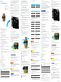
Abb. 1: Einbauort
2.2 Sicherheitseinrichtungen
2.2.1 Farbringe
Zur Kennzeichnung der Anschlüsse liegen dem Ersatz-
Ventil Farbringe in den Farben rot, blau und grün bei.
Verwenden Sie den roten Farbring zur Kennzeichnung
des Vorlaufs. Verwenden Sie den blauen Farbring zur
Kennzeichnung des Rücklaufs. Verwenden Sie den
grünen Farbring zur Kennzeichnung des
Trinkwasserkreises.
Der jeweilige Farbring wird an der entsprechenden
Stelle aufgesteckt.
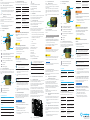
Abb. 2: Farbring montieren
2.3 Warnhinweise
Jeder Warnhinweis enthält folgende Elemente:
SIGNALWORT
Art und Quelle der Gefahr!
Mögliche Folgen, wenn die Gefahr eintritt bzw.
der Warnhinweis ignoriert wird.
!
Möglichkeiten zur Vermeidung der Gefahr.
einer Situation ausgeht.
WARNUNG
Kennzeichnet eine mögliche Gefahr mit mittlerem
Risiko. Wenn die Situation nicht vermieden wird, sind
möglicherweise Tod oder schwere
Körperverletzungen die Folge
VORSICHT
Kennzeichnet eine mögliche Gefahr mit geringerem
Risiko. Wenn die Situation nicht vermieden wird, sind
leichte und reversible Körperverletzungen die Folge.
ACHTUNG
Kennzeichnet eine Situation, die möglicherweise
Sachschäden zur Folge haben kann, wenn sie nicht
vermieden wird.
2.4 Sicherheitshinweise
Wir haben dieses Produkt gemäß aktueller
Sicherheitsanforderungen entwickelt.
Beachten Sie folgende Hinweise zum sicheren
Gebrauch.
2.4.1 Gefahr durch unzureichende
Personalqualikation
Arbeiten an diesem Produkt dürfen nur dafür
fachlichen Ausbildung und Erfahrungen sowie
Kenntnisse der einschlägigen rechtlichen Vorschriften
in der Lage, Arbeiten am beschriebenen Produkt
fachgerecht auszuführen.
Betreiber
Der Betreiber muss von einem Fachhandwerker in die
Bedienung eingewiesen werden.
2.4.2 Verletzungsgefahr bei unsachgemäßer
Arbeit
Kantige Bauteile, Spitzen und Ecken am und im Produkt
können Verletzungen verursachen.
!
Sorgen Sie vor Beginn der Arbeiten für
ausreichenden Platz.
!
Gehen Sie mit offenen oder scharfkantigen
Bauteilen vorsichtig um.
2.4.3 Verfügbarkeit der Betriebsanleitung
Jede Person, die mit diesem Produkt arbeitet, muss
diese Anleitung und alle mitgeltenden Anleitungen
gelesen haben und anwenden.
Die Anleitung muss am Einsatzort des Produktes
verfügbar sein.
!
Geben Sie diese Anleitung und alle mitgeltenden
Anleitungen an den Betreiber weiter.
3. Technische Beschreibung
3.1 Aufbau
5
2
4
3
1
Abb. 3: Aufbau
1Gewindeanschluss G¾ Außengewinde
(Anschluss an Station)
2Gewindeanschluss Rp¾ Innengewinde
(Anschluss an Rohrnetz)
3Farbring zur Markierung des
Anschlusses
4Griff
5Sicherungsfeder
3.2 Funktionsbeschreibung
Durch Betätigung des Griffs wird die angeschlossene
Leitung durch eine Keramikscheibe im Innern des
Ventils abgesperrt. Die Markierung auf dem Gehäuse
oder geschlossen wird.
12
Abb. 4: Griffstellung geöffnet / geschlossen
1Griffstellung geöffnet
2Griffstellung geschlossen
3.3 Technische Daten
Allgemein
Nenndurchmesser
max. Betriebsdruck ps
max. Betriebstemperatur
ts
Material
Gehäuse Messing
Keramikscheibe Keramik
Dichtung PTFE / EPDM / Silikon
4. Transport und Lagerung
Transportieren Sie das Produkt in der
Originalverpackung.
Lagern Sie das Produkt unter folgenden Bedingungen:
Temperaturbereich
Relative
Luftfeuchtigkeit
Partikel Trocken und staubgeschützt
Mechanische
Geschützt vor
mechanischer
Erschütterung
Strahlung
Geschützt vor UV-Strahlung
und direkter
Sonneneinstrahlung
Nicht zusammen mit
Lösungsmitteln,
Chemikalien, Säuren,
Kraftstoffen u.ä. lagern
5. Montage
WARNUNG
Verletzungsgefahr durch Armaturen unter
Druck!
Unter Druck austretende Medien können zu
Verletzungen führen.
!
Führen Sie alle Installationsarbeiten immer nur an
einer drucklosen Anlage aus.
!
Tragen Sie eine Schutzbrille.
VORSICHT
Verbrühungsgefahr durch heiße Medien!
Wenn die Station in Betrieb war, dann besteht
Verbrühungsgefahr durch ungewolltes
Austreten von Heißwasser oder Wasserdampf.
!
Lassen Sie die Anlage abkühlen.
!
Tragen Sie eine Schutzbrille.
VORSICHT
Verbrennungsgefahr an heißen Bauteilen!
Das Berühren heißer Bauteile kann zu
Verbrennungen führen.
!
Tragen Sie Schutzhandschuhe.
Vor der Montage des Ersatz-Ventils müssen
Sie das vorhandene Ventil im Anschluss-
und Absperrset demontieren
1 Ziehen Sie die Sicherungsfeder unterhalb des
Halteblechs vom vorhandenen Ventil ab, um das
Ventil im Halteblech zu lösen.
2 Entnehmen Sie das vorhandene Ventil aus dem
Halteblech.
Halten Sie einen Lappen bereit, um
austretendes Wasser aufzufangen.
3 Schieben Sie das Ersatz-Ventil von vorne in das
Halteblech. Richten Sie das Ventil so aus, dass die
Markierung der Griffstellung (siehe Abb. 4) gut
lesbar ist.
4 Schieben Sie die Sicherungsfeder unterhalb des
Halteblechs über das Ventil, um das Ventil im
6. Demontage und Entsorgung
Wenn das Gebrauchsende des Produktes erreicht oder
ein irreparabler Defekt vorliegt, muss es demontiert
und umweltgerecht entsorgt bzw. müssen die
Bestandteile wiederverwertet werden.
ACHTUNG
Verschmutzungsgefahr für die Umwelt!
Nicht fachgerechte Entsorgung kann zu
Umweltschäden führen.
!
Entsorgen Sie Verpackungsmaterial
umweltgerecht.
!
Führen Sie Bestandteile möglichst der
Wiederverwertung zu.
!
Entsorgen Sie nicht wiederverwertbare
Bestandteile den lokalen Vorschriften
entsprechend.
1. Allgemeine Angaben
2. Sicherheitsbezogene Informationen
3. Technische Beschreibung
4. Transport und Lagerung
5. Montage
6. Demontage und Entsorgung
134478080-V01.04.2022
Sicherheits- und
Installationshinweise
Safety and
installation advice
Consignes de sécurité et
de montage
Ersatz-Ventil für Regudis W-HTE
Anschluss- und Absperrset
dwelling station.
Any use beyond and/or different from this is
considered unintended use.
Claims of any kind against the manufacturer and/or his
authorised representatives for damage resulting from
unintended use cannot be recognised.
Intended use also includes correct compliance with
these instructions.
Fig. 1: Installation position
2.2 Safety devices
2.2.1 Colour rings
The replacement valve comes with colour rings in red,
blue and green to identify the connections.
Use the red colour ring to identify the supply. Use the
blue colour ring to identify the return. Use the green
colour ring to identify the potable water circuit.
The respective colour ring is attached at the
appropriate position.
Fig. 2: Mounting of the colour rings
2.3 Warnings
Each warning contains the following elements:
SIGNAL WORD
Type and source of danger!
Possible consequences if the danger occurs or
the warning is ignored.
!
Ways to avoid the danger.
a situation.
WARNING
Indicates a possible danger with moderate risk. If the
situation is not avoided, death or serious bodily
injuries may result.
CAUTION
Indicates a possible danger with lower risk. If the
situation is not avoided, minor and reversible bodily
injuries will result.
NOTICE
Indicates a situation that can potentially result in
damage to property if not avoided.
2.4 Safety instructions
We have developed this product in accordance with
current safety requirements.
Observe the following instructions for safe use.
2.4.1 Dangerduetoinsufcientpersonnel
qualication
Work on this product may only be carried out by
Due to their professional training and experience as
well as knowledge of the relevant legal regulations,
work on the described product in a professional
manner.
DE
FR
EN
DE
1. General information
The original operating instructions are written in
German.
The operating instructions in other languages have
been translated from German.
1.1 Validity of the instructions
These instructions are valid for the replacement valve
for the connection and shutoff set for the Regudis
W-HTE dwelling station.
1.2 Scope of delivery
Check your delivery for transport damage and
completeness.
The scope of delivery includes:
• Replacement valve for the connection and shutoff
set for the Regudis W-HTE dwelling station
• 3 x colour ring (red, blue and green for
• Sealing ring
• Retaining spring
• Operating instructions
1.3 Contact
OVENTROP GmbH & Co. KG
Paul-Oventrop-Straße 1
59939 Olsberg
GERMANY
www.oventrop.com
Technical service
Phone: +49 (0) 29 62 82-234
1.4 Symbols used
Highlights important information and
further additions.
f Action required
• List
1.
2.
Z Result of action
2. Safety-related information
2.1 Intended use
Operational safety is only guaranteed if the product is
used as intended.
The replacement valve is intended for installation in the
connection and shutoff set for the Regudis W-HTE
EN
1. General information
2. Safety-related information
3. Technical description
4. Transport and storage
5. Mounting
6. Removal and disposal

Operator
The operator must be instructed in the operation of the
product by specialist tradespeople.
2.4.2 Risk of injury from improper work
Angular components, points and corners on and in the
product can cause injuries.
!
!
Handle open and sharp-edged components with
care.
2.4.3 Availability of the operating
instructions
Every person who works with this product must have
read and apply this manual and all applicable
instructions.
The instructions must be available at the place of use
of the product.
!
Pass on these instructions and all applicable
instructions to the operator.
3. Technical description
3.1 Design
5
2
4
3
1
Fig. 3: Design
1
(connection to the station)
2
(connection to the pipework)
3
connection
4Handle
5Retaining spring
3.2 Functional description
By operating the handle, the connected pipe is shut off
by a ceramic disc inside the valve. The marking on the
closed.
12
Fig. 4: Handle position open / closed
1Handle position open
2Handle position closed
3.3 Technical data
General information
Nominal diameter
Max. operating pressure ps
Max. operating temperature ts
Material
Housing Brass
Ceramic dis Ceramic
Seal PTFE / EPDM /
Silicon
2.2 Dispositifs de sécurité
2.2.1 Bagues colorées
Des bagues colorées en rouge, bleu et vert sont
raccordements.
E.C.S.
prévu.
Fig. 2: Montage des bagues colorées
2.3 Avertissements
Chaque avertissement comprend les éléments
MOT DE SIGNALISATION
Nature et source du danger!
Conséquences possibles en cas de survenue
!
Moyens de prévention du danger.
danger que représente une situation.
AVERTISSEMENT
Signale un danger possible avec un risque moyen. La
mort ou des blessures corporelles graves.
ATTENTION
Signale un danger possible avec un risque moindre.
blessures corporelles mineures et réversibles.
AVIS
2.4 Consignes de sécurité
Nous avons développé ce produit conformément aux
exigences de sécurité actuelles.
Respecter les consignes suivantes pour une utilisation
en toute sécurité.
2.4.1 Dangerdûàunequalication
insufsantedupersonnel
Les travaux sur ce produit ne doivent être effectuées
De par leur formation et leur expérience
professionnelles ainsi que leur connaissance des
dispositions légales en vigueur, les professionnels
produit décrit de manière professionnelle.
Exploitant
2.4.2 Risque de blessure en cas de travail non
conforme
Les composants anguleux, les pointes et les coins sur
et dans le produit peuvent provoquer des blessures.
!
travaux.
!
Manipuler avec précaution les composants ouverts
ou à arêtes vives.
2.4.3 Disponibilité de la notice d’utilisation
Toute personne qui travaille avec ce produit doit avoir
lu et appliquer cette notice et toutes les autres notices
applicables.
produit.
!
Transmettre cette notice et toutes les notices
3. Description technique
3.1 Conception
5
2
4
3
1
Fig. 3: Conception
1
(raccordement à la station)
2
(raccordement à la tuyauterie)
3
raccordement
4Poignée
5Circlip
3.2 Description du fonctionnement
En actionnant la poignée, la conduite raccordée est
robinet. Le marquage sur le corps indique dans quel
sens le débit est ouvert ou fermé.
12
Fig. 4: Position ouverte / fermée de la poignée
1Position ouverte de la poignée
2Position fermée de la poignée
3.3 Données techniques
Généralités
Diamètre nominal
Pression de service max.
ps
Température de service
max. ts
Matériaux
Corps Laiton
Disque en céramique Céramique
Joint PTFE / EPDM / Silicone
4. Transport et stockage
Stocker le produit dans les conditions suivantes :
Plage de
température
Humidité relative de
Particules Stocker dans un endroit sec
et protégé de la poussière
mécaniques
Protégé contre les chocs
mécaniques
Rayonnement
Protégé du rayonnement
UV et du rayonnement
solaire direct
Ne pas stocker avec des
solvants, des substances
chimiques, des acides, des
carburants et similaires
5. Montage
AVERTISSEMENT
Risque de blessure par des robinetteries sous
pression!
!
le système est hors pression.
!
Porter des lunettes de protection.
ATTENTION
Risque de brûlure par des uides chauds!
Si la station a été en fonctionnement, il y a
risque de brûlure dû à une fuite involontaire
!
!
Porter des lunettes de protection.
ATTENTION
Risque de brûlure sur les composants
chauds!
Le contact avec des composants chauds peut
!
Porter des gants de protection.
Avant de monter le robinet de rechange,
vous devez démonter le robinet existant
5 Retirer le circlip sous la tôle de maintien du
tôle de maintien.
6 Enlever le robinet existant de la tôle de maintien.
Ayez un chiffon à portée de main pour
7
tôle de maintien. Aligner le robinet de manière à
ce que le marquage de la position de la poignée
(voir Fig. 4) soit bien lisible.
8 Faire glisser le circlip sous la tôle de maintien par-
de maintien.
6. Démontage et traitement des déchets
présente un défaut irréparable, il doit être démonté et
composants doivent être recyclés.
AVIS
Risque de pollution pour l’environnement!
des dommages environnementaux.
!
!
Si possible, recycler les composants.
!
Éliminer les composants non recyclables
conformément aux réglementations locales.
4. Transport and storage
Transport the product in its original packaging.
Store the product under the following conditions:
Temperature range
Relative air humidity
Particles Store in a dry and dust-
protected place
Mechanical
Protected from mechanical
shock
Radiation Protected from UV rays and
direct sunlight
Do not store together with
solvents, chemicals, acids,
fuels or similar substances
5. Mounting
WARNING
Risk of injury from pressurised components!
Media escaping under pressure can cause
injuries.
!
Only carry out installation work when the system
is depressurised.
!
Wear safety goggles.
CAUTION
Risk of scalding due to hot media!
If the station has been in operation, there is a
risk of scalding due to unintentional escape of
hot water or water steam.
!
Allow the system to cool down.
!
Wear safety goggles.
CAUTION
Risk of burns on hot components!
Touching hot components can cause burns.
!
Wear safety gloves.
must dismantle the existing valve in the
connection and shutoff set.
1 Pull the retaining spring below the retaining plate
off the existing valve to release the valve in the
retaining plate.
2 Remove the existing valve from the retaining
plate.
Have a cloth available to catch any water that
escapes.
3 Push the replacement valve into the retaining
plate from the front. Align the valve so that the
handle position marking (see Fig. 4) is clearly
visible.
4 Slide the retaining ring underneath the retaining
plate.
6. Removal and disposal
When the product reaches the end of its service life or
has an irreparable defect, it must be dismantled and
disposed of in an environmentally friendly manner or
the components must be recycled.
NOTICE
Risk of environmental pollution!
Incorrect disposal can lead to environmental
damage.
!
Dispose of packaging materials in an
environmentally friendly manner.
!
If possible, recycle the components.
!
Dispose of non-recyclable components according
to local regulations.
134478080-V01.04.2022
1. Généralités
1.1 Validité de la notice
1.2 Composants fournis
Les composants fournis sont les suivants :
• Robinet de rechange pour jeu de raccordement et
• 3 x bague colorée (en rouge, bleu et vert pour
•
• Circlip
•
1.3 Contact
OVENTROP GmbH & Co. KG
Paul-Oventrop-Straße 1
59939 Olsberg
ALLEMAGNE
www.oventrop.com
Service technique
Téléphone : +49 (0) 29 62 82-234
1.4 Symboles utilisés
Indique des informations importantes et
des explications complémentaires.
f
• Énumération
1.
2.
Z
2. Informations relatives à la sécurité
2.1 Utilisation conforme
est utilisé conformément à sa destination.
Le robinet de rechange est prévu pour être monté dans
Toute utilisation dépassant ce cadre et/ou différente
fabricant et/ou ses représentants autorisés pour des
peuvent pas être reconnues.
des recommandations de cette notice.
Fig. 1: Position de montage
FR
1. Généralités
2. Informations relatives à la sécurité
3. Description technique
4. Transport et stockage
5. Montage
6. Démontage et traitement des déchets
-
 1
1
-
 2
2


in anderen Sprachen
- English: Oventrop 1344780 Owner's manual
- français: Oventrop 1344780 Le manuel du propriétaire
Verwandte Artikel
-
Oventrop 1344685 Bedienungsanleitung
-
-
-
Oventrop 1341031 Bedienungsanleitung
-
Oventrop 1341031 Bedienungsanleitung
-
-
Oventrop 1060303 Bedienungsanleitung
-
Oventrop 1146064 Bedienungsanleitung
-
-