Velp Scientifica OHS Advanvce Benutzerhandbuch
- Typ
- Benutzerhandbuch

1
Instruction Manual
Manuale di istruzioni
Manuel d’instructions
Manual de instrucciones
Bedienungsanleitung
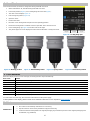
OHS 200 ADVANCE Overhead stirrers
F20100480, F20110480
OHS 100 ADVANCE Overhead stirrers
F20100481, F20110481
OHS 60 ADVANCE Overhead stirrers
F20100482, F20110482
General Information / Informazioni Generali / Informations Générales / Información General / Allgemeine Hinweise
Before using the unit, please read the following instruction manual carefully.
Prima dell’utilizzo dello strumento si raccomanda di leggere attentamente il seguente manuale operativo.
Avant d’utiliser l’instrument, il est recommandé de lire attentivement le présent manuel d’instructions.
Antes de utilizar el instrumento, le recomendamos que lea con atención el siguiente manual de funcionamiento.
Bitte lesen Sie vor Inbetriebnahme des Geräts diese Bedienungsanleitung sorgfältig durch
Do not dispose of this equipment as urban waste, in accordance with EEC directive 2002/96/CE.
Non smaltire l’apparecchiatura come rifiuto urbano, secondo quanto previsto dalla Direttiva 2002/96/CE.
Ne pas recycler l’appareil comme déchet solide urbain, conformément à la Directive 2002/96/CE.
No tirar el aparato en los desechos urbanos, como exige la Directiva 2002/96/CE.
Dieses Gerät unterliegt der Richtlinie 2002/96/EG und darf nicht mit dem normalen Hausmüll entsorgt werden.
This unit must be used for laboratory applications indoor only. The manufacturer declines all responsibility for any use of the unit that
does not comply with these instructions. If the product is used in a not specified way by the manufacturer or with not specified
accessories, product's safety may be compromised.
Questo strumento deve essere utilizzato solo per applicazioni di laboratorio per uso interno. La società produttrice declina ogni
responsabilità sull’impiego non conforme alle istruzioni degli strumenti. Se il prodotto viene utilizzato in un modo non specificato o con
accessori non specificati dal costruttore stesso, la sicurezza del prodotto potrebbe essere compromessa.
Cet instrument ne peut être utilisé pour les applications de laboratoire à l'intérieur seulement. Le fabriquant décline toute
responsabilité en cas d’utilisation non conforme aux instructions concernant ces instruments. Si le produit est utilisé d'une manière non
spécifiée par le fabricant ou accessoires non spécifiés, la sécurité du produit peut être compromise.
Este dispositivo sólo debe utilizarse para aplicaciones de laboratorio para uso interno.
El fabricante declina toda responsabilidad por el uso no conforme a las instrucciones de los dispositivos. Si se utiliza el producto de una
manera no especificada o con accesorios no especificados de el fabricante, la seguridad del producto puede estar comprometida.
Dieses Gerät muss nur für Laboranwendungen verwendet werden.Der Hersteller lehnt jede Haftung für unsachgemäße Verwendung
oder Nichtbeachtung dieser Bedienungsanleitung ab. Wenn das Produkt in einer Weise verwendet wird, die nicht vom Hersteller oder mit
unsachgemäßer Zubehör angegeben , kann das Produkt die Sicherheit beeinträchtigt werden.
This unit has been designed and manufactured in compliance with the following standards:
Lo strumento è stato progettato e costruito in accordo con le seguenti norme:
L’instrument a été conçu et fabriqué conformément aux normes suivantes:
El dispositivo se ha sido diseñado y fabricado de acuerdo con las siguientes normas:
Das Gerät wurde in Übereinstimmung mit folgenden Normen entwickelt und gebaut:
Safety requirements for electrical equipment for measurement, control and for laboratory use
Prescrizioni di sicurezza per apparecchi elettrici di misura, controllo e per l’utilizzo in laboratorio
Règles de sécurité pour appareils électriques de mesurage, de régulation et de laboratoire
IEC/EN 61010-1 IEC/EN
61010-2-051

2
Prescripciones de seguridad para equipos eléctricos de medición, control y su uso en laboratorio
Sicherheitsbestimmungen für elektrische Mess-, Steuer-, Regel- und Laborgeräte
Electrical equipment for laboratory use
UL 61010-1
General requirement - Canadian electrical code
CAN/CSA-C22.2 No.61010-1
VELP reserves the right to modify the characteristics of its products with the aim to constantly improving their quality.
Nell’impegno di migliorare costantemente la qualità dei prodotti, VELP si riserva la facoltà di variarne le caratteristiche.
Dans le but d’améliorer constamment la qualité de ses produits, VELP se réserve le droit d’apporter des modifications aux
caractéristiques de ceux-ci.
VELP se reserva el derecho de modificar las características de sus productos con el objetivo de mejorar constantemente su calidad.
VELP behält sich zum Zwecke der ständigen Verbesserung der Produktqualität das Recht auf Änderung der Geräteeigenschaften vor.
Safety Regulations / Norme di Sicurezza / Consignes de Securité / Advertencias de Seguridad / Sicherheitshinweise
The plug disconnects the instrument. Therefore, place the instrument where it can be quickly disconnected. / La spina è il mezzo di
disconnessione dell’apparecchio. Pertanto, non posizionare l’apparecchio in modo che sia difficile azionare il mezzo di disconnessione. /
Le bouchon est le moyen de déconnexion de l'appareil. Par conséquent, placer l'appareil où il peut être rapidement débranché. / El tapón
es el medio de desconexión del dispositivo. No coloque el dispositivo en una forma que es difícil de desconectar. / Der Stecker trennt das
Gerät. Daher Stellen Sie das Instrument, wo es schnell getrennt werden kann.
The values indicated on the rating plate of the instrument must correspond to those of the power supply.
I valori di tensione indicato sulla targhetta del modello e quello di rete devono coincidere.
Les valeurs indiquées sur la plaque signalétique de l'appareil doivent correspondre à ceux de l'alimentation.
Los valores de tensión indicados en la placa y que de la red debe ser los mismos.
Die angegebene Spannung Wert auf dem Typenschild und das Netzwerk muss gleich sein.
Position the instrument on a flat surface, with a distance from the wall of 30 cm (at least).
Posizionare lo strumento su superfici piane, ad una distanza dalle pareti di almeno 30 cm.
Positionner l'appareil sur une surface plat, avec une distance de la paroi de 30 cm (au moins).
Coloque la unidad sobre una superficie plana, con una distancia de la pared de 30 cm (por lo menos).
Stellen Sie das Gerät auf einer ebenen Fläche mit einem Abstand zur Wand von 30 cm (mindestens).
Fasten the unit to the support rod (A00000366 or A00000369) using the double clamp (A00001301). Secure the receptacle using the
ribbon clamp (A00001302).
Fissare saldamente lo strumento allo stativo (A00000366 o A00000369) mediante il morsetto doppio (A00001301) e il recipiente di
agitazione con l’apposita cinghia (A00001302).
Fixez l'unité à le statif (A00000366 ou A00000369) con le noix de fixation double (A00001301). Fixer le réceptacle à l'attache souple avec
ruban (A00001302).
Asegurar firmemente la herramienta a la barra de soporte (A00000366 o A00000369) con la abrazadera doble (A00001301) y el
recipiente con la abrazadera de cinta (A00001302).
Befestigen Sie das Gerät an der H-Stativ (A00000366 oder A00000369) mit der Kreuzmuffe (A00001301). Sichern Sie die Aufnahme mit
der Spannhalter (A00001302).
Safe working conditions are ensured only when the accessories described in the dedicated chapter are used.
Il funzionamento sicuro è garantito soltanto con gli accessori descritti nel relativo capitolo.
Conditions de travail sûres sont assurées que lorsque les accessoires décrits dans le chapitre dédié sont utilisés.
El funcionamiento es seguro sólo con los accesorios descritos en el capítulo correspondiente.
Sichere Arbeitsbedingungen sind gewährleistet, wenn das Zubehör in dem Kapitel beschrieben verwendet werden.
The working speed set on the instrument must be such as to avoid wobbling and/or splashes.
Il numero di giri impostato deve escludere eventuali squilibri dell’agitatore e possibili spruzzi del prodotto agitato.
Le nombre de tours de l'ensemble agitateur doit exclure les déséquilibres et les éclaboussures du produit agité.
El número de revoluciones del agitador debe excluir cualquier desequilibrio y posible de salpicar de el producto agitado.
Die Arbeitsgeschwindigkeit des Gerätes muss gesetzt sein, wie Wackeln und / oder Spritzer zu vermeiden.
Do not use with explosive or dangerous materials for which the equipment is not designed. The stirrer must not be used in explosive
atmospheres, in bain-marie or to stir harmful liquids prior using protective measures according to the safety standards of the processed
products and/or in force in the laboratories including personal protective equipment and the presence of an extraction hood which ensures
at least 10-fold air change in accordance with the standards EN 14175 and DIN 12924.
Vietato l’uso con materiale esplosivo o pericoloso per cui l’apparecchio non è progettato. L’agitatore non può essere impiegato in
atmosfere esplosive, a bagno maria o per agitare liquidi pericolosi previo utilizzo di misure di protezione in accordo con le norme di
sicurezza dei prodotti in lavorazione e/o vigenti nei laboratori, compresi dispositivi di protezione individuale e la presenza di una cappa
aspirante che garantisca almeno 10 ricambi di aria in accordo con le norme EN 14175 e DIN 12924.
Ne pas utiliser avec des matières explosives et dangereuses pour lesquelles l'équipement n'est pas conçu. L'agitateur ne doit pas être
utilisé dans des atmosphères explosives, au bain-marie ou pour remuer des liquides nocifs avant l'utilisation de mesures de protection
selon les normes de sécurité des produits transformés et / ou en vigueur dans les laboratoires, y compris les équipements de protection
individuelle et la présence d'une extraction hotte assurant un renouvellement d'air d'au moins 10 fois conformément aux normes EN
14175 et DIN 12924.
No debe utilizarse con materiales explosivos y peligrosos para los que el equipo no está diseñado. El agitador no se debe usar en
atmósferas explosivas, en baño de maría o para agitar líquidos dañinos antes de usar medidas de protección de acuerdo con las normas
de seguridad de los productos procesados y / o vigentes en los laboratorios, incluido el equipo de protección personal y la presencia de
una extracción. Capucha que garantiza un cambio de aire de al menos 10 veces de acuerdo con las normas EN 14175 y DIN 12924.
Nicht mit explosivem Material zu verwenden, für die das Gerät nicht ausgelegt ist. Das Gerät kann nicht in explosionsgefährdeten
Bereichen eingesetzt werden, in einem Wasserbad oder zum Umrühren von schädlichen Flüssigkeiten verwendet werden, bevor
Schutzmaßnahmen gemäß den Sicherheitsnormen der verarbeiteten Produkte durchgeführt werden und / oder in den Laboratorien

3
einschließlich der persönlichen Schutzausrüstung und dem Vorhandensein einer Extraktion in Kraft sind Haube, die einen mindestens 10-
fachen Luftwechsel gemäß den Normen EN 14175 und DIN 12924 gewährleistet.
It is dangerous to run the unit with the stirring blade turning in free air. Always place the stirring shaft in the receptacle before turning the
unit on.
Il funzionamento con estremità dell’albero in rotazione libera è pericoloso. Per ragioni di sicurezza, quindi, inserire l’asta di agitazione nel
recipiente di agitazione prima di avviare lo strumento.
Il est dangereux de faire fonctionner l'unité avec la lame d'agitation tournant à l'air libre. Toujours placer la tige d'agitation dans le récipient
avant de mettre l'appareil en marche.
Es peligroso ejecutar la unidad con la paleta de agitación en el aire libre. Coloque siempre la varilla de agitación en el recipiente antes de
encender la unidad.
Es ist gefährlich, das Gerät mit dem Rührklinge Drehen in freier Luft laufen. Legen Sie immer die Rührwelle in der Aufnahme, bevor Sie
das Gerät einschalten.
It is responsibility of the user appropriately decontaminate the instrument in case of dangerous substances fall on or in it.
It is also responsibility of the user to use safety substances for cleaning or decontaminating, which do not react with internal parts of the
instrument or with the material contained in it. In case of doubts on the compatibility of a cleaning solution, contact the manufacturer or
local distributor.
E’ responsabilità dell’utilizzatore un’appropriata decontaminazione in caso di versamento di sostanze pericolose sul o dentro
l’apparecchio. E’ inoltre responsabilità dell’utilizzatore l’uso di sostanze decontaminanti o per la pulizia che non producano pericolo a
causa di reazioni con parti dell’apparecchio o con il materiale in esso contenuto. In caso di dubbio sulla compatibilità di un agente pulente
o decontaminante, contattare il produttore o un distributore locale.
Est responsabilité de l'utilisateur la décontamination en cas de déversement de matières dangereuses sur ou à l'intérieur de l'équipement.
Est responsabilité de l'utilisateur à utiliser des substances qui ne produisent pas de danger pour le nettoyage ou de décontamination, qui
ne réagissent pas avec les parties internes de l'appareil ou avec la matière qu'il contient. En cas de doute sur la compatibilité d'une
solution de nettoyage, contactez le fabricant ou le distributeur local.
Es responsabilidad del usuario una descontaminación adecuada en caso de derrame de sustancias peligrosas en o dentro el equipo. Es
responsabilidad del usuario también utilizar sustancias que no producen peligro para limpiar o descontaminar, que no reaccionan con las
partes internas del instrumento o con el material contenido en él. En caso de duda sobre la compatibilidad de una solución de limpieza,
póngase en contacto con el fabricante o el distribuidor local.
Der Benutzer ist dafür verantwortlich, für die ordnungsgemäße Dekontamination beim Freiwerden gefährlicher Stoffe auf oder im Inneren
des Geräts. Der Benutzer ist dafür verantwortlich, für die Reinigung oder Dekontaminierungsmitteln, die nicht mit internen Teile des
Gerätes oder mit dem Material in ihm enthaltenen reagieren. Im Zweifelsfall über die Vereinbarkeit einer Reinigungslösung den Hersteller,
den Vertreiber oder den Händler.
The solution may release toxic, dangerous or poisonous gases. Adequate safety measures must be taken, in accordance with the safety
regulations in force, including the presence of hood and personal protective equipment (masks, gloves, goggles, etc.).
Le sostanze potrebbero emanare gas tossici e/o pericolosi e/o velenosi. Adeguate misure di sicurezza devono essere prese, in accordo
con le normative di sicurezza dei prodotti in lavorazione e/o vigenti nei laboratori, compresa la presenza di cappe aspiranti e mezzi di
protezione individuale (maschere, guanti, occhiali, camici, ecc.).
La solution peut libérer gaz toxiques ou dangereux. Des mesures de sécurité adéquates doivent être prises, en conformité avec les
règlements de sécurité en vigueur, compris la présence de la hotte de laboratoire et équipements de protection individuelle (masques,
gants, lunettes, etc.).
Las sustancias pueden emitir tóxicos o peligrosos gas. Medidas de seguridad adecuadas deben ser adoptadas, de acuerdo con las
normas de seguridad vigentes en los laboratorios, incluyendo la presencia de la campana de humos y el equipo de protección personal
(mascarillas, guantes, gafas, etc.)
Die erwärmte Lösung kann giftige oder gefährliche Gase freigeben. Angemessene Sicherheitsmaßnahmen zu treffen, werden in
Übereinstimmung mit den geltenden Sicherheitsvorschriften, einschließlich der Anwesenheit Dunstabzug und persönliche
Schutzausrüstungen (Masken, Handschuhe, Schutzbrille, etc.).
Switch off the the stirring before opening chuck locking ring. Switch off the instrument before removing chuck.
Spegnere l’agitazione prima di aprire l’anello di serraggio mandrino. Spegnere lo strumento prima di rimuovere il mandrino.
Éteignez l'agitation avant d'ouvrir l'anneau de serrage de la broche. Éteignez l'instrument avant de retirer la broche.
Desconecte la agitación antes de abrir el anillo de bloqueo del mandril. Apague el instrumento antes de quitar el mandril.
Schalten Sie das Rührwerk aus, bevor Sie den Spannring öffnen. Schalten Sie das Gerät aus, bevor Sie das Futter entfernen.
The instrument contains a battery. Its substitution must be carried out by authorized Velp personnel only.
Lo strumento contiene una batteria. La sua sostituzione dovrà essere eseguita da parte di personale autorizzato Velp.
L'instrument contient une batterie. Son remplacement doit être effectué uniquement par du personnel autorisé de Velp.
El instrumento contiene una batería. Su sustitución debe ser realizada únicamente por personal autorizado de Velp.
Das Instrument enthält eine Batterie. Der Ersatz darf nur von autorisiertem Velp-Personal durchgeführt werden.
Contains FCC ID : YOPGS2101M / Contiene FCC ID: YOPGS2101M / Contient FCC ID: YOPGS2101M / Contiene FCC ID:
YOPGS2101M / Es enthält FCC ID : YOPGS2101M

4
Contents / Indice / Inhalt
1. INTRODUCTION .............................................................................................................................................................. 6
2. ASSEMBLY AND INSTALLATION ................................................................................................................................... 7
3. DISPLAY SYMBOLS ........................................................................................................................................................ 7
4. WORKING ........................................................................................................................................................................ 8
5. EXTERNAL CONNECTIONS ........................................................................................................................................... 9
6. VELP ERMES CONFIGURATION ................................................................................................................................. 10
7. MENU ............................................................................................................................................................................. 11
7.1 MENU STRUCTURE .................................................................................................................................................................. 11
7.2 METHODS .............................................................................................................................................................................. 12
7.2.1 Method set-up .................................................................................................................................................................... 12
7.3 GRAPH .................................................................................................................................................................................. 14
7.4 SAFETY .................................................................................................................................................................................. 14
7.5 SET-UP .................................................................................................................................................................................. 15
7.6 SERVICE ................................................................................................................................................................................. 15
8. SMARTCHUCKTM ........................................................................................................................................................... 17
9. ERROR MESSAGES ..................................................................................................................................................... 17
10. MAINTENANCE ............................................................................................................................................................. 17
11. TECHNICAL DATA ........................................................................................................................................................ 18
12. ACCESSORIES / SPARE PARTS ................................................................................................................................. 18
1. INTRODUZIONE ............................................................................................................................................................ 19
2. MONTAGGIO E INSTALLAZIONE ................................................................................................................................ 20
3. SIMBOLI DISPLAY ......................................................................................................................................................... 20
4. CONTROLLI DI FUNZIONAMENTO .............................................................................................................................. 21
5. CONNESSIONI ESTERNE ............................................................................................................................................ 22
6. CONFIGURAZIONE VELP ERMES ............................................................................................................................... 23
7. MENU ............................................................................................................................................................................. 24
7.1 STRUTTURA DEL MENU ............................................................................................................................................................. 24
7.2 METODI ................................................................................................................................................................................ 25
7.2.1 Impostazione metodo ........................................................................................................................................................ 25
7.3 GRAFICO ................................................................................................................................................................................ 27
7.4 SICUREZZA ............................................................................................................................................................................. 27
7.5 IMPOSTAZIONI ........................................................................................................................................................................ 28
7.6 SERVICE ................................................................................................................................................................................. 29
8. SMARTCHUCKTM ........................................................................................................................................................... 30
9. MESSAGGI DI ERRORE ............................................................................................................................................... 30
10. MANUTENZIONE E PULIZIA ........................................................................................................................................ 31
11. CARATTERISTICHE TECNICHE .................................................................................................................................. 31
12. ACCESSORI / PARTI DI RICAMBIO ............................................................................................................................. 32
1. INTRODUCTION ............................................................................................................................................................ 33
2. MONTAGE ET INSTALLATION ..................................................................................................................................... 34
3. SYMBOLES D’AFFICHAGE .......................................................................................................................................... 34
4. VÈRIFICATION DE FONCTIONNEMENT ..................................................................................................................... 35
5. CONNEXIONS EXTERNES ........................................................................................................................................... 35
6. CONFIGURATION VELP ERMES ................................................................................................................................. 37
7. MENU ............................................................................................................................................................................. 38
7.1 STRUCTURE DU MENU .............................................................................................................................................................. 38
7.2 MÉTHODES ............................................................................................................................................................................ 39
7.2.1 Paramétrage de la méthode ............................................................................................................................................... 39
7.3 GRAPHIQUE............................................................................................................................................................................ 41
7.4 SÉCURITÉ ............................................................................................................................................................................... 41
7.5 PARAMÉTRES .......................................................................................................................................................................... 42
7.6 SERVICE ................................................................................................................................................................................. 43
8. SMARTCHUCKTM ........................................................................................................................................................... 44
9. MESSAGGES D’ERREUR ............................................................................................................................................. 44
10. MANUTENTION ET NETTOYAGE ................................................................................................................................ 45

5
11. CARATTERISTIQUE TECHNIQUE ............................................................................................................................... 45
12. ACCESSOIRES / PIÈCES DE RECHANGE.................................................................................................................. 46
1. INTRODUCCIÓN ........................................................................................................................................................... 47
2. MONTAJE E INSTALACIÓN .......................................................................................................................................... 48
3. SÍMBOLOS DE LA PANTALLA ...................................................................................................................................... 48
4. CONTROLES DE FUNCIONAMIENTO ......................................................................................................................... 49
5. CONEXIONES EXTERNAS ........................................................................................................................................... 49
6. CONFIGURACIÓN VELP ERMES ................................................................................................................................. 51
7. MENÚ ............................................................................................................................................................................. 52
7.1 ESTRUCTURA DEL MENÚ ........................................................................................................................................................... 52
7.2 MÉTODOS .............................................................................................................................................................................. 53
7.2.1 Configurar Métodos ........................................................................................................................................................... 53
7.3 GRÁFICOS .............................................................................................................................................................................. 55
7.4 SEGURIDAD ............................................................................................................................................................................ 55
7.5 PUESTA EN MARCHA ................................................................................................................................................................ 56
7.6 SERVICIO ............................................................................................................................................................................... 57
8. SMARTCHUCKTM ........................................................................................................................................................... 58
9. MENSAJES ERROR ...................................................................................................................................................... 58
10. MANTENIMIENTO ......................................................................................................................................................... 58
11. DATOS TÉCNICOS ....................................................................................................................................................... 59
12. ACCESORIOS /PIEZAS DE REPUESTO...................................................................................................................... 59
1. EINLEITUNG .................................................................................................................................................................. 60
2. AUFSTELLUNG UND ANSCHLUSS ............................................................................................................................. 61
3. ANGEZEIGTE SYMBOLE .............................................................................................................................................. 61
4. BETRIEB ........................................................................................................................................................................ 62
5. EXTERNE ANSCHLÜSSE ............................................................................................................................................. 62
6. KONFIGURATION VON VELP ERMES ........................................................................................................................ 64
7. MENÜ ............................................................................................................................................................................. 65
7.1 MENÜAUFBAU ........................................................................................................................................................................ 65
7.2 METHODEN ............................................................................................................................................................................ 66
7.2.1 Einrichten einer Methode .................................................................................................................................................. 66
7.3 GRAPHIK ................................................................................................................................................................................ 68
7.4 SICHERHEIT ............................................................................................................................................................................ 68
7.5 EINSTELLUNGEN ...................................................................................................................................................................... 69
7.6 WARTUNG ............................................................................................................................................................................. 70
8. SMARTCHUCKTM ........................................................................................................................................................... 71
9. FEHLERMELDUNGEN .................................................................................................................................................. 71
10. INSTANDHALTUNG ...................................................................................................................................................... 71
11. TECHNISCHE ANGABEN ............................................................................................................................................. 72
12. ZUBEHÖR / ERSATZTEILE .......................................................................................................................................... 72
13. WIRING DIAGRAM / SCHEMA ELETTRICO / SCHÉMA ÉLECTRIQUE / ESQUEMA ELÉCTRICO / SCHALTPLAN 73
14. DECLARATION OF CONFORMITY / DICHIARAZIONE DI CONFORMITA / DECLARATION DE CONFORMITE /
DECLARACIÓN DE CONFORMIDAD / KONFORMITÄTSERKLÄRUNG ............................................................ 74
15. DECLARATION OF CONFORMITY ........................................................................................................................ 75

6
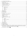
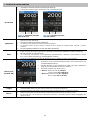
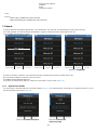
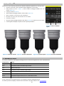
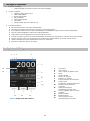
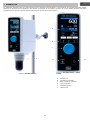
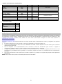
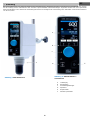
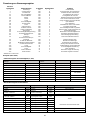
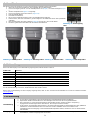
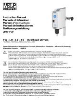
1. Introduction
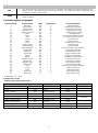
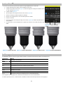
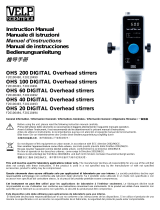
OHS overhead stirrers with electronic speed control, brushless motor, and advanced safety features are able to satisfy the most difficult
laboratory applications in terms of viscosity and volume. The new chuck ensures higher safety for the operator and allows to use a
passing rod of up to 8,5mm in diameter.
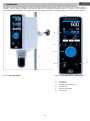
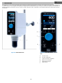
A
Display LCD
B
Display keys
C
Speed control knob
D
Lock key
E
Main switch
F
Smart Chuck
EN
Figure 1. OHS 200 Advance
F
Figura 1. OHS 200 Advance – Frontal
view
D
E
A
B
C

7
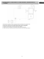
2. Assembly and installation
• Unpacking
➢ Check the integrity of the unit after unpacking.
• The box includes
➢ OHS advance overhead stirrer
➢ Power supply cable
➢ Instruction manual
➢ Allen key
➢ Allen head screw
➢ Shaft support overhead stirrer
➢ Pt100 probe Ø 3mm with cable
• First installation
➢ Place the unit on non-flammable surface
➢ Fix the shaft support to the instrument with the allen head screw
➢ Fasten the unit to the support rod (A00000366 or A00000369) using the double clamp (A00001301)
➢ Secure the receptacle using the ribbon clamp (A00001302)
➢ Slide the stirring rod into the chuck and tight it
➢ Make sure that the rating value of the instrument corresponds to the one of the power supply
➢ Ensure that the socket provided, with grounding, is compliant with the current safety norms and easy to reach. Use only
the cable provided with the instrument.
➢ Insert the power cable into the socket.
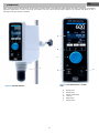
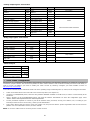
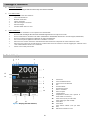
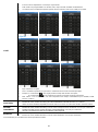
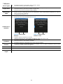
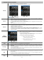
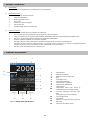
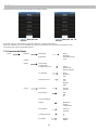
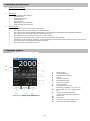
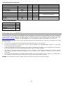
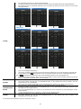
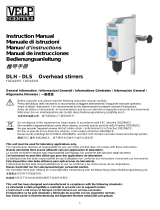
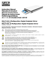
3. Display symbols
1
Wi-Fi symbol
2
Start Mode symbol
3
Vibration Sensor symbol
4
Hour
5
Current Speed
6
Set Speed
7
Timer or Time counter
8
Set Timer
9
Current Torque
10
Current temperature (only when
Pt100 probe is connected to OHS)
11
Gear button (only for OHS 200)
Graph button (for other models)
12
Timer button
13
Menu button
14
Current Gear symbol (only for OHS
200)
15
Current Method indication
5
6
7
1 2 3 4
4
8
9
10
13 12
11
14
15
Figure 3. Display (OHS 200 Advance)

8
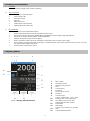
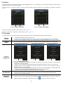
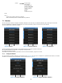
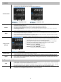
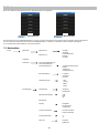
4. Working
Commissioning
➢ Switch on the instrument using the main switch (E)
➢ Display (A) shows Welcome page and the main screen
Stirring
➢ Adjust speed set point by turning the speed control knob (C). As soon as the knob is moved, set rpm (6)
becomes blue.
➢ Click the speed control knob (C) to start stirring.
➢ Speed increases until set point is achieved.
➢ A microprocessor ensures constant speed even when the viscosity changes (counter-reaction).
➢ Switch off the stirring by clicking the knob (C).
Timer
➢ Click Timer button (12) to select the timer.
➢ Set timer (8) time becomes blue. Adjust timer by turning the speed control knob (C).
➢ Click the knob (C) to confirm.
➢ If the instrument is already working, timer countdown starts immediately, otherwise timer (7) is fixed as set
timer (8) until stirring begins.
➢ If timer is not set, set timer (8) shows hh:mm:ss and timer (7) works as a counter.
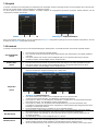
Gear (only for
OHS 200)
➢ Set the operating speed range by clicking Gear button (11) and
rotating the speed control knob (C).
➢ Click the knob (C) to confirm the speed range. Once confirmed,
Current Gear symbol becomes black.
➢ It’s possible to select between two gears:
➢ Gear I: Low speed (6 – 400 rpm)
High torque (till 200 Ncm).
➢ Gear II: High speed (30 – 2000 rpm)
Low torque (till 40 Ncm).
Torque
➢ The intensity of the torque is indicated on the main screen (9).
Lock
➢ Holding the Lock key (D) for 3 seconds, the instrument will lock its settings during operations.
➢ Unlock the control panel by holding the Lock key (D) for 3 seconds.
➢ If other buttons are clicked while the instrument is locked, the two LEDs aside lock button blink for many
seconds.
Figure 4. Main OHS 60 Advance
Figure 5. Main OHS 200 Advance
Figure 6. Set Gear

9
5. External Connections
USB
➢ Each model has USB connection in the back for PC controlling, data logging and software upgrading by PC.
➢ Software version, dedicated program to be installed in the PC, and software installation guide have to be
requested by e-mail to [email protected]
Pt100
➢ All models have Pt100 connection in the back for fluid temperature measurement (measuring range from -
200°C to +550°C)
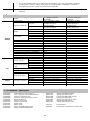
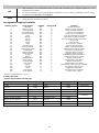
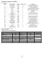
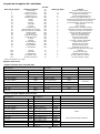
Controller register assignment
Register address
Register name
Write
Byte Number
Function/expanation
1
Instrument
NO
2
Instrument model
2
Serial number
NO
6
Instrument serial number
5
Product code
NO
12
Instrument product code
11
Main board sw
NO
8
Main board sw version
15
Display board sw
NO
8
Display board sw version
24
State
NO
2
Instrument state
25
Alarm
NO
2
The instrument notifies an alarm
26
Gear
NO
2
Gear set (only for OHS200)
27
Speed
NO
2
rpm measured
28
Torque
NO
2
Ncm measured
29
Timer
NO
4
Residual timer or counter
31
Timer set point
NO
4
Timer set value
33
Speed set point
NO
2
Speed set value
48
Pt100 connection
NO
2
Pt100 connected to the instrument
49
Temperature
NO
2
Temperature indication
50
Speed limit
NO
2
Speed maximum value
51
Torque limit
NO
2
Torque maximum value
52
Ramp
NO
2
Setting of acceleration
53
Method
NO
2
Reading of method number
54
Method n steps
NO
2
Total number of steps
55
Method step
NO
2
Current step visualized
56
Method n loops
NO
2
Total number of loops
57
Method loop
NO
2
Current loop visualized
102
Gear
SI
2
Setting of gear (only for OHS200)
103
Speed
SI
2
Setting of the speed
104
Timer
SI
4
Setting of the timer
106
Motor stop
SI
2
Motor stops stirring
107
Motor start
SI
2
Motor starts stirring
Sampling time: 1s or more
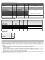
Examples (CRC 16 bit)
Reading single register: Speed (rpm)
Request
Reply
Field
(Hex)
Field
(Hex)
Description
Address
0x64
Address
0x64
Control command
0x03
Control command
0x03
High start address
0x00
Number of bytes
0x02
Low start address
0x1B
High register value
0x01
340 (RPM)
Number of High registers
0x00
Low register value
0x54
Number of Low registers
0x01
High CRC
0xF4
High CRC
0xFD
Low CRC
0x23
Low CRC
0xF8

10
Reading multiple register: Serial number
Request
Reply
Field
(Hex)
Field
(Hex)
Description
Address
0x64
Address
0x64
Control command
0x03
Control command
0x03
High start address
0x00
Number of bytes
0x06
Low start address
0x02
High register value
0x31
12345
Number of High registers
0x00
Low register value
0x00
Number of Low registers
0x03
High register value
0x33
High CRC
0xAD
Low register value
0x32
0x00 0x31 0x32 0x33 0x34 0x35
Low CRC
0xFE
High register value
0x35
Low register value
0x34
High CRC
0x0A
Low CRC
0x0A
Writing single register: STOP rotation
Request
Field
(Hex)
Description
Address
0x64
Control command
0x06
High start address
0x00
Low start address
0x6A
High register value
0x00
Stop rotation
Low register value
0x01
High CRC
0x61
Low CRC
0xE3
Virtual serial port
Baudrate
9600
Bits
8
Stop Bit
1
Patiry
None
Maximum number of
registers for single request
24
6. VELP Ermes Configuration
VELP Ermes is a revolutionary cloud platform that transforms and improves your laboratory experience by creating an ecosystem of
instruments, people and data. The VELP Ermes platform is able to reduce distances and accelerate scientific processes in total safety. In
order to access on ERMES, you need to enable your VELP account by selecting "Configure your VELP ERMES account" at
http://www.velp.com/en/login.
To be able to communicate, the instrument needs to be in the operating range of laboratory Wi-Fi (2.4 GHz) and be configured as follows:
➢ Switch on the OHS Advance and select AP in the menu Set-up Wi-Fi (see chapter 7.5).
➢ Using the PC/Tablet/Mobile phone, select the OHS_SERIAL NUMBER available on the Wi-Fi list, in order to connect directly to the
instrument.
➢ Open a browser on the PC/Tablet/Mobile phone and insert the address 192.168.240.1 to reach the configuration page. Insert
“admin” “admin” when requested as user name and password.
➢ Set the parameters required to connect to your Wi-Fi (network name, password, security, mac address, etc.) according to your
internal procedure and save. If necessary, contact your IT administrator.
➢ Select menu Ermes from the Service menu (see chapter 7.6) and proceed with the product registration from the VELP Ermes
platform. For more information see FAQ on VELP website.
NOTE: To access to VELP Ermes is necessary to have a VELP account.

11
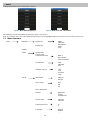
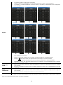
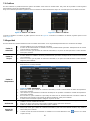
7. Menu
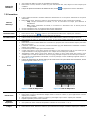
Clicking Menu button (13) the following figure appears
It’s possible to move among submenus rotating the speed control knob (C).
Enter in a submenu with a click of the speed control knob (C) once it’s highlighted in blue. Press Home to go back to the main screen.
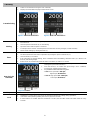
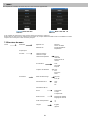
7.1 Menu Structure
Menu
Methods
Method 01
Steps
…
Start time
Method 10
Intermittent
mode
Loop
Graph**
Safety
Speed Limit
Torque Limit
Temperature Limit
Delta T
Interval time
Speed reduction
Acceleration
Slow
Standard
Fast
Vibration Sensor
OFF
Low
Medium
High
Set-up
Start Mode
Stop (A)
Run (B)
Wi-Fi Setup
OFF
ON
AP
Wi-Fi Information
Display
Brightness
Torque
Temperature
Time & Date
Set Time
Set Date
Temperature Unit
°C
°F
Language
English
Italiano
….
Figure 8. Menu OHS 100 - 60 Advance
Figure 7. Menu OHS 200 Advance

12
* Graph for models OHS 100 and OHS 60
** Not visualized for models OHS 100 and OHS 60
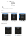
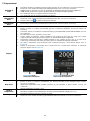
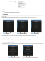
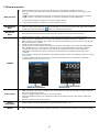
7.2 Methods
In this submenu is possible to set 10 different methods. For OHS 200, 10 different methods for each speed range.
Once set, a method becomes white in the method list and a blue bar appears on the left.
Press START to begin the method.
When a method is working, on the main screen the current method (15) is shown.
It’s not possible to modify speed, gear, or the timer.
It’s possible to navigate in menu.
To stop a method before its end, enter in the method list and click STOP.
7.2.1 Method set-up
In each method it’s possible to set parameters in Figure 12. Once method parameters are set, they are highlighted in white with a blue bar
on the left as shown in Figure 13.
Service
Reset Torque
Real Torque
Pt100 Alignment
Check Locking Ring
Reset Parameters
Update Software
Counter
Ermes
Motor Calibration
Timer
Gear *
Figure 9. Methods
Figure 2. Methods set
Figure 11. Stop Method
Figure 3. Method parameters
Figure 4. Method parameters set

13
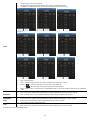
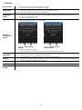
Steps
➢ 5 steps can be set for each method.
➢ All steps are programmable with speed, timer, ramp, and intermittent mode.
➢ A method is considered set when at least speed and timer are set for one step.
Figure 5
➢ Rpm: set point speed
➢ Time: countdown performed for each step visualized also on the main screen
➢ Ramp: if is selected, OHS stirs for all the time at the speed set
If is selected, OHS reaches the speed set in time selected
➢ Interm. Mode: if YES is selected, but no intermittent mode is set for the method, OHS works in continuous
mode.
Start Time
➢ It allows to set an hour at which the method starts.
➢ Enter in the menu, rotate speed control knob (C) till the desired hour. Click the knob to confirm.
➢ Even if a Start Time is set, the method begins if START button in method list is clicked.
Intermittent
Mode
➢ It allows to set stirring period and stop period alternatively.
➢ Enter in the menu, rotate speed control knob (C) till the desired working time. Click to confirm.
➢ Rotate speed control knob (C) till the desired pause time. Click to confirm.
➢ Click again the knob to modify set values.
Loop
➢ It allows to repeat the whole method N times.
➢ Enter in the menu, rotate speed control knob (C) till the desired value. Click to confirm.
Click RESET to erase all method values.

14
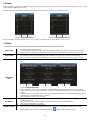
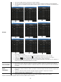
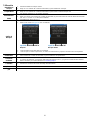
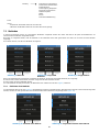
7.3 Graph
In this submenu is possible to visualize the graph of the current analysis. For models OHS 100 and OHS 60 is possible to access to the
graph directly through the main screen.
Click RESET to erase the graph. Only the last 60 minutes are shown. Click ZOOM to see the last 3 minutes.
When a method is set graph appears as in Figure 15. When a method is not set, graph appears as in Figure 16.
7.4 Safety
In this submenu it’s possible to set all limits linked to the safety depending on the working conditions
Speed Limit
➢ It allows to set the speed full scale.
➢ The maximum speed value is set by default (for OHS 200 it depends on the gear selected at the moment).
➢ Enter in the menu, rotate speed control knob (C) by 100 rpm steps till the desired value. Click to confirm.
Torque Limit
➢ It allows to set the torque limit.
➢ The maximum value is set by default (for OHS 200 it depends on the gear selected at the moment).
➢ Enter in the menu, rotate speed control knob (C) by 10 Ncm steps till the desired value. Click to confirm.
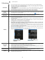
Temperature
Limit
➢ It allows to set a speed reduction if Pt100 detects a certain temperature increase (or decrease) in a defined
time.
Figure 8. Temperature Limit
➢ Enter in the menu, rotate speed control knob (C) till the delta temperature desired value. Click to confirm.
➢ Rotate the knob (C) to set the interval time in which the delta temperature has to be considered. Click to
confirm.
➢ Rotate the knob (C) to set the percentage of speed reduction desired if the selected delta temperature is
detected in the set interval time. Click to confirm.
➢ Speed reduction can be set by 10% steps.
Acceleration
➢ It allows to choose among 3 different acceleration types when the instrument starts to stir or when a higher
set point value is set.
➢ Enter in the menu, select Slow, Medium, or Fast depending on the customer application.
➢ Click speed control knob (C) to confirm.
Vibration sensor
➢ It allows to set a vibration sensitivity level.
➢ Enter in the menu, rotate speed control knob (C) to select OFF, Low, Medium or High. Click to confirm.
➢ When vibration sensor level is set different than OFF, appears on the blue upper bar (3).
Figure 6. Graph with method
Figure 7. Graph without method

15
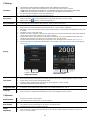
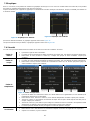
7.5 Set-up
Start Mode
➢ The decision of the instrument’s restart mode in case of blackout or power loss.
➢ Enter in the menu, rotate speed control knob (C) to select Stop or Run. Click to confirm.
➢ Stop: when the instrument is switched on, it’s requested a click of the control knob to start stirring.
➢ Run: when the instrument is switched on, it restarts to work with the last set point set.
➢ If Stop is selected, A appears on the blue upper bar (2).
➢ If Run is selected, B appears on the blue upper bar (2).
Wi-Fi Set-up
➢ It allows to switch on wi-fi module for IoT transmission.
➢ Enter in the menu, rotate speed control knob (C) to select ON or OFF. Click to confirm.
➢ When wi-fi is ON, appears on the blue upper bar (1).
Wi-Fi Information
➢ It describes all wi-fi information (MAC address, Power of signal, wi-fi name).
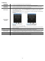
Display
➢ It allows for brightness to be set or if torque and temperature should be displayed on the main screen.
➢ Enter in the menu and scroll with speed control knob (C). Click to enter in submenus.
➢ Brightness: enter in this submenu, rotate speed control knob (C) to select the desired brightness value. Click
to confirm.
➢ Brightness can be set by 10% steps.
➢ Torque: enter in this submenu, rotate speed control knob (C) to choose between ON or OFF if the display of
torque on the main screen is desired or not. Click to confirm.
➢ Temperature: enter in this submenu, rotate speed control knob (C) to choose between ON or OFF if the
display of temperature on the main screen is desired or not. Click to confirm
➢ If torque and temperature are displayed on the main screen, the display menu appears as in Figure 18.
➢ When temperature is displayed but Pt100 probe is not inserted in the instrument, the main screen appears
as in Figure 19.
.
Time & Date
➢ It allows to set hour and date.
➢ Enter in the menu and select Set Time. Rotate speed control knob (C) till the right time. Click to confirm.
➢ Return to the previous page clicking BACK button.
➢ Select Set Date. Rotate speed control knob (C) till the right day. Click to confirm
➢ Repeat the operation for month and year.
Temperature Unit
➢ It allows to choose temperature unit that has to be visualized between °C and °F.
Language
➢ It allows to select the interface language.
➢ Enter in the menu, rotate speed control knob (C) to select language. Click to confirm.
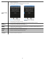
7.6 Service
Reset Torque
➢ It allows to reset the current torque.
➢ Click with the speed control knob (C) to reset torque.
Real Torque
➢ It allows to return to real torque value.
➢ Click with the speed control knob (C) to return to real torque value.
➢ Negative torques can’t be visualized anymore.
Pt100
Alignment
➢ It allows for the alignment of the Pt100 probe to a reference thermometer.
➢ Enter in the menu, rotate speed control knob (C) to select the desired alignment value (from -10.0°C to
10.0°C). Click to confirm.
Figure 9. Torque and
temperature shown
Figure 10. Main without
temperature probe

16
➢ Alignment sensitivity 0.1°C.
Check Locking
Ring
➢ It allows to control the right functioning of Smart Chuck system.
➢ Enter in the menu. Figure 20 is visualized.
➢ Follow instructions described in the screen.
➢ Once the operation is performed, Check becomes white and a blue bar appears on the left.
Reset
Parameters
➢ It allows to return to default value for all functions.
➢ Click with the speed control knob (C) to reset parameters.
Update
Software
➢ It allows to update the device with a new software version.
➢ Software version, dedicated program to be installed in the PC, and software installation guide have to be
requested by e-mail to [email protected].
Counter
➢ It allows to see the number of instrument working hours.
Ermes
➢ It allows to connect the instrument to Ermes Cloud.
Motor
Calibration
➢ It allows to reset the zero torque value.
Figure 11. Check Locking Ring
performed
Figure 12. Check Locking Ring

17
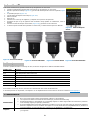
8. SmartChuckTM
This new mechanism (F) allows to change the stirring shaft with one hand.
➢ When instrument is off, hold the stirring shaft with one hand.
➢ From work position (Figure ), turn Locking Ring 90° to the left (Figure ).
➢ The main screen displays Figure 22.
➢ Pull Locking Ring down (Figure 25).
➢ Open the chuck.
➢ Remove the shaft.
➢ Introduce a new stirring shaft and place it in the operating position.
➢ Ensure the stirring shaft is centered as best as possible. Then close the chuck.
➢ Push Locking Ring up (Figure 26) and turn it 90° to the right.
➢ The yellow upper bar on the display becomes blue and the OHS is ready to be used.
9. Error messages
When the display shows an error message, the stirring function stops automatically.
Error code
Cause
AL1
Motor doesn’t start stirring
AL2
High internal motor temperature
AL3
Motor overload
AL4
High driver temperature
AL5
Safety relay intervened
AL10
Vibrations too high
AL11
Temperature too high (only with Pt100 inserted)
AL12
Temperature too low (only with Pt100 inserted)
To remove the error message, disconnect the instrument from the power supply.
If alarm persists on the display, please contact VELP Scientifica’s technical service department. [email protected]
10. Maintenance
Maintenance
➢ No routine or extraordinary maintenance is necessary;
➢ Repairs must be carried out by authorized Velp personnel only;
➢ Instrument must be transported in its original packaging any indications present on the original packaging must
be followed (e.g. palletized);
Figure 13. Locking Ring open
Figure 23. Working position
Figure 24. Intermediate position
Figure 15. Open position
Figure 14. Intermediate position

18
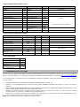
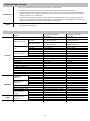
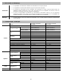
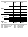
11. Technical data
Models
F20100480, F20100481,
F20100482
F20110480, F20110481,
F20110482
General
features
Power supply
230 V / 50-60 Hz (+/-10%)
115V / 60 Hz (+/-10%)
Dimensions (WxHxD)
OHS 200
90x315x235 mm
(3.54x12.40x9.25 in)
90x315x235 mm
(3.54x12.40x9.25 in)
OHS 100 – OHS 60
90x285x235 mm
(3.54x11.22x9.25 in)
90x285x235 mm
(3.54x11.22x9.25 in)
Weight
OHS 200
4,6 kg (10,14 lb)
4,6 kg (10,14 lb)
OHS 100
4,1 kg (9,04 lb)
4,1 kg (9,04 lb)
OHS 60
4,1 kg (9,04 lb)
4,1 kg (9,04 lb)
Power input
OHS 200
150 W
150 W
OHS 100
175 W
175 W
OHS 60
165 W
165 W
Construction material (structure)
Aluminum
Aluminum
Working in continuous
Admitted
Admitted
Settable restart modality
Stop or work
Stop or work
Noisiness
<< 60 dBa
<< 60 dBa
Environmental temperature admitted
+5…+40 °C
+5…+40 °C
Storage temperature admitted
-10…+60 °C
-10…+60 °C
Max humidity
80%
80%
Level of electrical protection CEI EN60529
IP 54
IP 54
Overvoltage category
II
II
Pollution degree CEI EN61010-1
2
2
Max altitude
2000 m
2000 m
Stir
Stirring capacity
OHS 200
100 l H2O
100 l H2O
OHS 100
100 l H2O
100 l H2O
OHS 60
40 l H2O
40 l H2O
Programmable speed
range
OHS 200
6-400rpm (I) – 30-2000rpm (II)
6-400rpm (I) – 30-2000rpm (II)
OHS 100
30-1300rpm
30-1300rpm
OHS 60
30-2000rpm
30-2000rpm
Motor type
BLDC
BLDC
Speed selection
1 rpm step
1 rpm step
Stirring alarm
Motor fault
Motor fault
Motor rating output
OHS 200
84 W
84 W
OHS 100
136 W
136 W
OHS 60
126 W
126 W
Torque
Max torque admitted
OHS200
200 Ncm (I) – 40 Ncm (II)
200 Ncm (I) – 40 Ncm (II)
OHS100
100 Ncm
100 Ncm
OHS60
60 Ncm
60 Ncm
Counters
Motor counter
Working hours
Working hours
12. Accessories / Spare parts
A00000002 Probe extension cable, length 1 m
A00000363 Glass Temperature Probe OHS Advance
A00000366 Support rod and base OHS
A00000369 Telescopic support rod and base OHS
A00000391 OHS/ControllerSoft
A00000372 Support rod for probe
A00001300 Support rod and base
A00001301 Double clamp
A00001302 Ribbon clamp
A00001304 Stirring shaft with floating blade
A00001305 Stirring shaft with folding blade
A00001306 Stirring shaft with fixed blade
A00001307 Stirring shaft with propeller
A00001308 Stirring shaft with paddle, 6 holes
A00001309 Stirring shaft with turbine
A00001310 Stirring shaft with turbo propeller
A00001311 Stirring shaft with anchor
A00001312 Stirring shaft protection OHS
10007175 Knob 35D blue
40002632 Pt100 probe Ø 3 OHS Advance with cable
➢ It is the responsibility of the user, to properly decontaminate the unit in case of hazardous substances
remaining on the surface or interior of the device. If in doubt about the compatibility of a cleaning or
decontamination product, contact the manufacturer or distributor.
Cleaning
➢ Disconnect the unit from the power supply and use a cloth dampened with a non-flammable non-aggressive
detergent.

19
1. Introduzione
Gli agitatori ad asta OHS sono dotati di un sistema di controllo elettronico della velocità, motore senza spazzole e un avanzato sistema di
sicurezza. Sono in grado di soddisfare le più svariate applicazioni di laboratorio in termini di volume e viscosità. Il nuovo sistema di
chiusura del mandrino garantisce una maggiore sicurezza all’operatore permettendo di utilizzare aste passanti fino a 8,5mm di diametro.
A
Display LCD
B
Tasti display
C
Encoder velocità agitazione
D
Tasto di blocco
E
Interruttore principale
F
Smart Chuck
D
E
A
B
C
IT
Figura 17. OHS 200 Advance
Figura 16. OHS 200 Advance – Vista frontale

20
2. Montaggio e installazione
• Rimozione dall’imballo
➢ Controllare l’integrità dello strumento dopo aver rimosso l’imballo
• La scatola include
➢ Agitatore ad asta OHS Advance
➢ Cavo di alimentazione
➢ Manuale di istruzioni
➢ Chiave esagonale
➢ Vite testa esagono incassato
➢ Asta di sostegno
➢ Sonda Pt100 Ø 3mm con cavo
• Prima installazione
➢ Posizionare lo strumento su una superficie non infiammabile.
➢ Fissare l’asta di sostegno allo strumento mediante l’apposita vite ad esagono incassato.
➢ Fissare saldamente lo strumento allo stativo (A00000366 o A00000369) utilizzando il morsetto doppio (A00001301).
➢ Fissare il recipiente di agitazione utilizzando la cinghia (A00001302).
➢ Far scorrere la pala di agitazione attraverso il mandrino e serrarla.
➢ Assicurarsi che il valore di tensione di alimentazione dello strumento corrisponda al valore di tensione di rete.
➢ Assicurarsi che la presa di corrente fornita sia conforme alle norme di sicurezza e facile da raggiungere. Utilizzare solo il
cavo di alimentazione fornito con lo strumento.
➢ Inserire il cavo nella presa di rete.
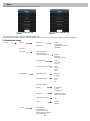
3. Simboli display
1
Icona Wi-Fi
2
Icona modalità di riavvio
3
Icona sensore di vibrazioni
4
Ora
5
Velocità attuale
6
Velocità di set point
7
Timer o contatore
8
Timer set point
9
Coppia attuale
10
Temperatura attuale (solo quando la
sonda Pt100 è connessa)
11
Tasto marcia (solo per OHS 200)
Tasto grafico (per altri modelli)
12
Tasto timer
13
Tasto Menu
14
Icona Marcia attuale (solo per OHS
200)
15
Indicazione metodo in corso
5
6
7
1 2 3 4
4
8
9
10
13 12
11
14
15
Figure 3. Display (OHS 200 Advance)
Seite wird geladen ...
Seite wird geladen ...
Seite wird geladen ...
Seite wird geladen ...
Seite wird geladen ...
Seite wird geladen ...
Seite wird geladen ...
Seite wird geladen ...
Seite wird geladen ...
Seite wird geladen ...
Seite wird geladen ...
Seite wird geladen ...
Seite wird geladen ...
Seite wird geladen ...
Seite wird geladen ...
Seite wird geladen ...
Seite wird geladen ...
Seite wird geladen ...
Seite wird geladen ...
Seite wird geladen ...
Seite wird geladen ...
Seite wird geladen ...
Seite wird geladen ...
Seite wird geladen ...
Seite wird geladen ...
Seite wird geladen ...
Seite wird geladen ...
Seite wird geladen ...
Seite wird geladen ...
Seite wird geladen ...
Seite wird geladen ...
Seite wird geladen ...
Seite wird geladen ...
Seite wird geladen ...
Seite wird geladen ...
Seite wird geladen ...
Seite wird geladen ...
Seite wird geladen ...
Seite wird geladen ...
Seite wird geladen ...
Seite wird geladen ...
Seite wird geladen ...
Seite wird geladen ...
Seite wird geladen ...
Seite wird geladen ...
Seite wird geladen ...
Seite wird geladen ...
Seite wird geladen ...
Seite wird geladen ...
Seite wird geladen ...
Seite wird geladen ...
Seite wird geladen ...
Seite wird geladen ...
Seite wird geladen ...
Seite wird geladen ...
Seite wird geladen ...
-
 1
1
-
 2
2
-
 3
3
-
 4
4
-
 5
5
-
 6
6
-
 7
7
-
 8
8
-
 9
9
-
 10
10
-
 11
11
-
 12
12
-
 13
13
-
 14
14
-
 15
15
-
 16
16
-
 17
17
-
 18
18
-
 19
19
-
 20
20
-
 21
21
-
 22
22
-
 23
23
-
 24
24
-
 25
25
-
 26
26
-
 27
27
-
 28
28
-
 29
29
-
 30
30
-
 31
31
-
 32
32
-
 33
33
-
 34
34
-
 35
35
-
 36
36
-
 37
37
-
 38
38
-
 39
39
-
 40
40
-
 41
41
-
 42
42
-
 43
43
-
 44
44
-
 45
45
-
 46
46
-
 47
47
-
 48
48
-
 49
49
-
 50
50
-
 51
51
-
 52
52
-
 53
53
-
 54
54
-
 55
55
-
 56
56
-
 57
57
-
 58
58
-
 59
59
-
 60
60
-
 61
61
-
 62
62
-
 63
63
-
 64
64
-
 65
65
-
 66
66
-
 67
67
-
 68
68
-
 69
69
-
 70
70
-
 71
71
-
 72
72
-
 73
73
-
 74
74
-
 75
75
-
 76
76


Velp Scientifica OHS Advanvce Benutzerhandbuch
- Typ
- Benutzerhandbuch
in anderen Sprachen
Verwandte Artikel
-
 Velp Scientifica OHS Digital Benutzerhandbuch
-
 Velp Scientifica ECO 6 Benutzerhandbuch
-
Velp Scientifica CG-1995-V-20 Bedienungsanleitung
-
 Velp Scientifica BOD Sensor Benutzerhandbuch
-
 VELP Scientific VLP-SB20510465 Bedienungsanleitung
-
 Velp Scientifica RESPIROMETRIC Sensor Benutzerhandbuch
-
 Velp Scientifica DLS DLH Benutzerhandbuch
-
 Velp Scientifica PW-LH-LS-ES Benutzerhandbuch
-
 VELP Scientific F20510530 Bedienungsanleitung


