Audiotec Fischer MATCH UP 1FX Bedienungsanleitung
- Kategorie
- Musikausrüstung
- Typ
- Bedienungsanleitung

UP 1FX
UPGRADE
1-Kanal Upgrade-Subwoofer-Verstärker mit
integrierter Frequenzweiche und 1 Ohm Stabilität
1-channel upgrade subwoofer amplier with
integrated crossover and 1 Ohm stability
deutsch / english

2
Sehr geehrter Kunde,
wir gratulieren Ihnen zum Kauf dieses hochwertigen
MATCH Verstärkers.
Audiotec Fischer setzt mit der UP 1FX neue
Maßstäbe im Bereich der Verstärkertechnik.
Dabei protieren Sie als Kunde direkt von unserer
mehr als 30-jährigen Erfahrung in der Forschung
und Entwicklung von Audiokomponenten.
Dieser Upgrade-Verstärker wurde von uns nach
neuesten technischen Erkenntnissen entwickelt und
zeichnet sich durch hervorragende Verarbeitung
und eine überzeugende Anwendung ausgereifter
Technologien aus.
Viel Freude an diesem Produkt wünscht Ihnen das
Team von
AUDIOTEC FISCHER
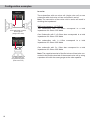
Allgemeines zum Einbau von MATCH-Kompo-
nenten
Um alle Möglichkeiten des Produktes optimal aus-
schöpfen zu können, lesen Sie bitte sorgfältig die
nachfolgenden Installationshinweise. Wir garantie-
ren, dass jedes Gerät vor Versand auf seinen ein-
wandfreien Zustand überprüft wurde.
Vor Beginn der Installation unterbrechen Sie
den Minusanschluss der Autobatterie.
Wir empfehlen Ihnen, die Installation von einem
Einbauspezialisten vornehmen zu lassen, da der
Nachweis eines fachgerechten Einbaus und An-
schlusses des Gerätes Voraussetzung für die Ga-
rantieleistungen sind.
Installieren Sie Ihren Verstärker an einer trockenen
Stelle im Auto und vergewissern Sie sich, dass
der Verstärker am Montageort genügend Kühlung
erhält. Montieren Sie das Gerät nicht in zu kleine,
abgeschlossene Gehäuse ohne Luftzirkulation oder
in der Nähe von wärmeabstrahlenden Teilen oder
elektronischen Steuerungen des Fahrzeuges.
Im Sinne der Unfallsicherheit muss der Verstär-
ker professionell befestigt werden. Verwenden
Sie hierzu die zwei im Lieferumfang enthaltenen
Montagebleche. Diese werden mit jeweils zwei
kurzen Schrauben (im Lieferumfang enthalten) an
der Unterseite des Verstärkers befestigt. Wenn Sie
den Verstärker mittels Schrauben an der Karosse-
rie befestigen, so vergewissern Sie sich, dass die
Montageäche genügend Halt bietet und keine
elektrischen Kabel und Komponenten, hydraulische
Bremsleitungen, der Benzintank etc. dahinter ver-
borgen sind. Diese könnten sonst beschädigt wer-
den. Achten Sie bitte darauf, dass sich solche Teile
auch in der doppelten Wandverkleidung verbergen
können.
Allgemeines zum Anschluss des UP 1FX
Verstärkers
Der Verstärker darf nur in Kraftfahrzeuge eingebaut
werden, die den 12 V-Minuspol an Masse haben.
Bei anderen Systemen können der MATCH Verstär-
ker und die elektrische Anlage des Kfz beschädigt
werden. Die Plusleitung für die gesamte Anlage
sollte in einem Abstand von max. 30 cm von der
Batterie mit einer Hauptsicherung abgesichert wer-
den. Der Wert der Sicherung errechnet sich aus der
maximalen Stromaufnahme der Car-Hi Anlage.
Verwenden Sie zum Anschluss des Verstärkers
an die Stromversorgung des Fahrzeugs aus-
schließlich geeignete Kabel mit ausreichendem
Kabelquerschnitt. Die Sicherungen im Verstär-
ker dürfen nur mit den gleichen Werten (2 x
30 A) ersetzt werden, um eine Beschädigung
des Gerätes zu verhindern. Höhere Werte kön-
nen zu gefährlichen Folgeschäden führen!
Die Kabelverbindungen müssen so verlegt sein,
dass keine Klemm-, Quetsch- oder Bruchgefahr be-
steht. Bei scharfen Kanten (Blechdurchführungen)
müssen alle Kabel gegen Durchscheuern gepols-
tert sein. Ferner darf das Versorgungskabel niemals
mit Zuleitungen zu Vorrichtungen des Kfz (Lüfter-
motoren, Brandkontrollmodulen, Benzinleitungen
etc.) verlegt werden.
Herzlichen Glückwunsch!
Allgemeine Hinweise

3
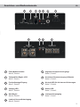
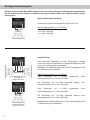
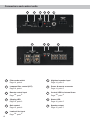
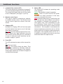
deAnschluss- und Bedienelemente
1 2 3 4 5
1 Filter-Modus-Schalter
Seite 5, Punkt 4
2 Tiefpasslter-Regler (LPF)
Seite 7, Punkt 1
3 Fernbedienungs-Eingang
Seite 7, Punkt 2
4 Clipping LED
Seite 7, Punkt 3
5 Gain-Regler
Seite 6, Punkt 6
6 Lowlevel-Vorverstärkereingang
Seite 5, Punkt 2
7 Highlevel-Lautsprechereingänge
Seite 5, Punkt 3
8 Anschluss Stromversorgung & Remote
Seite 5, Punkt 5
9 Kontroll LED für die internen Sicherungen
Seite 7, Punkt 4
10 Status LED
Seite 7, Punkt 5
11 Lautsprecherausgang
Seite 7, Punkt 7
8 9 10 11
6 7

4
Kongurieren Sie den MATCH UP 1FX Verstär-
ker in der nachfolgenden Reihenfolge
Achtung: Für die Durchführung der nachfolgenden
Schritte werden Spezialwerkzeuge und Fachwissen
benötigt. Um Anschlussfehler und Beschädigungen
zu vermeiden, fragen Sie im Zweifelsfall Ihren Ein-
bauspezialisten und beachten Sie zwingend die
allgemeinen Anschluss- und Einbauhinweise (siehe
Seite 2).
1. Einstellung des Eingangsspannungsbe-
reichs
Bevor Sie beginnen, den Eingangsspannungs-
bereich („Voltage Range“) der Signaleingänge
anzupassen, beachten Sie bitte die folgenden
Hinweise. Diese Einstellung ist nur erforderlich,
wenn Sie Geräte aus den folgenden Kategorien
anschließen:
- Aftermarket-Radios mit mehr als 3 V RMS
Ausgangsspannung
- Premium Soundsystem-Verstärker mit
mehr als 50 W RMS Ausgangsleistung
- Stand-Alone DSPs mit mehr als 3 V RMS
Ausgangsspannung
Für Standardanwendungen wie den Anschluss
von:
- Audiotec Fischer DSP-Verstärkern über
Cinch-Kabel
- Original-Radios
- Aftermarket-Radios mit weniger als 3 V
RMS Ausgangsspannung
ist diese Einstellung nicht erforderlich. In die-
sem Fall können Sie direkt auf Seite 5 mit
Punkt 2 fortfahren.
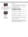
So stellen Sie den Eingangsspannungsbe-
reich ein:
a. Verstärker önen
Entfernen Sie das Seitenblech mit dem
Fernbedienungseingang, indem Sie die drei
Inbusschrauben lösen und das Bodenblech
zur Seite herausziehen.
b. Ausgangsspannung der Signalquelle er-
mitteln
Wir empfehlen, die maximale Ausgangs-
spannung mithilfe eines geeigneten Mess-
geräts zu ermitteln oder sich an Ihren auto-
risierten MATCH Fachhändler zu wenden.
Wenn Sie unsicher sind, empfehlen wir, den
Jumper auf den „High Voltage Range“ (Cinch
1 - 6 V / Highlevel 6 - 32 V) einzustellen, um
mögliche Schäden am Gerät zu vermeiden.
Hierfür muss der Jumper auf die werkseitig
unbenutzte Stiftleiste umgesteckt werden,
wie in Abbildung 2 gezeigt.
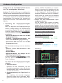
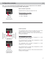
c. Jumper auf den entsprechenden Span-
nungsbereich setzen
Um die Position des Jumpers zu ändern,
ziehen Sie ihn einfach nach oben ab und
stecken Sie ihn in die gewünschte Position.
Achten Sie darauf, dass der Jumper vollstän-
dig und ohne Versatz eingesteckt ist.
Übersicht Jumper-Steckpositionen:
Low Voltage Range Konguration
( werkseitig / siehe Abb. 1):
Wertebereich: HLI (Highlevel) 3 - 16 Volt
RCA (Cinch) 0,5 - 3 Volt
High Voltage Range Konguration
(siehe Abb.2):
Wertebereich: HLI (Highlevel) 6 - 32 Volt
RCA (Cinch) 1 - 6 Volt
Abbildung 1:
Abbildung 2:
d. Verstärker wieder zusammenbauen
Hardware-Konguration

5
de
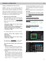
2. Anschluss des Lowlevel-Vorverstärkerein-
gangs
Der Vorverstärkereingang (Line Input) kann mit
einem entsprechenden Kabel an den RCA /
Cinch-Ausgang der Signalquelle (bspw. Radio /
DSP / DSP-Verstärker) angeschlossen werden.
Die Eingangsempndlichkeit kann mit Hilfe des
Gain-Reglers optimal an die Signalquelle ange-
passt werden (siehe Seite 6, Punkt 6).
Hinweis: Eine gleichzeitige Verwendung des
Vorverstärkereingangs und den Hochpegel-
Lautsprechereingängen ist nicht möglich und
kann zu Schäden an der Signalquelle führen.
3. Anschluss der Highlevel-Lautsprecherein-
gänge
Die Hochpegel-Lautsprechereingänge A und B
(High level Input) können direkt mit den Laut-
sprecherausgängen der Signalquelle (bspw.
Radio / DSP / DSP-Verstärker) mit Hilfe ent-
sprechender Kabel (Lautsprecherkabel mit
max. 1 mm² Querschnitt) verbunden werden.
Achten Sie bitte auf eine korrekte Polung!
Wenn Sie einen Anschluss verpolen, kann da-
durch die Funktion des Verstärkers beeinträch-
tigt werden. Der Highlevel-Eingang verfügt über
den ADEP.3-Schaltkreis (Advanced Diagnostics
Error Protection der 3 Generation), der dafür
sorgt, dass der Verstärker auch von OEM Ra-
dios als Lautsprecher erkannt wird und somit im
Werksradio keine Funktionen deaktiviert wer-
den und auch kein Eintrag im Fehlerspeicher
des Fahrzeugs erzeugt wird. Bei Verwendung
dieses Eingangs schaltet der Verstärker bei
allen handelsüblichen Radios automatisch ein,
so dass dieser nicht über den Remote-Eingang
(REM) eingeschaltet werden muss.
Achtung: Verwenden Sie zum Anschluss aus-
schließlich den mitgelieferten Stecker mit integ-
rierten Schraubklemmen.
Achtung: Eine gleichzeitige Verwendung des
Vorverstärkereingangs und den Hochpegel-
Lautsprechereingängen ist nicht möglich und
kann zu Schäden an der Signalquelle führen.
4. Einstellen des Filter-Modus der internen
Frequenzweiche
Die UP 1FX ist mit einer DirectDSP Funktion
ausgestattet. Diese ermöglicht es, die interne
Frequenzweiche zu umgehen. Mit Hilfe des
X-Over-Schalters (Seite 3, Punkt 1) kann die
Funktion aktiviert bzw. deaktiviert werden.
DirectDSP: Die interne Frequenzweiche ist
nicht aktiv und das Eingangssignal wird unge-
ltert an die Endstufe gegeben.
Bandpass: Bei dieser Schalterstellung ist die
interne Frequenzweiche zugeschaltet und ein
15 Hz Hochpasslter (Subsonic) immer aktiv.
Das heißt, es wird ein Bandpass gebildet. Mit
dem Tiefpasslter-Regler (LPF, Seite 3, Punkt
2) kann dieser beliebig zwischen 50 Hz und 250
Hz eingestellt werden.
5. Anschluss der Stromversorgung & Remote
Vor dem Anschluss des +12 V
Versorgungskabels an das Bordnetz muss
die Autobatterie abgeklemmt werden.
Achten Sie unbedingt auf eine korrekte Polari-
tät.
+12 V: Anschluss für die Plusleitung.
Das +12 V Stromkabel ist am Pluspol der Bat-
terie anzuschließen. Die Plusleitung sollte in
einem Abstand von max. 30 cm von der Batterie
mit einer Hauptsicherung abgesichert werden.
Der Wert der Sicherung errechnet sich aus der
maximalen Stromaufnahme der gesamten Car-
Hi Anlage (UP 1FX = max. 60 A RMS bei 12 V
Bordnetz). Verwenden Sie bei kurzen Leitungen
(< 1 m) einen Querschnitt von mindestens
16 mm². Bei längeren Leitungen empfehlen wir
einen Querschnitt von 25 mm² bis 35 mm².
GND: Anschluss für die Masseleitung. Das Mas-
sekabel muss an einer nicht isolierten Stelle mit
dem Kfz-Chassis oder direkt mit dem Minuspol
der Autobatterie verbunden werden. Der Kabel-
querschnitt sollte den gleichen Durchmesser
wie die Plusleitung haben. Ein nicht ausrei-
chender Massekontakt führt zu unerwünschten
Störgeräuschen und Fehlfunktionen.

6
REM: Der Remote-Eingang dient zum Ein- und
Ausschalten der UP 1FX. Dieser wird mit dem
Remote-Ausgang der unmittelbar vorgeschal-
teten Komponente, welche das Eingangssignal
für die UP 1FX liefert, verbunden. Der Eingang
muss nicht belegt werden, wenn der Highlevel-
Lautsprechereingang (Highlevel Input) benutzt
wird. Es wird dringend davon abgeraten, den
Remote-Eingang des Verstärkers über das
Zündungsplus des Fahrzeugs zu steuern, um
Störgeräusche beim Ein- und Ausschalten zu
vermeiden.
6. Einstellen der Eingangsempndlichkeit
ACHTUNG: Es ist zwingend notwendig,
die Eingangsempndlichkeit der UP 1FX an
die Signalquelle anzupassen, um eine best-
mögliche Signalqualität zu garantieren und
Schäden am Verstärker zu vermeiden. Au-
ßerdem ist es zuvor zwingend erforderlich
den Wertebereich (Voltage Range) an die
Ausgangsspannung Ihrer Signalquelle an-
zupassen (siehe Seite 4, Punkt 1).
Mit Hilfe des Gain-Reglers (Seite 3, Punkt 5)
kann die Eingangsempndlichkeit optimal an
die Signalquelle angepasst werden.
Dieser Regler ist kein Lautstärkeregler, sondern
dient nur der Anpassung. Die Einstellung des
Reglers beeinusst sowohl den Vorverstärke-
reingang als auch die Highlevel-Eingänge!
Werkseitig ist die Eingangsempndlichkeit auf
16 Volt (Highlevel) bzw. 3 Volt (Cinch) voreinge-
stellt. Dies ist in nahezu allen Fällen bereits die
optimale Einstellung.
Die Gain-Regelbereiche sind:
Low Voltage Range Konguration:
Highlevel: 3 - 16 Volt
Cinch: 0,5 - 3 Volt
High Voltage Range Konguration:
Highlevel: 6 - 32 Volt
Cinch: 1 - 6 Volt
Sollte die Signalquelle eine niedrigere Aus-
gangsspannung liefern, kann die Eingangs-
empndlichkeit über den Gain-Regler stufenlos
angehoben werden.
Sofern Ihre Signalquelle eine höhere Aus-
gangsspannung liefert, beispielsweise im Falle
eines vorgeschalteten OEM / Werksverstär-
kers, muss die Eingangsempndlichkeit über
den Regler zwingend abgesenkt werden und
die korrekte Konguration des „Voltage Range“
Jumpers überprüft werden.
Sollten Sie sich bzgl. der Ausgangsspannung
Ihrer Signalquelle nicht sicher sein, kontaktie-
ren Sie Ihren MATCH Fachhändler.
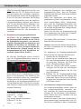
Die Clipping LED (siehe Seite 3, Punkt 4) dient
dabei als Kontrollinstrument.
Hinweis: Schließen Sie während dieser Proze-
dur keine Lautsprecher an die Ausgänge des
Verstärkers an.
Zur Anpassung der Eingangsempndlichkeit
führen Sie bitte die folgenden Schritte durch:
1. Schalten Sie den Verstärker ein.
2. Drehen Sie die Lautstärke Ihres Radios auf
90 % der Gesamtlautstärke und spielen Sie
ein geeignetes Testsignal, z.B. Rosa Rau-
schen, (Vollaussteuerung 0 dB) ab.
3. Sollte die Clipping LED bereits leuchten,
verringern Sie mit Hilfe des Gain-Reglers
die Eingangsempndlichkeit, bis die Clip-
ping LED erlischt.
4. Erhöhen Sie die Eingangsempndlichkeit
durch Rechtsdrehung bis die Clipping LED
aueuchtet. Drehen Sie nun den Gain-Reg-
ler gegen den Uhrzeigersinn bis die Clipping
LED wieder erlischt.
7. Anschluss der Lautsprecherausgänge
Die Lautsprecherausgänge können direkt mit
den Lautsprecherleitungen verbunden wer-
den. Verbinden Sie niemals die Lautsprecher-
leitungen mit der Kfz-Masse (Fahrzeugkaros-
serie). Dieses kann Ihren Verstärker und Ihre
Lautsprecher zerstören.
Achten Sie darauf, dass alle Lautsprechersy-
steme phasenrichtig angeschlossen sind, d.h.
Plus zu Plus und Minus zu Minus. Vertauschen
Hardware-Konguration

7
de
von Plus und Minus hat einen Totalverlust der
Basswiedergabe zur Folge. Der Pluspol ist bei
den meisten Lautsprechern gekennzeichnet.
Die Impedanz darf 1 Ohm nicht unterschreitenn,
da sonst die Schutzschaltung des Verstärkers
aktiviert wird. Beispiele für den Lautsprecher-
anschluss nden Sie auf Seite 8 .
8. Filtereinstellungen
Sofern Sie die DirectDSP-Funktion (siehe
Seite 5, Punkt 4) aktiviert haben, müssen die
Übernahmefrequenzen für den Subsonic bzw.
Tiefpass im vorgeschalteten DSP oder DSP-
Verstärker eingestellt werden.
Bei der Nutzung der Bandpassfunktion verwen-
den Sie den Tiefpasslter-Regler (LPF) am Ge-
rät. In diesem Fall ist ein 15 Hz Hochpasslter
(Subsonic) immer aktiv.
1. Tiefpasslter-Regler (LPF)
Mit Hilfe dieses Reglers kann das Tiefpasslter
des Bandpasses von 50 Hz bis 250 Hz einge-
stellt werden. Der Regler wird aktiviert, wenn
der X-Over Schalter auf „Bandpass“ eingestellt
ist (siehe Seite 5, Punkt 4).
2. Fernbedienungseingang
Eingang zum Anschluss einer optional erhält-
lichen Fernbedienung. Mit Hilfe dieser Fernbe-
dienung lässt sich die Lautstärke des Subwoo-
fers kontrollieren.
3. Clipping LED
In der Regel ist die LED aus und leuchtet nur
auf, wenn der Vorverstärker- oder einer der
Highlevel-Signaleingänge übersteuert wird.
An (rot): Einer der analogen Signaleingänge
wird übersteuert. Senken Sie die Eingangsemp-
ndlichkeit mit Hilfe des Gain-Reglers ab, bis
die LED erlischt. Wie Sie die Eingangsempnd-
lichkeit absenken, ist auf Seite 6 unter Punkt 6
nachzulesen.
4. Fuse LED
Die Fuse LED zeigt den Zustand der internen
Eingangssicherungen an.
Aus: Sicherungen intakt.
An (rot): Sicherungen defekt. Die Sicherungen
im Verstärker dürfen nur mit den gleichen Wer-
ten (2 x 30 A) ersetzt werden, um eine Beschä-
digung des Gerätes zu verhindern. Höhere
Werte können zu gefährlichen Folgeschäden
führen!
5. Status LED
Die Status LED zeigt den Betriebszustand des
Verstärkers und dessen Speichers an.
Grün: Verstärker eingeschaltet und betriebsbereit.
Orange: Protection Mode aktiv. Ein Kurzschluss
am Lautsprecherausgang oder Fehlanschluss
liegt vor. Prüfen Sie in diesem Fall alle An-
schlüsse auf Fehler.
Rot: Protection Mode aktiv. Dieser kann unter-
schiedliche Ursachen haben. Der Verstärker ist
mit Schutzschaltungen gegen Über- und Un-
terspannung sowie Überhitzung ausgestattet.
Prüfen Sie in diesem Fall alle Anschlüsse auf
Fehler, wie z.B. Kurzschlüsse oder fehlerhafte
Verbindungen. Ist die Sicherheitsschaltung der
Temperaturüberwachung aktiv, wird die Signal-
ausgabe abgeschaltet, bis ein sicherer Betrieb
wieder gewährleistet werden kann.
Sollte sich der Verstärker nach Beseitigung der
Fehlerquelle nicht wieder einschalten lassen,
liegt ein Defekt vor und er muss zur Reparatur
eingeschickt werden. Wenden Sie sich hierzu
an einen autorisierten MATCH Händler vor Ort.
Weitere Funktionen

8
Kongurationsbeispiele
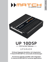
Mono-Subwooferanwendung
Subwoofer mit einer Schwingspule (Single Voice Coil)
RMS-Ausgangsleistung ≤ 1% THD+N:
1 x 4 Ohm: 350 Watt
1 x 2 Ohm: 600 Watt
1 x 1 Ohm: 900 Watt
Hinweis: Sofern Sie die DirectDSP-Funktion aktiviert haben, müssen Sie die Übernahmefrequenzen
für den Subsonic bzw. Tiefpass mit Hilfe eines vorgeschalteten DSPs oder DSP-Verstärkers einge-
stellt werden.
Parallelbetrieb
Zwei identische Subwoofer mit einer Schwingspule (Single
Voice Coil) oder ein Subwoofer mit Doppelschwingspule (Dual
Voice Coil) werden parallel geschaltet.
Hinweis: Die Parallelschaltung von zwei Schwingspulen führt
zur Halbierung der Impedanz!
RMS-Ausgangsleistung ≤ 1% THD+N:
Zwei Subwoofer mit 1 x 4 Ohm entsprechen einer
Gesamtimpedanz von 2 Ohm: 600 Watt
Ein Subwoofer mit 2 x 4 Ohm entspricht ebenso einer
Gesamtimpedanz von 2 Ohm: 600 Watt
Zwei Subwoofer mit 1 x 2 Ohm entsprechen einer
Gesamtimpedanz von 1 Ohm: 900 Watt
Ein Subwoofer mit 2 x 2 Ohm entspricht ebenso einer
Gesamtimpedanz von 1 Ohm: 900 Watt
Hinweis: Das Parallelschalten von 1 Ohm Schwingspulen führt
zu Abschaltung des Verstärkers.
Ein Subwoofer mit
Doppelschwingspule
(Dual Voice Coil)
Zwei Subwoofer mit einer
Schwingspule
(Single Voice Coil)

9
de
Ein Subwoofer mit
Doppelschwingspule
(Dual Voice Coil)
Zwei Subwoofer mit einer
Schwingspule
(Single Voice Coil)
Reihenbetrieb
Zwei identische Subwoofer mit einer Schwingspule (Single
Voice Coil) oder ein Subwoofer mit Doppelschwingspule (Dual
Voice Coil) werden in Reihe geschaltet.
Hinweis: Die Reihenschaltung von zwei Schwingspulen führt
zur Verdopplung der Impedanz!
RMS-Ausgangsleistung ≤ 1% THD+N:
Zwei Subwoofer mit 1 x 2 Ohm entsprechen einer
Gesamtimpedanz von 4 Ohm: 350 Watt
Ein Subwoofer mit 2 x 2 Ohm entspricht ebenso einer
Gesamtimpedanz von 4 Ohm: 350 Watt
Zwei Subwoofer mit 1 x 1 Ohm entsprechen einer
Gesamtimpedanz von 2 Ohm: 600 Watt
Ein Subwoofer mit 2 x 1 Ohm entspricht ebenso einer
Gesamtimpedanz von 2 Ohm: 600 Watt
Hinweis: Die Reihenschaltung von 4 Ohm Sub woofern führt
zu einer sehr geringen Ausgangsleistung des Verstärkers und
ist daher nicht empfehlenswert!
Hinweis: Der Minuspol der ersten Schwingspule muss mit dem
Pluspol der zweiten Schwingspule verbunden werden. Hierzu
sollte derselbe Kabelquerschnitt gewählt werden, welcher auch
für den Anschluss des Subwoofers genutzt wird.

10
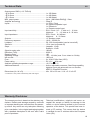
Technische Daten
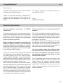
Garantiehinweis
Die Garantieleistung entspricht der gesetzlichen
Regelung. Von der Garantieleistung ausgeschlos-
sen sind Defekte und Schäden, die durch Überla-
stung oder unsachgemäße Behandlung entstanden
sind. Eine Rücksendung kann nur nach vorheriger
Absprache in der Originalverpackung, einer de-
taillierten Fehlerbeschreibung und einem gültigen
Kaufbeleg erfolgen.
Technische Änderungen, Druckfehler und Irrtümer
vorbehalten!
Für Schäden am Fahrzeug oder Gerätedefekte, her-
vorgerufen durch Bedienungsfehler des Gerätes,
können wir keine Haftung übernehmen. Dieses
Produkt ist mit einer CE-Kennzeichnung versehen.
Damit ist das Gerät für den Betrieb in Fahrzeugen
innerhalb der Europäischen Union (EU) zertiziert.
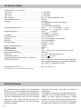
Leistung RMS (≤ 1% THD+N)
- @ 4 Ohm .................................................................... 1 x 350 Watt
- @ 2 Ohm .................................................................... 1 x 600 Watt
- @ 1 Ohm .................................................................... 1 x 900 Watt*
Max. Leistung ............................................................... Bis zu 1.000 Watt RMS @ 1 Ohm
Verstärkertechnologie ...................................................Class D
Eingänge ...................................................................... 1 x Cinch
2 x Hochpegel-Lautsprechereingang
1 x Remote In
1 x Fernbedienungseingang
Eingangsempndlichkeit ............................................... Cinch: 0,5 - 3 Volt oder 1 - 6 Volt
Hochpegel: 3 - 16 Volt oder 6 - 32 Volt
Eingangsimpedanz ....................................................... Cinch: 8,6 kOhm
Hochpegel: 9 - 33 Ohm
Ausgänge ..................................................................... 1 x Lautsprecherausgang
Frequenzbereich...........................................................10 Hz - 25.000 Hz
Tiefpass ........................................................................50 - 250 Hz regelbar (abschaltbar)
Subsonic .......................................................................15 Hz (abschaltbar)
Flankensteilheit............................................................. Tiefpass: 12 dB
Subsonic: 12 dB
Signal- / Rauschabstand ..............................................108 dB
Klirrfaktor (THD) ...........................................................0,002 %
Dämpfungsfaktor ..........................................................160
Betriebsspannung.........................................................10,5 - 18 Volt (max. 5 Sek. bis hinab zu 6 Volt)
Leerlaufstromaufnahme................................................1050 mA
Sicherung .....................................................................2 x 30 A LP-Mini-Stecksicherung
Leistungsaufnahme ......................................................DC 12 V 80 A max.
Umgebungstemperaturbereich für den Betrieb ............-40 °C bis +70 °C
Zusätzliche Features .................................................... Aktive, regelbare Frequenzweiche, Start-Stopfähig-
keit, Highlevel-Eingang mit automatischer Einschal-
tung, ADEP.3, DirectDSP-Funktion
Abmessungen (H x B x T) ............................................46 x 130 x 153 mm
* Dauerhafte 1 Ohm Leistung nur mit Musiksignal erreicht

11
Dear Customer,
Congratulations on your purchase of this innovative
and high-qual ity MATCH product.
Thanks to more than 30 years of experience in
research and development of audio products this
amplier sets new standards in the range of am-
pliers.
We wish you many hours of enjoyment with your
new MATCH UP 1FX.
Yours,
AUDIOTEC FISCHER
General installation instructions for MATCH
components
To prevent damage to the unit and possible injury,
read this manual carefully and follow all installation
instructions. This product has been checked for
proper function prior to shipping and is guaranteed
against manufacturing defects.
Before starting your installation, disconnect the
battery’s negative terminal to prevent damage
to the unit, re and / or risk of injury. For a proper
performance and to ensure full warranty coverage,
we strongly recommend to get this product installed
by an authorized MATCH dealer.
Install your UP 1FX in a dry location with sucient
air circulation for proper cooling of the equipment.
For safety reasons, the UP 1FX must be profes-
sionally installed. Therefore, use the two mounting
plates which are included in delivery. These are at-
tached to the bottom of the amplier with two short
screws which are included in delivery, too.
When screwing the amplier to the vehicle chassis,
carefully examine the area around and behind the
proposed installation location to ensure that there
are no electrical cables or components, hydraulic
brake lines or any part of the fuel tank located be-
hind the mounting surface. Failure to do so may re-
sult in unpredictable damage to these components
and possible costly repairs to the vehicle.
General instruction for connecting the UP 1FX
amplier
The UP 1FX amplier may only be installed in mo-
tor vehicles which have a 12 Volts negative terminal
connected to the chassis ground. Any other system
could cause damage to the amplier and the electri-
cal system of the vehicle.
The positive cable from the battery for the entire
sound system should be provided with a main fuse
at a distance of max. 30 cm from the battery. The
value of the fuse is calculated from the maximum
total current draw of the car audio system.
Use only suitable cables with sucient cable
cross-section for the connection of the UP 1FX.
The fuses of the amplier may only be replaced
by identically rated fuses (2 x 30 A) to avoid
damage of the amplier.
Prior to installation, plan the wire routing to avoid
any possible damage to the wire harness. All
cabling should be protected against possible
crushing or pinching hazards. Also avoid routing
cables close to potential noise sources such as
electric motors, high power accessories and other
vehicle harnesses.
Congratulations!
General instructions
en

12
Connectors and control units
1 2 3 4 5
1 Filter mode switch
Page 14, point 4
2 Lowpass lter control (LPF)
Page 16, point 1
3 Remote control input
Page 16, point 2
4 Clipping LED
Page 16, point 3
5 Gain control
Page 15, point 6
6 Lowlevel line input
Page 14, point 2
7 Highlevel speaker input
Page 14, point 3
8 Power & remote connector
Page 14, point 5
9 Control LED for internal fuses
Page 16, point 4
10 Status LED
Page 16, point 5
11 Speaker output
Page 15, point 7
8 9 10 11
6

13
Hardware conguration
Congure the MATCH UP 1FX as follows
Caution: Carrying out the following steps will
require special tools and technical knowledge. In
order to avoid connection mistakes and / or dam-
age, ask your dealer for assistance if you have any
questions and follow all instructions in this manual
(see page 11). It is recommended that this unit will
be installed by an authorized MATCH dealer.
1. Adjusting input voltage range
Before proceeding to adjust the input volt-
age range, please take note of the following
guidelines. This adjustment is only necessary
when connecting devices from the following
categories:
- Aftermarket radios with an output voltage
exceeding 3 V RMS
- Premium sound system ampliers with an
output power of more than 50 W RMS
- Stand-alone DSPs with an output voltage
exceeding 3 V RMS
For standard applications, such as connecting:
- Audiotec Fischer DSP ampliers using
RCA cables
- Factory radios
- Aftermarket radios with an output voltage
of less than 3 V RMS
this adjustment is not required. In such cases,
you can proceed directly to page 14, point 2.
To set the input voltage range, follow these
steps:
a. Open the amplier
Remove the side panel with the remote con-
trol input by loosening the three Allen screws
and sliding out the bottom panel to the side.
b. Determine the output voltage of the signal
source
We recommend measuring the maximum
output voltage using an appropriate mea-
suring device or contacting your authorized
MATCH dealer. If you are unsure, we recom-
mend setting the jumper to the „High Voltage
Range“ (Cinch 1 - 6 V / Highlevel 5 - 32 V) to
avoid potential damage to the device. To do
this, the jumper must be moved to the facto-
ry-unused multi-pin connector, as shown in
gure 2.
c. Place the jumper in the corresponding volt-
age range
To change the position of the jumper, simply
lift it upwards and insert it into the desired po-
sition. Ensure that the jumper is fully inserted
and not oset.
Overview of jumper positions:
Low voltage range conguration ( by default /
see g. 1):
Value range: HLI (Highlevel) 3 - 16 Volts
RCA /Cinch 0.5 - 3 Volts
High voltage range conguration
(see g.2):
Value range: HLI (Highlevel) 6 - 32 Volts
RCA / Cinch 1 - 6 Volts
Figure 1:
Figure 2:
d. Reassemble the amplier
en

14
2. Connecting the pre-amplier input
The lowlevel line input can be connected to
signal sources such as head units, radios,
DSPs and DSP ampliers using appropriate
cables. The input sensitivity can be optimal-
ly adapted to the signal source using the gain
control (see page 15, point 6).
Important: It is strictly forbidden to use the
Highlevel and lowlevel Line Input at the same
time as this may cause severe damage to the
signal source.
3. Connecting the highlevel speaker inputs
The highlevel loudspeaker inputs A and B can
be connected directly to the loudspeaker out-
puts of the signal source (e.g., head units, ra-
dios, DSPs, DSP ampliers) using appropriate
cables (loudspeaker cables with 1 mm² / AWG
18 max.).
The Highlevel Input is equipped with our pro-
prietary ADEP.3 circuit (Advanced Diagnostics
Error Protection 3rd generation) which ensures
that the car radio detects the amplier as a
speaker and thus neither any function of the ra-
dio (e.g. fader) will be deactivated nor any error
log in the CPU of the car will be created. If this
input is used, the remote input (REM) does not
need to be connected, as the amplier will au-
tomatically turn on once a loudspeaker signal
is applied.
Attention: Solely use the pluggable screw-ter-
minal for the highlevel connector included in the
delivery!
Important: It is strictly forbidden to use the
Highlevel and lowlevel Line Input at the same
time as this may cause severe damage to the
signal source.
4. Adjusting the lter mode of the internal
crossover
The UP 1FX is equipped with a DirectDSP func-
tion, which allows you to bypass the internal
crossover. You can activate or deactivate this
function using the X-Over switch (see page 12,
point 1).
DirectDSP: In this mode, the internal crossover
is deactivated, and the input signal is passed
unltered to the output stages of the amplier.
Bandpass: When the switch is set to this po-
sition, the internal crossover is active, and a
15 Hz highpass lter (Subsonic) is always ac-
tive. This means a bandpass is created. By
using the lowpass lter control (LPF, page 12,
point 2) the bandpass can be adjusted between
50 Hz and 250 Hz.
5. Connection to power supply & remote
Make sure to disconnect the battery before
installing the MATCH UP 1FX!
Ensure correct polarity.
+12 V: Connector for the positive cable.
Connect the +12 V power cable to the positive
terminal of the battery. The positive wire from
the battery to the ampliers power terminal
needs to have an inline fuse at a distance of
no more than 12 inches (30 cm) from the bat-
tery. The value of the fuse is calculated from
the maximum total current input of the whole
car audio system (UP 1FX = max. 60 A RMS at
12 V RMS power supply). If your power wires
are short (less than 1 m / 40”) then a wire gauge
of 16 mm² / AWG 6 will be sucient. In all other
cases we strongly recommend gauges of 25 -
35 mm² / AWG 4 – 2!
GND: Connector for the ground cable. The
ground wire should be connected to a common
ground reference point (this is located where
the negative terminal of the battery is grounded
to the metal body of the vehicle) or to a pre-
pared metal location on the vehicle chassis, i.e.,
an area cleaned of all paint residues. The cable
should have the same gauge as the +12 V wire.
Inadequate grounding causes audible interfer-
ence and malfunctions.
REM: The remote input is used to switch on and
o the UP 1FX. It is mandatory to connect this in-
put to the remote output of the preconnected de-
vice that provides the input signal to the UP 1FX.
Hardware conguration

15
en
This input does not need to be assigned if the
highlevel input is used.
We do not recommend controlling the remote
input via the ignition switch to avoid pop noise
during turn on / o.
6. Adjustment of the input sensitivity
ATTENTION: It is mandatory to properly
adapt the input sensitivity of the UP 1FX to
the signal source to achieve the best possi-
ble signal quality and avoid damage to the
amplier. It is also mandatory to adjust the
“Voltage Range” to the output voltage of
your signal source (see page 13, point 1).
The input sensitivity can be optimally adapt-
ed to the signal source using the gain control
(page 12, point 5).
This is not a volume control; it’s only for adjust-
ing the amplier gain. The setting of the control
aects both the Highlevel and lowlevel Line In-
put.
Input sensitivity is factory set to 16 Volts (high-
level) and 3 Volts (RCA / Cinch). This is denite-
ly the best setting in most applications.
The Gain control ranges are:
Low Voltage Range conguration:
Highlevel: 3 - 16 Volts
RCA / Cinch: 0.5 - 3 Volts
High Voltage Range conguration:
Highlevel: 6 - 32 Volts
RCA / Cinch: 1 - 6 Volts
If the signal source provides a lower output
voltage, the input sensitivity can be smoothly
increased via the Gain Control.
If your signal source delivers a higher output
voltage – for example, if a factory-installed
amplier serves as a signal source – the input
sensitivity must be lowered via the control, and
the correct conguration of the “Voltage Range”
jumper must be checked.
If you are not sure regarding the signal source’s
output voltage, please contact your MATCH
specialist dealer.
The Clipping LED (see page 12, point 4) serves
as monitoring tool.
Note: Don‘t connect any loudspeakers to the
outputs of the amplier during this setup.
For adjustment please proceed as follows:
1. Turn on the amplier.
2. Adjust the volume of your radio to approx.
90 % of the max. volume and playback an
appropriate test tone, e.g., pink noise (0 dB).
3. If the Clipping LED already lights up, you
have to reduce the input sensitivity via the Gain
Control until the LED turns o.
4. Increase the input sensitivity by turning the
Gain Control clockwise until the Clipping
LED lights up. Now turn the control coun-
terclockwise until the Clipping LED turns o
again.
7. Connecting the loudspeaker outputs
The loudspeaker outputs can be connected di-
rectly to the wires of the loudspeakers. Never
connect any of the loudspeaker cables with the
chassis ground as this will damage your ampli-
er and your speakers. Ensure that the loud-
speakers are correctly connected (in phase),
i.e., plus to plus and minus to minus.
Exchanging plus and minus causes a total loss
of bass reproduction. The plus pole is indicated
on most speakers. The impedance must not be
lower than 1 Ohm, otherwise, the amplier pro-
tection will be activated. Examples for speaker
congurations can be found on page 17 et sqq.
8. Filter settings
When using the DirectDSP function (see
page 14, point 4), adjust crossover frequencies
in the preconnected DSP or DSP amplier. For
bandpass function, use the lowpass lter con-
trol (LPF) on the device. In this case, a 15 Hz
high-pass lter (subsonic) is always active.

16
Additional functions
1. Lowpass lter control (LPF)
This control allows you to adjust the lowpass l-
ter of the bandpass between 50 Hz and 250 Hz.
The control is activated when the X-Over switch
is set to “Bandpass” (see page 14, point 4).
2. Remote control input
This input is used for connecting an optional-
ly available remote control. The remote control
can be used to adjust the volume of the sub-
woofer.
3. Clipping LED
Normally, the Clipping LED is o and only lights
up if the lowlevel Line Input or one of the High-
level Inputs is overdriven.
On (red): One of the analog signal inputs is over-
driven. Reduce the input sensitivity using the
Gain Control until the LED goes out. Instructions
on how to reduce the input sensitivity are de-
scribed on page 15, point 6.
4. Fuse LED
The LED indicates the status of the internal fus-
es.
O: Fuses are intact.
On (red): The internal fuses are blown. They
may only be replaced by identically rated fus-
es (2 x 30 A) to avoid damage of the amplier.
Using higher-rated fuses can lead to dangerous
consequential damage!
5. Status LED
The Status LED indicates the operating mode
of the amplier.
Green: The amplier is ready for operation.
Orange: There is a short circuit at the speak-
er output or a faulty connection. In this case,
check all connections for errors.
Red: Protection Mode active. A malfunction has
occurred that may have dierent root causes.
The amplier is equipped with protection cir-
cuits against over- and undervoltage as well
as overheating. Please check for connecting
failures such as short-circuits or other incorrect
connections. If the amplier is overheated, the
internal temperature protection will turn o the
signal output until it reaches a safe temperature
level again. If the amplier does not turn on, it
is defective and needs to be sent to your local
authorized dealer for repair service.

17
en
Mono subwoofer application
Subwoofer with one voice coil (single voice coil)
RMS output power ≤ 1% THD+N:
1 x 4 Ohms: 350 Watts
1 x 2 Ohms: 600 Watts
1 x 1 Ohm: 900 Watts
Note: If you have activated the DirectDSP function, the crossover frequencies for the subsonic
or lowpass must be set in the preconnected DSP / DSP amplier.
Parallel operation
Two subwoofers with one voice coil (single voice coil) or one
subwoofer with dual voice coil are connected in parallel.
Note: The parallel connection of two voice coils will result in
halving the impedance!
RMS output power ≤ 1% THD+N:
Two subwoofers with 1 x 4 Ohms correspond to a total
impedance of 2 Ohms: 600 Watts
One subwoofer with 2 x 4 Ohms also corresponds to a total
impedance of 2 Ohms: 600 Watts
Two subwoofers with 1 x 2 Ohms correspond to a total
impedance of 1 Ohm: 900 Watts
One subwoofer with 2 x 2 Ohms also corresponds to a total
impedance of 1 Ohm: 900 Watts
Note: The parallel connection of 1 Ohm voice coils will result in
shutdown of the amplier.
Conguration examples
Ein Subwoofer mit
Doppelschwingspule
(Dual Voice Coil)
Zwei Subwoofer mit einer
Schwingspule
(Single Voice Coil)

18
Ein Subwoofer mit
Doppelschwingspule
(Dual Voice Coil)
Zwei Subwoofer mit einer
Schwingspule
(Single Voice Coil)
Conguration examples
In series
Two subwoofers with one voice coil (single voice coil) or one
subwoofer with dual voice coil are connected in series.
Note: The connection of two voice coils in series will result in
doubling the impedance!
RMS output power ≤ 1% THD+N:
Two subwoofers with 1 x 2 Ohms correspond to a total
impedance of 4 Ohms: 350 Watts
One Subwoofer with 2 x 2 Ohms also corresponds to a total
impedance of 4 Ohms: 350 Watts
Two subwoofers with 1 x 1 Ohm correspond to a total
impedance of 2 Ohms: 600 Watts
One subwoofer with 2 x 1 Ohm also correspond to a total
impedance of 2 Ohms: 600 Watts
Note: The negative terminal of the rst voice coil has to be con-
nected to the positive terminal of the second voice coil by using
a speaker wire with the same gauge as the other speaker.

19
en
Output power RMS (≤ 1% THD+N)
- @ 4 Ohms ..................................................................1 x 350 Watts
- @ 2 Ohms ..................................................................1 x 600 Watts
- @ 1 Ohms ..................................................................1 x 900 Watts*
Max. output power ........................................................ Up to 1,000 Watts RMS @ 1 Ohm
Amplier technology .....................................................Class D
Inputs ............................................................................ 1 x RCA / Cinch
2 x Highlevel speaker input
1 x Remote In
1 x Remote control input
Input sensitivity ............................................................. RCA / Cinch: 0.5 - 3 Volts or 1 - 6 Volts
Highlevel: 3 - 16 Volts or 6 - 32 Volts
Input impedance ........................................................... RCA / Cinch: 8.6 kOhms
Highlevel: 9 - 33 Ohms
Outputs ......................................................................... 1 x Speaker output
Frequency response .....................................................10 Hz - 25,000 Hz
Lowpass .......................................................................50 - 250 Hz adjustable (can be turned o)
Subsonic .......................................................................15 Hz (can be turned o)
Slope ............................................................................ Lowpass: 12 dB
Subsonic: 12 dB
Signal-to-noise ratio......................................................108 dB
Distortion (THD) ............................................................0.002 %
Damping factor .............................................................160
Operating voltage .........................................................10.5 - 18 Volts (max. 5 sec. down to 6 Volts)
Idle current....................................................................1050 mA
Fuse..............................................................................2 x 30 A LP-Mini-fuse (APS)
Power rating .................................................................DC 12 V 80 A max.
Ambient operating temperature range ..........................-40 °C to +70 °C
Additional features ........................................................ Active, adjustable crossover, Start-Stop capability,
highlevel input with automatic turn on function,
ADEP.3, DirectDSP function
Dimensions (H x W x D) ...............................................46 x 130 x 153 mm / 1.81 x 5.12 x 6.02”
* Continuous 1 Ohm power achieved only with music signal
Technical Data
The warranty service is based on the statutory reg-
ulations. Defects and damage caused by overload
or improper handling are excluded from the warran-
ty service. Any return can only take place following
prior consultation, in the original packaging together
with a detailed description of the error and a valid
proof of purchase.
Technical modications, misprints and errors ex-
cepted! We accept no liability for damage to the
vehicle or device defects caused by the incorrect
operation of the device. This product has been is-
sued a CE marking. This means that the device
is certied for use in vehicles within the European
Union (EU).
Warranty Disclaimer

Audiotec Fischer GmbH
Hünegräben 26 · 57392 Schmallenberg · Germany
Tel.: +49 2972 9788 0 · Fax: +49 2972 9788 88
E-mail: match@audiotec-scher.com · Internet: www.audiotec-scher.com
Made in China
-
 1
1
-
 2
2
-
 3
3
-
 4
4
-
 5
5
-
 6
6
-
 7
7
-
 8
8
-
 9
9
-
 10
10
-
 11
11
-
 12
12
-
 13
13
-
 14
14
-
 15
15
-
 16
16
-
 17
17
-
 18
18
-
 19
19
-
 20
20


Audiotec Fischer MATCH UP 1FX Bedienungsanleitung
- Kategorie
- Musikausrüstung
- Typ
- Bedienungsanleitung
in anderen Sprachen
Verwandte Artikel
-
 Audiotec Fischer MATCH UP 10DSP – 24V Edition Bedienungsanleitung
-
 Audiotec Fischer HELIX M ONE X - 24V Edition Bedienungsanleitung
-
Helix HELIX P TWO Bedienungsanleitung
-
 Audiotec Fischer MATCH UP 8DSP Bedienungsanleitung
-
 Audiotec Fischer HELIX P SIX DSP ULTIMATE Bedienungsanleitung
-
 Audiotec Fischer HELIX V TWELVE DSP Bedienungsanleitung
-
-
 Audiotec Fischer HELIX P ONE Bedienungsanleitung
-
 Audiotec Fischer HELIX G FIVE Bedienungsanleitung


