
Guía Rapída
Australia
Datalogic Scanning Pty Ltd
North Ryde, Australia
Telephone: [61] (2) 9870 3200
Fax: [61] (2) 9878 8688
France and Benelux
Datalogic Scanning Sarl
LES ULIS Cedex, France
Telephone: [33].01.64.86.71.00
Fax: [33].01.64 46.72.44
Germany
Datalogic Scanning GmbH
Darmstadt, Germany
Telephone: 49 (0) 61 51/93 58-0
Fax: 49 (0) 61 51/93 58 58
Italy
Datalogic Scanning SpA
Vimercate (MI), Italy
Telephone: [39] (0) 39/62903.1
Fax: [39] (0) 39/6859496
Japan
Datalogic Scanning KK
Shinagawa, Tokyo, Japan
Telephone: 81 (0)3 3491 6761
Fax: 81 (0)3 3491 6656
Latin America
Datalogic Scanning, Inc
Miami, Florida, USA
Telephone: (305) 591-3222
Fax: (305) 591-3007
Spain and Portugal
Datalogic Scanning Sarl
Sucursal en España
Madrid, Spain
Telephone: 34 91 746 28 60
Fax: 34 91 742 35 33
United Kingdom
Datalogic Scanning LTD
Watford, England
Telephone: 44 (0) 1923 809500
Fax: 44 (0) 1923 809 505
www.scanning.datalogic.com
Datalogic Scanning, Inc.
959 Terry Street
Eugene, OR 97402
Telephone: (541) 683-5700
Fax: (541) 345-7140
©2007 Datalogic Scanning, Inc. 822000143 (Rev. C) 09/07
STAR Modem™
Kurzanleitung
Guide Rapide
Quick Reference Guide
Guida Rapida

Datalogic Scanning, Inc.
959 Terry Street
Eugene, Oregon 97402
Telephone: (541) 683-5700
Fax: (541) 345-7140
An Unpublished Work - All rights reserved. No part of the contents of this
documentation or the procedures described therein may be reproduced or
transmitted in any form or by any means without prior written per-mission of
Datalogic Scanning, Inc. or its subsidiaries or affiliates ("Datalogic" or “Datalogic
Scanning”). Owners of Datalogic products are hereby granted a non-exclusive,
revocable license to reproduce and transmit this documentation for the purchaser's
own internal business purposes. Purchaser shall not remove or alter any proprietary
notices, including copyright notices, contained in this documentation and shall ensure
that all notices appear on any reproductions of the documentation.
Should future revisions of this manual be published, you can acquire printed versions
by contacting your Datalogic representative. Electronic versions may either be
downloadable from the Datalogic website (www.scanning.datalogic.com) or provided
on appropriate media. If you visit our website and would like to make comments or
suggestions about this or other Datalogic publications, please let us know via the
"Contact Datalogic" page.
Disclaimer
Datalogic has taken reasonable measures to provide information in this manual that
is complete and accurate, however, Datalogic reserves the right to change any
specification at any time without prior notice. Datalogic is a registered trademark of
Datalogic S.p.A. in many countries and the Datalogic logo is a trademark of Datalogic
S.p.A. all licensed to Datalogic Scanning, Inc. All other trademarks and trade names
referred to herein are property of their respective owners.

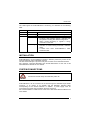
iii
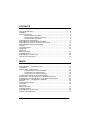
CONTENTS
Using STARModem™.............................................................................................. 2
Installation................................................................................................................... 3
System Connections ................................................................................................... 3
RS232 Interface Connection......................................................................... 4
Pen Emulation Interface Connection............................................................. 4
Wedge Interface Connection......................................................................... 5
STARModem™ Initial Setup .................................................................................... 5
STARModem™ Setup for Stand Alone Mode............................................................. 7
STARModem™ Setup for STAR-System™ Mode ................................................. 10
STARModem™ Default Configuration ................................................................... 12
Warranty ................................................................................................................... 12
Technical Features ................................................................................................... 13
Compliance ............................................................................................................... 13
Antenna 67
Mounting Brackets .................................................................................................... 67
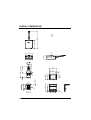
Overall Dimensions................................................................................................... 68
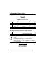
STARModem™ Cable Pinout ................................................................................ 69
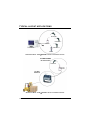
Typical Layout Applications....................................................................................... 70
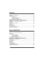
INDICE
STARModem™ - Descrizione e Uso...................................................................... 16
Installazione .............................................................................................................. 17
Sistema Radio - Collegamento ................................................................................. 17
Connessione con Interfaccia RS232........................................................... 18
Connessione con Interfaccia Pen ............................................................... 18
Connessione con Interfaccia Wedge .......................................................... 18
Configurazione Preliminare di STARModem™...................................................... 19
Configurazione di STARModem™ in Modalità Stand-Alone.................................. 21
Configurazione di STARModem™ in Modalità STAR-System™ ........................... 24
STARModem™ - Configurazione di Default .......................................................... 25
Garanzia ................................................................................................................... 25
Caratteristiche Tecniche ........................................................................................... 26
Conformità ................................................................................................................ 26
Antenna 67
Mounting Brackets .................................................................................................... 67
Overall Dimensions................................................................................................... 68
STARModem™ Cable Pinout ................................................................................ 69
Typical Layout Applications....................................................................................... 70

iv
SOMMAIRE
Utilisation de STARModem™ ................................................................................ 28
Installation................................................................................................................. 29
Connexion Systeme.................................................................................................. 29
Connexion RS232....................................................................................... 30
Connexion Emulation Crayon ..................................................................... 30
Connexion Interclavier ................................................................................ 31
Configuration Initiale de STARModem™ ............................................................... 31
Configuration de STARModem™ en Mode Monoposte......................................... 33
Configuration de STARModem™ en Mode STAR-System™ ................................ 36
STARModem™ - Configuration par Defaut............................................................ 38
Garantie 38
Caracteristiques Techniques..................................................................................... 39
Conformite ................................................................................................................ 40
Antenna 67
Mounting Brackets .................................................................................................... 67
Overall Dimensions................................................................................................... 68
STARModem™ Cable Pinout ................................................................................ 69
Typical Layout Applications....................................................................................... 70
INHALTSVERZEICHNIS
Beschreibung und Gebrauchsanweinsung................................................................ 42
Installation................................................................................................................. 43
Systemanschluß ....................................................................................................... 43
RS232 - Schnittstelle .................................................................................. 44
Lesestiftschnittstelle.................................................................................... 44
Tastaturschnittstelle .................................................................................... 44
STARModem™ Anfangskonfiguration ................................................................... 45
STARModem™ Konfiguration für Stand-Alone-Mode........................................... 47
STARModem™ Konfiguration für STAR-System™ Mode .................................... 50
STARModem™ Grundeinstellung.......................................................................... 51
Gewährleistung ......................................................................................................... 51
Technische Daten ..................................................................................................... 52
Konformität................................................................................................................ 52
Antenna 67
Mounting Brackets .................................................................................................... 67
Overall Dimensions................................................................................................... 68
STARModem™ Cable Pinout ................................................................................ 69
Typical Layout Applications....................................................................................... 70

v
INDICE
Utilización de los STARModem™.......................................................................... 54
Instalación................................................................................................................. 55
Conexión del Sistema ............................................................................................... 55
Conexión RS232......................................................................................... 56
Conexión Emulación Lápiz.......................................................................... 56
Conexión Emulación Teclado ..................................................................... 56
Configuración Inicial del STARModem™............................................................... 57
Configuración del STARModem™ en Modo de Configuración Unitaria................. 59
Configuración del STARModem™ en Modo de Configuración STAR-System™... 63
STARModem™ - Configuración Predefinida ......................................................... 64
Garantia 65
Características Técnicas........................................................................................... 65
Conformidad ............................................................................................................. 66
Antenna 67
Mounting Brackets .................................................................................................... 67
Overall Dimensions................................................................................................... 68
STARModem™ Cable Pinout ................................................................................ 69
Typical Layout Applications....................................................................................... 70

vi

1
STARModem™
RADIO MODEM
QUICK REFERENCE GUIDE

STARMODEM™
2
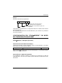
USING STARModem™
STARModem™ is a radio modem developed to provide wireless
433 MHz (European models) / 910 MHz (USA model) RF communication between
any serial device (Host) and Datalogic RF devices or base stations, such as:
- Gryphon™ M Readers
- Dragon™ M Laser Scanners
- STARModem™ Radio Modems
- Formula Basic Line RF Terminals (F734-E/RF, F725-E/RF, F660-E/RF)*
- STARGATE™ Base Stations
* not compatible with STAR
Modem™ USA model.
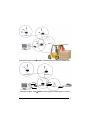
STARModem™ can be used in two different modes: Stand Alone mode and
STAR-System™ mode.
In Stand Alone mode, STARModem™ can be setup in uni-directional
communication to either receive (Server) data via radio from Datalogic RF devices, or
transmit (Client) data via radio to Datalogic RF devices. When working as Server,
currently supported devices are RF hand-held readers, another STARModem™ or
RF terminals loading STAR&Play™ software (not compatible with STARModem™
USA model). All the multistandard interface selections are valid (RS232, Wedge, Pen
Emulation).
When working as Client, currently supported devices are another STARModem™
or a Datalogic OM-cradle. The only valid interface selection in RS232.
In Stand Alone mode, the system implements a different RF Narrow Band radio
protocol than STAR-System™.
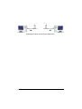
In STAR-System™ mode, STARModem™ uniquely provides a wireless
bi-directional communication between the Host and the RF devices.
STARModem™ is connected to the Host only through the RS232 interface.
For more details about the modem configuration options refer to the
STARModem™ Reference Manual provided on the installation CD-ROM.

DATALOGIC
3
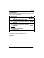
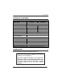
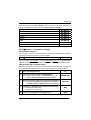
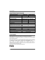
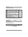
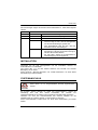
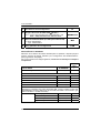
The LEDs signal the STARModem™ functioning, as described in the following
table:
LED DESCRIPTION
Power On Green constant STARModem™ is powered.
TX/RX Yellow blinking STARModem™ is receiving or transmitting data.
Off STARModem™ is working correctly.
Status
Red constant - at startup, after firmware upload, it indicates that
the system is working with default configuration.
- during normal functioning it signals a wrong
connection to the Host.
Red blinking - it blinks during a programming command
execution. In case of wrong command, it will blink
faster.
- It blinks once when STARModem™ radio
transaction fails.
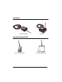
INSTALLATION
STARModem™ can be installed to operate in different positions by means of two
mounting brackets and an adjustable antenna.
The four screw holes (M4 x 5) on the body of the modem are for mechanical fixture.
See "Antenna", "Mounting Brackets" and "Overall Dimensions" at the end of this
Quick Reference Manual for more details.
SYSTEM CONNECTIONS
CAUTION
Connections should always be made with power off!
STARModem™ can be connected to the Host through the dedicated 9-pin female
connector, or by means of an adapter and the Datalogic standard cable
corresponding to the desired interface. In addition, a power supply must be
connected to the power jack provided on the same connector.
See "STARModem™ Cable Pinout" at the end of this Quick Reference Manual for
more details.

STARMODEM™
4
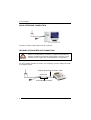
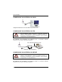
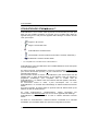
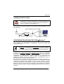
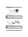
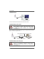
RS232 INTERFACE CONNECTION
Connect the modem cable directly to the PC COM Port.
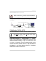
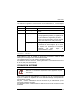
PEN EMULATION INTERFACE CONNECTION
CAUTION
Before proceeding with this connection, configure STAR
Modem™
software parameters through the RS232 interface and then set the
hardware jumper position (see "STAR
Modem™ Configuration").
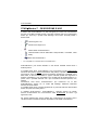
For Pen Emulation interface connection, it is necessary to use the adapter as shown
in the following figure:
STARModem™ Adapter
90ACC1859
Datalogic Standard Pen Emulation Cable

DATALOGIC
5
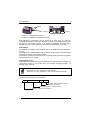
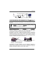
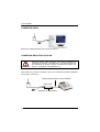
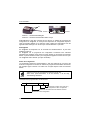
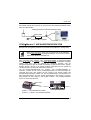
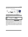
WEDGE INTERFACE CONNECTION
CAUTION
Before proceeding with this connection, configure STAR
Modem™
software parameters through the RS232 interface and then set the
hardware jumper position (see "STAR
Modem™ Configuration").
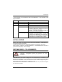
For Wedge interface connection, it is necessary to use the adapter as shown in the
following figure:
STARModem™ INITIAL SETUP
For a correct STARModem™ configuration, keep in mind the following guidelines.
NOTE
When using the modem for the first time, set the desired
STAR
Modem™ address via RS232 serial interface, since its factory
default address is "Undefined".
For Stand Alone configurations using Wedge/Pen Emulation interface connections,
set all parameters via RS232 interface using either the DL Sm@rtSet software
program or sending configuration strings to STARModem™. Then, set the correct
hardware jumper position as indicated in the table given in "STARModem™ Setup
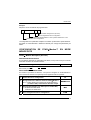
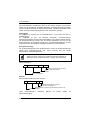
For Stand Alone Mode" (see also the figure below).
For changing any configuration parameter in Wedge/Pen Emulation interface
connections, send the new configuration commands via radio using Datalogic RF
devices. Otherwise, set the jumper in the RS232 position (RS232 communication
parameters are set to default values) to send the configuration strings to
STARModem™ via serial interface and set the jumper back in the Wedge/Pen
Emulation position to enable this kind of connection.
STARModem™ Adapter
90ACC1859
Datalogic Standard Wedge Cable

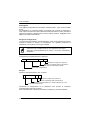
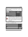
STARMODEM™
6
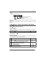
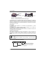
Position 1 = RS232/Digital interface
Position 2 = Wedge/Pen Emulation interface
STARModem™ configuration can be performed in three ways: by using the
DL Sm@rtSet software configuration program, by sending configuration strings from
the Host via the RS232 interface or by reading configuration barcodes with a
Datalogic RF device and sending the commands to STARModem™ via radio.
DL Sm@rtSet
DL Sm@rtSet is available on the STARModem™ CD-ROM and can be installed on
your PC.
DL Sm@rtSet is a Windows-based utility program providing a quick and user-friendly
configuration method via the RS232 interface.
It also allows upgrading the software of the connected device (see the DL Sm@rtSet
User's Manual for more details).
Configuration Strings
STARModem™ initial setup must be performed via serial interface by sending the
configuration strings to the modem using any terminal emulation program, for
example Hyper Terminal.
NOTE
Ensure that your PC COM port is set as follows:
9600 baud, no parity, 8 data bits, 1 stop bit, handshaking disabled.
The programming sequence is the following:
$+ Command $-CR
Enter configuration environment
Character sequence in following tables
Exit and Save configuration
Carriage return character (0D Hex.)
Position 1 Position 2
Screws

DATALOGIC
7
Example
Command programming sequence:
$+ MA0RC1237 $- CR
Enter configuration environment
Carriage return character (0D Hex.)
STAR-Modem address in Stand Alone system: 1237
Exit and Save configuration
Each configuration parameter setting removes the condition previously active for that
parameter.
Refer to the STARModem™ Reference Manual for changing the default
parameters.
STARModem™ SETUP FOR STAND ALONE MODE
STAR Modem Receiver (Server)
RESTORE DEFAULT
Whenever necessary, send the following string to STARModem™ via RS232 to
restore its default values:
Restore STARModem™ Default $+$*CR
This command does not change the STARModem™ address nor the RF Baud
Rate parameters.
SET RADIO ADDRESS
Follow the procedure below to set the STARModem™ radio address and prepare it
to receive data from the RF devices of the system:
1. Enter Configuration $+
2. Set STARModem™ Radio Address
xxxx = four digits for the STARModem™ address (from
0000 to 1999). This address must be unique.
MA0RCxxxx
3. Set RF Baud Rate (not for USA model)
x = 0 defines 9600 baud
1 defines 19200 baud
MFx
4. Exit and Save Configuration $-CR

STARMODEM™
8
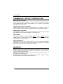
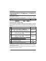
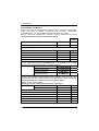
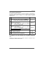
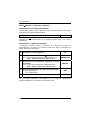
INTERFACE SELECTION
Select the desired interface string for your application, then set the correct hardware
jumper position (see "STARModem™ Initial Setup" for jumper setting).
Among the following interface selection strings, send only the string that suits
your application:
Jumper
Position
RS232 Interface $+CP0$-CR 1
Pen Emulation Interface $+CP6$-CR 2
Wedge Interface
IBM AT or PS/2 PCs $+CP500$-CR 2
IBM XT $+CP503$-CR 2
PC Notebook $+CP505$-CR 2
IBM SURE1 $+CP506$-CR 2
IBM Terminal 3153 $+CP504$-CR 2
IBM Terminals 31xx, 32xx, 34xx, 37xx
To select the interface for these IBM Terminals, send the correct KEY
TRANSMISSION string. Select the KEYBOARD TYPE if necessary (default =
advanced keyboard).
Make-only keyboard
$+CP502$-CR 2
Make-break keyboard
$+CP501$-CR 2
Advanced keyboard $+FK1$-CR 2
Typewriter keyboard
$+FK0$-CR 2
ALT MODE
The ALT-mode selection allows barcodes sent to the PC to be interpreted correctly
independently from the Keyboard Nationality used. You do not need to make a
Keyboard Nationality selection.
(default = Num Lock Unchanged).
Make sure the Num Lock key on your keyboard is ON.
IBM AT- ALT mode $+CP507$-CR 2
PC Notebook - ALT mode $+CP508$-CR 2
Wyse Terminal - ANSI Keyboard $+CP509$-CR 2
Wyse Terminal - PC Keyboard $+CP510$-CR 2
Wyse Terminal - ASCII Keyboard $+CP511$-CR 2
Wyse Terminal - VT2200 style Keyboard $+CP514$-CR 2
APPLE ADB Bus $+CP513$-CR 2
Digital Terminal VT2xx/3xx/4xx $+CP512$-CR 1

DATALOGIC
9
CAUTION
For changing the configuration parameters when using the Digital
Terminal interface, send the new values via radio through Datalogic
RF devices. Otherwise, send the $+CP0$-CR string via radio to set
the RS232 interface and define the parameters via serial interface.
This operation sets the RS232 parameters to default values and
erases the current header and terminator selection. Thus, after
configuration setting, you must restore the Digital Terminal interface,
Header and Terminator selection by sending a command string
similar to the one given in the following example:
$+CP512EA0141EA1102$-CR.
If you selected the Wedge interface, you should also send among the following
strings the one the matches your Keyboard Nationality:
English $+FJ4$-CR
Deutsch $+FJ3$-CR
Svenskt $+FJ5$-CR
Français $+FJ2$-CR
Italiano $+FJ1$-CR
USA $+FJ0$-CR
Español $+FJ6$-CR
Belge $+FJ7$-CR
STAR Modem Transmitter (Client)
RESTORE DEFAULT
Whenever necessary, send the following string to STARModem™ via RS232 to
restore its default values:
Restore STARModem™ Default $+$*CR
This command does not change the STARModem™ address nor the address of
the Stand Alone destination device, nor the RF Baud Rate parameters.

STARMODEM™
10
SET RADIO ADDRESS
Follow the procedure below to set the STARModem™ radio address and prepare it
to transmit data to the destination device of the system:
1. Enter Configuration $+
2. Set STARModem™ Radio Address
xxxx = four digits for the STARModem™ address (from
0000 to 1999). This address must be unique.
MA0RCxxxx
3. Address of the Stand Alone Destination Device
xxxx = four digits for the address of the Stand Alone
Destination Device (from 0000 to 1999).
This address must be unique.
MSxxxx
4. Set RF Baud Rate (not for USA model)
x = 0 defines 9600 baud
1 defines 19200 baud
MFx
5. Exit and Save Configuration $-CR
No interface selection is required, since STARModem™ can transmit data only if
connected to the Host via its RS232 serial interface.
STARModem™ SETUP FOR STAR-System™ Mode
RESTORE DEFAULT
Whenever necessary, send the following string to STARModem™ via RS232 to
restore its default values:
Restore STARModem™ Default $+$*CR
This command does not change the STARModem™ address nor the
address of the STAR-System™ destination devices, nor the RF Baud Rate
parameters.

DATALOGIC
11
SET RADIO ADDRESSES
Follow the procedure below to set the STARModem™ radio address and prepare it
to receive and transmit data to all devices included in the range from the First to the
Last STAR-System™ destination device.
1. Enter Configuration $+
2. Set STARModem™ Radio Address
xxxx = four digits for the STARModem™ address (from
0000 to 1999). This address must be unique.
MA1RCxxxx
3. First STAR-System™ Destination Device Address
xxxx = four digits for the Destination Device address (from
0000 to 1999).
MSxxxx
4. Last STAR-System™ Destination Device Address
xxxx = four digits for the Destination Device address (from
0000 to 1999).
If transmitting to one Destination device only, this selection
is not required.
MTxxxx
5. Set RF Baud Rate (not for USA model)
x = 0 defines 9600 baud
1 defines 19200 baud
MFx
6. Exit and Save Configuration $-CR
When defining a range of destination device addresses, STARModem™ activates
roaming towards all the devices included within this range.
No interface selection is required, since all STAR-System™ transactions occur via
serial interface.

STARMODEM™
12
STARModem™ DEFAULT CONFIGURATION
RS232 DEFAULT SETTINGS
9600 baud, parity disabled, 8 data bits, 1 stop bit, handshaking disabled, ACK/NACK
protocol disabled, inter-character delay disabled, 5 sec. rx timeout, FIFO enabled,
frame packing = frame + [CR].
PEN EMULATION DEFAULT SETTINGS
Interpret operating mode, minimum output pulse 600 µs, conversion to Code 39,
overflow medium, output level normal, idle level normal, inter-block delay disabled.
WEDGE DEFAULT SETTINGS
USA keyboard, caps lock off, num lock unchanged, inter-character and intercode
delay disabled, control character emulation = Ctrl + Shift + Key.
DATA FORMAT
Code identifier disabled, no header, terminator: RS232 = CR-LF; WEDGE = ENTER,
header position = first frame field, code length tx not transmitted, address stamping
disabled, address delimiter disabled.
RADIO PARAMETERS
Transmission mode 1 way, radio protocol timeout 2 sec., single store disabled,
ACK/NACK from remote host disabled, RF baud rate 19200 (European models),
fixed RF baud rate 36800 (USA model), beacon disabled.
WARRANTY
Datalogic warranties this product against defects in workmanship and materials, for a
period of 24 months from the date of shipment, provided that the product is operated
under normal and proper conditions.
Datalogic has the faculty to repair or replace the product; these provisions do not
prolong the original warranty term.
The warranty does not apply to any product that has been subject to misuse,
accidental damage, unauthorized repair or tampering.

DATALOGIC
13
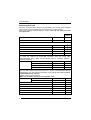
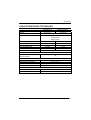
TECHNICAL FEATURES
Electrical Features 5 Volt Models 10 Volt Models
Supply voltage 5 Vdc ±5% 10 to 30 Vdc
Power consumption 2 W
Indicators Power On (green); TX/RX (yellow); Status (red)
Radio Features European Models USA Models
Working frequency 433.92 Mhz 910 Mhz
Bit rate Up to 19200 baud 36800 baud
Effective Radiated Power <10 mW <1 mW
Range (in open air) 50 m / 164 ft 30 m / 98.4 ft
RF Modulation FSK
System Configuration
Maximum number of devices
per STARModem™ 32
Environmental Features
Working temperature -20° to +50 °C / -4° to +122 °F
Storage temperature -20° to +70 °C / -4° to +158 °F
Humidity 90% non condensing
Protection class IP64
Mechanical Features
Weight 370 gr / 13.1 oz
Dimensions (without antenna) 68 x 84 x 34 mm / 2.68 x 3.3 x 1.3 in
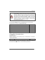
COMPLIANCE
This device must be opened by qualified personnel only.
Modifications or changes to this equipment without
expressed written approval of Datalogic could void the
authority to use the equipment.
This device complies with PART 15 of the FCC Rules.
Operation is subject to the following two conditions: (1)
This device may not cause harmful interference, and (2)
this device must accept any interference received,
including interference which may cause undesired
operation.

STARMODEM™
14
This equipment has been tested and found to comply with the limits for a Class B
digital device, pursuant to part 15 of the FCC Rules. These limits are designed to
provide reasonable protection against harmful interference in a residential
installation. This equipment generates, uses and can radiate radio frequency energy
and, if not installed and used in accordance with the instructions, may cause harmful
interference to radio communications. However, there is no guarantee that
interference will not occur in a particular installation. If this equipment does cause
harmful interference to radio or television reception, which can be determined by
turning the equipment off and on, the user is encouraged to try to correct the
interference by one or more of the following measures:
- Reorient or relocate the receiving antenna.
- Increase the separation between the equipment and receiver.
- Connect the equipment into an outlet on a circuit different from that to which the
receiver is connected.
- Consult the dealer or an experienced radio/TV technician for help.
STARModem™ is a Class III equipment according to the EN-60950 Electrical
Safety Standard.
CLASS III Equipment:
This equipment is intended for use with UL or CSA Certified, detachable, Class 2
Power Supply (SELV provided by Limited Power Source incorporating isolating
transformer), rated output:
5 Volt models: 5 V dc, 0.2-5 A
10-30 Volt models: 10-20 V dc, 0.2-5 A or 20-30 V dc 0.2-3.3 A
DC supply voltage is 5 Vdc ±5% for 5 Volt models, 10 to 30 Vdc for 10-30 Volt
models, intended to be powered by a Class 2 power unit with a cable length
< 3m.
Contact the competent authority responsible for the management of radio frequency
devices of your country to verify the eventual necessity of a user license.
Refer to the web site http://europa.eu.int/comm/enterprise/rtte/spectr.htm for further
information.
N263
Seite laden ...
Seite laden ...
Seite laden ...
Seite laden ...
Seite laden ...
Seite laden ...
Seite laden ...
Seite laden ...
Seite laden ...
Seite laden ...
Seite laden ...
Seite laden ...
Seite laden ...
Seite laden ...
Seite laden ...
Seite laden ...
Seite laden ...
Seite laden ...
Seite laden ...
Seite laden ...
Seite laden ...
Seite laden ...
Seite laden ...
Seite laden ...
Seite laden ...
Seite laden ...
Seite laden ...
Seite laden ...
Seite laden ...
Seite laden ...
Seite laden ...
Seite laden ...
Seite laden ...
Seite laden ...
Seite laden ...
Seite laden ...
Seite laden ...
Seite laden ...
Seite laden ...
Seite laden ...
Seite laden ...
Seite laden ...
Seite laden ...
Seite laden ...
Seite laden ...
Seite laden ...
Seite laden ...
Seite laden ...
Seite laden ...
Seite laden ...
Seite laden ...
Seite laden ...
Seite laden ...
Seite laden ...
Seite laden ...
Seite laden ...
Seite laden ...
Seite laden ...
Seite laden ...
Seite laden ...
-
 1
1
-
 2
2
-
 3
3
-
 4
4
-
 5
5
-
 6
6
-
 7
7
-
 8
8
-
 9
9
-
 10
10
-
 11
11
-
 12
12
-
 13
13
-
 14
14
-
 15
15
-
 16
16
-
 17
17
-
 18
18
-
 19
19
-
 20
20
-
 21
21
-
 22
22
-
 23
23
-
 24
24
-
 25
25
-
 26
26
-
 27
27
-
 28
28
-
 29
29
-
 30
30
-
 31
31
-
 32
32
-
 33
33
-
 34
34
-
 35
35
-
 36
36
-
 37
37
-
 38
38
-
 39
39
-
 40
40
-
 41
41
-
 42
42
-
 43
43
-
 44
44
-
 45
45
-
 46
46
-
 47
47
-
 48
48
-
 49
49
-
 50
50
-
 51
51
-
 52
52
-
 53
53
-
 54
54
-
 55
55
-
 56
56
-
 57
57
-
 58
58
-
 59
59
-
 60
60
-
 61
61
-
 62
62
-
 63
63
-
 64
64
-
 65
65
-
 66
66
-
 67
67
-
 68
68
-
 69
69
-
 70
70
-
 71
71
-
 72
72
-
 73
73
-
 74
74
-
 75
75
-
 76
76
-
 77
77
-
 78
78
-
 79
79
-
 80
80


in anderen Sprachen
- français: Datalogic STAR-Modem Guide de référence
- español: Datalogic STAR-Modem Guia de referencia
- italiano: Datalogic STAR-Modem Guida di riferimento
Verwandte Papiere
-
Datalogic Scanning Modem Benutzerhandbuch
-
Datalogic DRAGON M SERIES Referenzhandbuch
-
Datalogic Gryphon D100 Quick Reference Manual
-
-
-
Datalogic Heron D150-EAS Benutzerhandbuch
-
-
-
-