Material of flame-resistant
the housing: polycarbonate
Weight: 0.040 kg
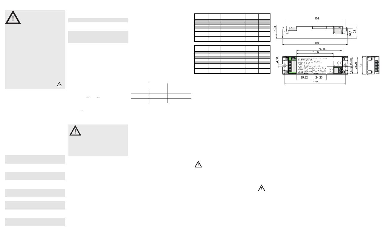
Dimensions
(L x W x H): 110 x 30 x 21mm
Average design life = 50,000 h
(ta/tc max. and a failure rate of
≤ 0.2% per 1,000h)
L‘ N: 220-240V, 50Hz
Switching threshold acc. EN 60598-2-22
Description/
Scope of application
The electronic monitoring module
V-CG-SE is suitable for operation
with electronic ballasts and incan-
descent lamps in combination with
a CEAG safety lighting system with
single luminaire monitoring in DC-
operation (Cewa-Guard-technology)
or AC-operation (S+ technology) for
programmable switching in the final
circuit (STAR-technology).
Not suitable for final circuits without
STAR-technology.
Installation
For the mounting and
operation of electrical apparatus, the
respective national safety regulations
as well as the general rules of engi-
neering will have to be observed.
Mounting
The location of mounting has to be in
accordance with the respective instruc-
tions of the luminaire manufacturer.
Inadmissible temperatures during op-
eration at the mounting location must
be observed!
Statements regarding electromagnetic
compatibility for a built-in situation are
only possible with the respective lumi-
naire. Instructions of the luminaire-or
electronic ballast manufacturer must
be observed.
We recommend the following guide-
lines:
Safety
Instructions
• The module V-CG-SE shall only be
used for its intended purpose and in
undamaged and perfect condition!
• When working on the electronic
device make sure that it is discon-
nected from the voltage! Pay atten-
tion to the different power supplies
in mains or battery operation.
• Observe the national safety rules
and regulations for prevention of
accidents as well as the safety
instructions included in these oper-
ating instruction marked with
Conformity with
standards
Conforming to: EN 61 347-2-11
and EN 60 669-2-1.
Used for installation in luminaires of
emergency lighting acc. to
EN 60 598-2-22 and for connection
to safety lighting systems acc. to
DINVDE 0100-718, EN 50 172 and
DIN VDE V 0108-100-1.
Developed, manufactured and tested
acc. to ISO 9001.
Technical data
Input voltage: 220-240 V, 50/60 Hz
176 - 275 V DC
Standby power
loss (230V/50Hz): < 0.5W
Power consumption of
connected lamp: 4 - 40 0W
max. cable length
module-luminaire: 50 m
Usable into luminaires of
the insulation class 1 and 2
Degree of protection: IP20
Perm. ambient
temperature ta: -20 °C .. +60 °C
Test point
temperature tc: 75°C
Connecting Push In
terminals: 0.13...1.5 mm²
– Keep mains leads inside the luminaire
as short as possible
– Do not run mains leads adjacent to
the electronic ballast or the lamp
– Mains leads should be kept apart
from lamp leads (ideally 5-10 cm
distance)
The mains connection has to be set to
terminals L(U) and N(0), for luminaire
connections terminals A1 - A2 have to
be used (Fig 1 or 2).
A slide-switch is used for preselec-
tion of connected load. The limit for
ok/not ok depends on the setting of
the switch:
Slide- IOK în.OK
switch
ON >47mA <28mA
OFF >16mA <10mA
The limit în.OK is given as a peak current.
If the electronic ballast has a lamp fail-
ure the cut-off must be realized within
1.6 sec. The current consumption of
ballast must be sinusoidal for AT-S+
systems or must comply with DIN EN
61000-3-2, clause 7.3a.).
The connection to the light switch of
the general lighting will be done with
terminals L’ - N (Fig 1 or 2).
Addressing
Before initial operation with CEAG
safety lighting systems, the addressing
of the individual luminaires has to be
set. For this, the desired address is set
on the address switches by means of
a suitable screw driver. If the luminaire
should not be monitored the code 0/0
has to be selected.
The increased functions „switchable
operation“ and „operation mode“ will
be available only by CEAG safety light-
ing systems with STAR-technology. (for
this see the corresponding operating
instructions of the system)
We reserve the right to make
technical alterations without notice!
Maßbild / Dimensions
Funktionsweise
Das V-CG-SE besitzt einen separaten
Steuereingang (L´-N), über den die
Sicherheitsleuchte parallel zur Fern-
einschaltung (über einen STAR Befehl)
gemeinsam mit der Allgemeinbeleuch-
tung vor Ort über einen Schalter ein- /
und ausgeschaltet werden kann. Die
Ausgangsspannung an A1 – A2 wird
von der Spannungslage an L´ - N
beeinflusst. Die Energie an A1 - A2 zur
Versorgung der Sicherheitsleuchte wird
jedoch immer nur aus der CEAG Si-
cherheitsbeleuchtungsanlage bezogen.
Achtung:
Nur für Anlagen / Stromkreisabgänge
mit STAR – Technologie geeignet!!!
Das Modul kann in zwei Modi betrie-
ben werden:
A = L´ - N (positive Logik)
Anschluss gem. Bild 1.
Adressbereich A = L´ - N an der Zeh-
nerstelle gem. Bild 3 verwenden.
A ≠ L´ - N (invertierte Logik)
Anschluss gem. Bild 2.
Adressbereich A ≠ L´ - N an der Zeh-
nerstelle gem. Bild 4 verwenden.
Programmierung an einer Anlage
mit STAR – Technologie:
– Stromkreis auf „per Leuchten-
setup“ programmieren.
– Eingestellte Adresse des V-CG-SE
im Leuchtensetup auf Bereitschaft-
slicht programmieren.
Mode of operation
The V-CG-SE contains a separate con-
trol input (L´/ N) for common switching
of the mains and the safety lighting with
a switch on location parallel to a remote
switching (via STAR command).
The output voltage at A1 – A2 will be set
depending to the voltage mode at L´ - N.
The energy of A1 – A2 is only
generated by the CEAG system.
Attention:
Only for systems / switching over units
with STAR – Technology suitable!!!
The module can be used in two modes.
A = L´ - N (positive logic)
Connection according Fig. 1
Use the tens at the address range
A = L´ - N acc. Fig. 3
A ≠ L´ - N (inverted logic)
Connection according Fig. 2
Use the tens at the address range
A ≠ L´ - N acc. Fig. 4
Programming at a system with
STAR– Technology:
– programme the circuit to “via lumi-
naire setup”
– programme the used address of
the V-CG-SE to “non maintained
mode” in the luminaire setup.
40071352528
Tabelle/Table 2: Funktion / Function A = L´N (positive Logik)
L (U) /N (0) Adresse /
STAR Befehl /
L´/ N A1 / A2
0 V 0 - 20 - 0 / 230V AC 0 V
230 V AC 1 - 20 AUS / OFF 0 V 0 V
230 V AC 1 - 20 AUS / OFF 230 V AC 230 V AC
230 V AC 1 - 20 EIN / ON 0 V 230 V AC
230 V AC 1 - 20 EIN / ON 230 V AC 230 V AC
230 V AC 1 - 20 Notbetrieb/Emergency 0 / 230V AC 230 V AC
220 V DC 0 - 20 - 0 / 230V AC 220 V DC
Tabelle/Table 3: Funktion / Function A ≠ L`N (invertierte Logik)
L (U) /N (0)
Address
command L´/ N A1 / A2
0 V 0 - 20 - 0 / 230V AC 0 V
230 V AC 1 - 20 AUS / OFF 0 V 230 V AC
230 V AC 1 - 20 AUS / OFF 230 V AC 0 V
230 V AC 1 - 20 EIN / ON 0 V 230 V AC
230 V AC 1 - 20 EIN / ON 230 V AC 230 V AC
230 V AC 1 - 20 Notbetrieb/Emergency 0 / 230V AC 230 V AC
220 V DC 0 - 20 - 0 / 230V AC 220 V DC
STAR Schaltbefehl der Anlage an ein V-CG-SE mit einer bestimmten Adresse
STAR command of the system to a V-CG-SE with a defined address

