Kicker KSMT25 Bedienungsanleitung
- Kategorie
- Autolautsprecher
- Typ
- Bedienungsanleitung


2English
Contents
Overview ..........................3
Specifications .............................4
Installation ........................5
Midrange & Tweeter
Adjustment .................................5
Pod Location & Wire Routing ......8
Pod Assembly Mounting .............9
Crossover & Wiring
Configuration ............................11
Warranty ........................13
Int. Warranty ...................48

3English
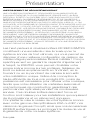
Overview
IMPORTANT SAFETY WARNING
PROLONGED CONTINUOUS OPERATION OF AN AMPLIFIER, SPEAKER, OR
SUBWOOFER IN A DISTORTED, CLIPPED OR OVER-POWERED MANNER
CAN CAUSE YOUR AUDIO SYSTEM TO OVERHEAT, POSSIBLY CATCHING
FIRE AND RESULTING IN SERIOUS DAMAGE TO YOUR COMPONENTS
AND/OR VEHICLE. AMPLIFIERS REQUIRE UP TO 4 INCHES (10CM) OPEN
VENTILATION. SUBWOOFERS SHOULD BE MOUNTED WITH AT LEAST 1
INCH (2.5CM) CLEARANCE BETWEEN THE FRONT OF THE SPEAKER AND
ANY SURFACE. KICKER PRODUCTS ARE CAPABLE OF PRODUCING SOUND
LEVELS THAT CAN PERMANENTLY DAMAGE YOUR HEARING! TURNING UP A
SYSTEM TO A LEVEL THAT HAS AUDIBLE DISTORTION IS MORE DAMAGING
TO YOUR EARS THAN LISTENING TO AN UNDISTORTED SYSTEM AT THE
SAME VOLUME LEVEL. THE THRESHOLD OF PAIN IS ALWAYS AN INDICATOR
THAT THE SOUND LEVEL IS TOO LOUD AND MAY PERMANENTLY DAMAGE
YOUR HEARING. PLEASE USE COMMON SENSE WHEN CONTROLLING
VOLUME.
The KICKER KSMT25 Dual Pod Component
speakers are an excellent upgrade to any vehicle’s
sound system, giving you an easy-to-install custom
midrange/tweeter upgrade! Designed specifically
with adjustibility in mind, the KSMT25 lets you set
your own soundstage, whether mounting to doors,
dashes, or other locations by tilting, rotating, or
leaning to accomodate your unique installation.
Like all of our KS products, they’re high-efficiency
design means less power is needed to play your
music, while our use of advanced materials and
construction techniques ensures optimal performance
for years to come. These dual pods deliver form
and function, as they’re perfect for installations that
require versatility and exacting placement. Round
out your audio upgrade with our KXA or KEY line of
amplifiers, CompR subwoofers, and genuine KICKER
accessories to extend the life and warranty of your
new system.

4English
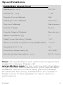
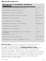
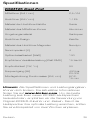
Specifications
KSMT25 Dual Pod
Midrange [in, mm] 2.5, 64
Tweeter [in, mm] 1, 25
Tweeter Dome Material Silk
Midrange Cone Material Aluminum
Surround Material Santoprene
Tweeter Design Dome
Tweeter Magnet Material Neodymium
Rated Impedance [Ω] 4
Peak Power Handling [ Watts] 100
Recommended Amplifier Power [Watts RMS] 15-50
Sensitivity [1W, 1m] 80
Frequency Response [Hz] 400-20K
Mounting Hole Diameter [in, mm] 9/16, 15mm
Note: All specifications and performance figures are
subject to change. Please visit
www.kicker.com for the most current information.
To get the best performance from your new KICKER
speakers, we recommend using genuine KICKER
accessories and wiring. Please allow two weeks of
break-in time for the speakers to reach optimum
performance.

5English
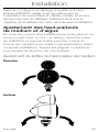
Installation
Before mounting and wiring the KSMT25 Dual Pod
component system, determine the location and
orientation of your pods, crossovers and the route of
the wiring. Disconnect the negative terminal from your
vehicle’s battery before installation.
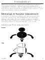
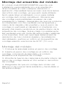
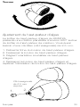
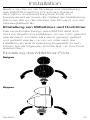
Midrange & Tweeter Adjustment
In addition to being installed just about anywhere
you can drill a hole, the KSMT25’s revolutionary
design can lean, tilt, and rotate to accomodate
any application before or after installation. Use the
following steps to directionally aim your pods.
Midrange Pod Adjustment
Lean
Tilt

6English
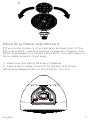
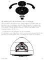
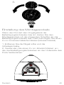
Rotate
Tweeter Pod Adjustment
The KMST25 Tweeter Pod has approximately 260° of
planetary rotation around the Midrange Pod. You will
need a 2.5mm allen wrench (hex key).
1. Remove the Tweeter Bolt Plug.
2. Loosen the Tweeter Bolt.
3. Set the desired orientation of the Tweeter Pod.
4. Retighten the Tweeter Bolt and replace the Tweeter
Bolt Plug.
1. 2.
2.5mm hex
key required

7English
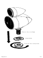
Mounting Base Adjustment
If the pod is loose on the ball and socket joint of the
Mounting Bolt, use the following steps to tighten the
Mounting Base to the Mounting Bolt. You will need a
2mm allen wrench (hex key).
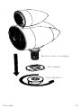
1. Remove the Wing Nut and Washer.
2. Use a 2mm allen wrench to tighten the three
Mounting Base Bolts on the bottom of pod.
3.

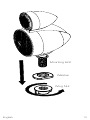
8English
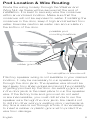
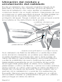
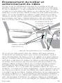
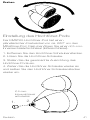
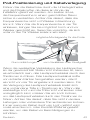
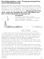
Pod Location & Wire Routing
Route the wiring loosely through the Washer and
Wing Nut, as these will be secured at the end of
installation. It is best to securely wire the crossover
within an enclosed location. Make sure that the
crossover will not be exposed to water. If installing the
crossover in the door, keep it high and shielded from
water. Exercise caution as water can accumulate in
the bottom of the door.
If factory speaker wiring is not available in your desired
location, it may be necessary to run speaker wire
through the door jamb. The speaker wire should be
kept away from sharp edges and avoid the possibility
of getting pinched by the door. An existing grommet
in the door jamb is the ideal place to run the speaker
wire. If the factory hole and grommet do not exist
or are inaccessible, you must drill a hole to run the
speaker wire through the door jamb. Be careful not
to drill into other wiring or existing door mechanisms.
Any time a wire is run through a hole, it is necessary
to insert a rubber or plastic grommet to protect the
wire from damage.
rubber grommets
from amplifier or source unit
possible pod
mounting locations

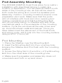
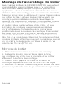
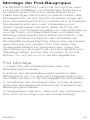
9English
Pod Assembly Mounting
The KICKER KSMT25 Dual Pods allow for a custom
installation with directional aiming in nearly any
location or application. You will need access to both
sides of the mounting hole, as this will be used to
both route the wiring and mount the speaker pod
assembly. Custom mounting locations require more
preparation and work. Make sure that the pods
will not interfere with trunk and door opening and
closing mechanisms and that the Mounting Bolt
will not puncture wiring, or interfere with any other
mechanical parts on the underside of the mounting
surface. Cycle the windows all the way down and
up. Avoid structural metal and braces. Once you
have determined the placement of the Dual Pods
and wiring route, drill a hole into the mounting surface
using a 9/16” (15mm) bit.
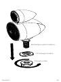
Pod Mounting
1. Place the Washer over the Mounting Bolt.
2. Insert the Mounting Bolt into the mounting hole,
bringing the Washer and Pod flush with the mounting
surface.
3. Screw the Wing Nut to the bottom of the Mounting
Bolt from the other side of the mounting hole.
4. Make sure the speaker pod assembly does not
move back and forth or up and down.

10English
Wing Nut
Washer
Mounting Bolt

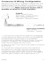
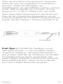
11English
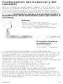
Inputs (from amplifier)
Gray - Positive
Gray/Black - Negative
Crossover & Wiring Configuration
We recommend using 16 gauge (or larger) wire. The
KSMT25 Dual Pods are rated at 4 ohms and work
with any source unit or amplifier designed to operate
at a 4 ohm load. Make sure your source unit or
amplifier is rated for 4 ohm operation.
Outputs
Black - Tweeter Positive
Black/White - Tweeter Negative
Gray - Midrange Positive
Gray/Black - Midrange Negative
1. Connect the crossover terminals and receptacles
to their respective mated connector on the KSMT25
pod assembly. The terminals on the KSMT25
crossover are all different sizes and types to prevent
incorrect connection. The crossover wire colors
match the pod assembly wire colors.
2. Slide the clear cover over the terminals to prevent a
short circuit.
3. Connect the crossover input to the outputs of
the head unit or amplifier using the supplied butt
connectors. The positive lead is the wire with gray
insulation labeled with a “plus” symbol. The negative
lead has gray insulation with a black stripe on it.

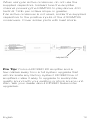
12English
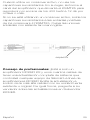
When using an active crossover, do not use the
supplied capacitors. Instead tune the amplifier
channel powering the KSMT25 to play above 400
hertz at 12db per octave slope or greater.
If an active crossover is not used, solder the supplied
capacitors to the positive inputs of the 47KSMT25
crossovers. Cover solder joints with heat shrink.
Pro Tip: You’re a KICKER KX amplifier and a
few cables away from a full system upgrade that
will dominate any factory system! KICKER line of
amplifiers make it easy to upgrade to audiophile
quality sound with your existing or stock source unit.
Also, ask your dealer about KICKER Subwoofer
upgrades.
capacitor

13English
Warranty
When purchased from an Authorized KICKER Dealer, KICKER
warrants this product to be free from defects in material and
workmanship under normal use for a period of TWO (2) YEARS from
date of original purchase with receipt. If this product is identified as
“Refurbished” or “B Goods”, the warranty is limited to a period of
THREE (3) MONTHS from the date of original purchase. In all cases
you must have the original receipt. Should service be necessary
under this warranty for any reason due to manufacturing defect
or malfunction during the warranty period, KICKER will repair or
replace (at its discretion) the defective merchandise with equivalent
merchandise. Warranty replacements may have cosmetic scratches
and blemishes. Discontinued products may be replaced with more
current equivalent products. This warranty is valid only for the original
purchaser and is not extended to owners of the product subsequent
to the original purchaser. Any applicable implied warranties are limited
in duration to a period of the express warranty as provided herein
beginning with the date of the original purchase at retail, and no
warranties, whether express or implied, shall apply to this product
thereafter. Some states do not allow limitations on implied warranties;
therefore, these exclusions may not apply to you. This warranty gives
you specific legal rights; however you may have other rights that vary
from state to state.
WHAT TO DO IF YOU NEED WARRANTY OR SERVICE:
Defective merchandise should be returned to your local Authorized
Stillwater Designs (KICKER) Dealer for warranty service. Assistance
in locating an Authorized Dealer can be found at www.KICKER.com
or by contacting Stillwater Designs directly. You can confirm that
a dealer is authorized by asking to see a current authorized dealer
window decal.
If it becomes necessary for you to return defective merchandise
directly to Stillwater Designs (KICKER), call the KICKER Customer
Service Department at (405) 624-8510 for a Return Merchandise
Authorization (RMA) number. Package only the defective items in a
package that will prevent shipping damage, and return to:
Stillwater Designs
3100 North Husband St
Stillwater, OK 74075

14English
The RMA number must be clearly marked on the outside of the
package. Please return only defective components. The return
of functioning items increases your return freight charges. Non-
defective items will be returned freight collect to you. For example,
if a subwoofer is defective, only return the defective subwoofer, not
the entire enclosure. Include a copy of the original receipt with the
purchase date clearly visible, and a “proof-of-purchase” statement
listing the Customer’s name, Dealer’s name and invoice number, and
product purchased. Warranty expiration on items without proof-of-
purchase will be determined from the type of sale and manufacturing
date code. Freight must be prepaid; items sent freight-collect, or
COD, will be refused.
WHAT IS NOT COVERED?
This warranty is valid only if the product is used for the purpose for
which it was designed. It does not cover:
o Damage due to improper installation
o Subsequent damage to other components
o Damage caused by exposure to moisture, excessive heat,
chemical cleaners, and/or UV radiation
o Damage through negligence, misuse, accident or abuse. Repeated
returns for the same damage may be considered abuse
o Any cost or expense related to the removal or reinstallation of
product
o Speakers damaged due to amplifier clipping or distortion
o Items previously repaired or modified by any unauthorized repair
facility
o Return shipping on non-defective items
o Products with tampered or missing barcode labels
o Products with tampered or missing serial numbers
o Products returned without a Return Merchandise Authorization
(RMA) number
o Products purchased from an UNAUTHORIZED dealer
o Freight Damage
o The cost of shipping product to KICKER
o Service performed by anyone other than KICKER
HOW LONG WILL IT TAKE?
KICKER strives to maintain a goal of one-week service for all
acoustics (subwoofers, midrange drivers, tweeters, crossovers, etc)
returns. Delays may be incurred if lack of replacement inventory or
parts is encountered. Failure to follow these steps may void your
warranty. Any questions can be directed to the KICKER Customer
Service Department at (405) 624-8510. Contact your International
KICKER dealer or distributor concerning specific procedures for your
country’s warranty policies.

15Español
Descripción general ........16
Especificaciones ......................17
Instalación ......................18
Ajuste de Tweeter y Midrange ...18
Ubicación del módulo
y enrutamiento del cableado .....21
Montaje del ensamble
del módulo ...............................22
Configuración del crossover
y del cableado ..........................24
Garantía | Garantie ..........48

16Español
Descripción general
ADVERTENCIA IMPORTANTE DE SEGURIDAD
LA OPERACIÓN CONTINUA Y PROLONGADA DE UN AMPLIFICADOR,
ALTAVOZ O SUBWOOFER EN UNA FORMA DISTORSIONADA, CORTADA O
CON DEMASIADA POTENCIA PUEDE RECALENTAR SU SISTEMA DE AUDIO
Y LLEGAR A INCENDIARLO, ESTO PODRÍA CAUSAR DAÑOS SERIOS A SUS
COMPONENTES Y/O VEHÍCULO. LOS AMPLIFICADORES REQUIEREN UNA
VENTILACIÓN ABIERTA DE HASTA 4PULGADAS (10CM). LOS SUBWOOFERS
DEBEN INSTALARSE CON AL MENOS 1PULGADA (2.5CM) DE ESPACIO
ENTRE LA PARTE FRONTAL DEL ALTAVOZ Y CUALQUIER SUPERFICIE. ¡LOS
PRODUCTOS KICKER TIENEN LA CAPACIDAD DE GENERAR NIVELES DE
SONIDO QUE PUEDEN DAÑAR DE FORMA PERMANENTE SU AUDICIÓN!
AUMENTAR EL VOLUMEN DE UN SISTEMA HASTA UN NIVEL QUE GENERE
DISTORSIÓN AUDIBLE ES MÁS DAÑINO PARA SUS OÍDOS QUE ESCUCHAR
UN SISTEMA SIN DISTORSIONES AL MISMO NIVEL DE VOLUMEN. EL UMBRAL
DEL DOLOR ES SIEMPRE UN INDICADOR DE QUE EL NIVEL DE SONIDO ES
DEMASIADO ELEVADO Y PUEDE DAÑAR PERMANENTEMENTE SU AUDICIÓN.
USE EL SENTIDO COMÚN CUANDO CONTROLE EL VOLUMEN.
Los altavoces del componente de módulo dual
KICKER KSMT25 son una excelente mejora para
cualquier sistema de sonido de vehículo. ¡Son
una actualización personalizada de midrange/
tweeter fácil de instalar! Con un diseño pensado
específicamente para la adaptabilidad, el KSMT25
le permite configurar su propio audio envolvente.
Puede montarlo en puertas, tableros u otros puntos;
inclinarlo, rotarlo o ladearlo para que se adapte
a su instalación particular. Como todos nuestros
productos KS, tienen un diseño de alta eficiencia
que requiere menos potencia para reproducir su
música, mientras que el uso de materiales y técnicas
de construcción avanzadas garantiza un desempeño
óptimo en los años venideros. Estos módulos duales
ofrecen forma y funcionalidad, ya que son perfectos
para instalaciones que requieren versatilidad y una
ubicación exacta. Complete su mejora de audio
con nuestra línea de amplificadores KXA o KEY,
subwoofers CompR y accesorios genuinos KICKER
para extender la vida y garantía de su nuevo sistema.

17Español
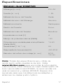
Especificaciones
Módulo dual KSMT25
Midrange [in, mm] 2,5, 64
Tweeter [in, mm] 1, 25
Material del domo del Tweeter Seda
Material del cono del Midrange Aluminio
Material envolvente Santoprene
Diseño del Tweeter Domo
Material del imán del Tweeter Neodimio
Impedancia nominal [Ω] 4
Manejo de potencia máxima [Watts] 100
Potencia recomendada para el amplificador
[Watts RMS] 15-50
Sensibilidad [1W, 1m] 80
Respuesta de frecuencia [Hz] 400-20K
Diámetro del orificio de montaje [in, mm] 9/16,
15mm
Nota: Todas las especificaciones y cifras de
rendimiento están sujetas a cambio. Visite
www.kicker.com para encontrar la información
más reciente. Para obtener el mejor desempeño de
sus nuevos altavoces KICKER, le recomendamos
usar accesorios y cables KICKER. Espere dos
semanas para que los altavoces se adapten y
alcancen su desempeño óptimo.

18Español
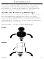
Instalación
Antes de montar y conectar el sistema de componentes
de módulo dual KSMT25, determine la ubicación
y orientación de sus módulos, crossovers y la ruta
del cableado. Antes de la instalación, desconecte la
terminal negativa de la batería de su vehículo.
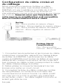
Ajuste de Tweeter y Midrange
Además de que puede ser instalado en casi cualquier
sitio donde pueda perforar un orificio, el diseño
revolucionario del KSMT25 le permite inclinar, ladear
y girar para ajustarse a cualquier aplicación antes o
después de la instalación. Siga los siguientes pasos
para orientar sus módulos.
Ajuste del módulo de Midrange
Ladee
Incline

19Español
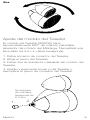
Gire
Ajuste del módulo del Tweeter
El módulo del Tweeter KMST25 tiene
aproximadamente 260° de rotación planetaria
alrededor del módulo del Midrange. Necesitará una
llave Allen de 2,5mm (llave hexagonal).
1. Retire el perno de conector del Tweeter.
2. Afloje el perno del Tweeter.
3. Determine la orientación deseada del módulo del
Tweeter.
4. Ajuste nuevamente el perno del Tweeter y
reemplace el perno de conexión del Tweeter.
1. 2.
Se requiere
de una llave
hexagonal de
2,5mm

20Español
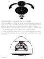
Ajuste de la base de montaje
Si el módulo no está firme en la articulación esférica
del perno de montaje, siga los siguiente pasos para
ajustar la base de montaje al perno del montaje.
Necesitará una llave Allen de 2mm (llave hexagonal).
1. Retire la tuerca de mariposa y la arandela.
2. Use una llave allen de 2mm para ajustar los tres
pernos de la base de montaje en la parte inferior del
módulo.
3.
Seite wird geladen ...
Seite wird geladen ...
Seite wird geladen ...
Seite wird geladen ...
Seite wird geladen ...
Seite wird geladen ...
Seite wird geladen ...
Seite wird geladen ...
Seite wird geladen ...
Seite wird geladen ...
Seite wird geladen ...
Seite wird geladen ...
Seite wird geladen ...
Seite wird geladen ...
Seite wird geladen ...
Seite wird geladen ...
Seite wird geladen ...
Seite wird geladen ...
Seite wird geladen ...
Seite wird geladen ...
Seite wird geladen ...
Seite wird geladen ...
Seite wird geladen ...
Seite wird geladen ...
Seite wird geladen ...
Seite wird geladen ...
Seite wird geladen ...
Seite wird geladen ...
-
 1
1
-
 2
2
-
 3
3
-
 4
4
-
 5
5
-
 6
6
-
 7
7
-
 8
8
-
 9
9
-
 10
10
-
 11
11
-
 12
12
-
 13
13
-
 14
14
-
 15
15
-
 16
16
-
 17
17
-
 18
18
-
 19
19
-
 20
20
-
 21
21
-
 22
22
-
 23
23
-
 24
24
-
 25
25
-
 26
26
-
 27
27
-
 28
28
-
 29
29
-
 30
30
-
 31
31
-
 32
32
-
 33
33
-
 34
34
-
 35
35
-
 36
36
-
 37
37
-
 38
38
-
 39
39
-
 40
40
-
 41
41
-
 42
42
-
 43
43
-
 44
44
-
 45
45
-
 46
46
-
 47
47
-
 48
48


Kicker KSMT25 Bedienungsanleitung
- Kategorie
- Autolautsprecher
- Typ
- Bedienungsanleitung
in anderen Sprachen
- English: Kicker KSMT25 Owner's manual
- français: Kicker KSMT25 Le manuel du propriétaire
- español: Kicker KSMT25 El manual del propietario
Verwandte Artikel
-
Kicker KSS269 Bedienungsanleitung
-
Kicker ST7MB ST Street Series Speakers Benutzerhandbuch
-
-
-
-
-
Kicker KS65 Benutzerhandbuch
-
Kicker DS68.2 Bedienungsanleitung
-
-