
Service
Manual
Änderungen vorbehalten Printed in Germany Service Manual Sach-Nr.
Subject to alteration VK 231 0396 Service Manual Part No. 72010-748.30
MCD 36
MCD 40
Sach-Nr./Part No.
72010-748.30
Service
Manual
Sicherheit
Safety
Sach-Nr./Part No.
72010-800.00
Zusätzlich erforder-
liche Unterlagen
für den
Komplettservice:
Additionally
required Service
Manuals for the
Complete Service:
SERVICE MANUAL
MCD 36
MCD 40
MCD 36 (9.18335-8151 / G.HF 2800)
MCD 40 (75.1118-1051 / G.HF 2900)
(9.18337-8151 / G.HF 0400)

Allgemeiner Teil / General Section MCD 36 / MCD 40
1 - 2 GRUNDIG Service
Es gelten die Vorschriften und Sicherheitshin-
weise gemäß dem Service Manual "Sicherheit",
Sach-Nummer 72010-800.00, sowie zusätzlich
die eventuell abweichenden, landesspezifischen
Vorschriften!
The regulations and safety instructions shall be
valid as provided by the "Safety" Service Manual,
part number 72010-800.00, as well as the
respective national deviations.
k
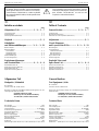
Table of Contents
Page
General Section .............................. 1 - 2 … 1 - 7
Technical Data .......................................................................... 1 - 2
Disassembly Instructions .......................................................... 1 - 3
Flowchart of Control Operation (Mechanics) ............................. 1 - 7
Adjustment ................................................... 2 - 1
Circuit Diagrams
and Layout of the PCBs .............. 3 - 1 … 3 - 12
Block Diagram........................................................................... 3 - 1
Circuit Diagrams:
CD Drive Mechanism ............................................................. 3 - 2
Main Board Part 1 .................................................................. 3 - 3
Main Board Part 2 .................................................................. 3 - 5
Layout of the PCBs .................................................................... 3 - 7
IC Block Diagrams ..................................................................... 3 - 9
Exploded Views and
Spare Parts List ............................. 4 - 1 … 4 - 4
Spare Parts List MCD 36 ........................................................... 4 - 1
Exploded View MCD 36 ............................................................. 4 - 2
Spare Parts List MCD 40 ........................................................... 4 - 3
Exploded View MCD 40 ............................................................. 4 - 4
j
Inhaltsverzeichnis
Seite
Allgemeiner Teil............................. 1 - 2 … 1 - 7
Technische Daten ..................................................................... 1 - 2
Ausbauhinweise........................................................................ 1 - 3
Steuerungsablauf (Mechanik) .................................................... 1 - 7
Abgleich ........................................................ 2 - 1
Schaltpläne
und Platinenabbildungen............ 3 - 1 … 3 - 12
Blockschaltplan .......................................................................... 3 - 1
Detailschaltpläne:
CD-Laufwerk .......................................................................... 3 - 2
Hauptplatte Teil 1 ................................................................... 3 - 3
Hauptplatte Teil 2 ................................................................... 3 - 5
Platinenabbildungen .................................................................. 3 - 7
IC Block Diagramme .................................................................. 3 - 9
Explosionszeichnungen
und Ersatzteilliste .......................... 4 - 1 … 4 - 4
Ersatzteilliste MCD 36................................................................ 4 - 1
Explosionszeichnung MCD 36 ................................................... 4 - 2
Ersatzteilliste MCD 40................................................................ 4 - 3
Explosionszeichnung MCD 40 ................................................... 4 - 4
Technische Daten
D/A-Wandler .............................................................................. 1 Bit
Oversampling-Rate ..................................................................8 fach
Frequenzbereich ............................................................20-20000Hz
Geräuschspannungsabstand .................................................... 95dB
Gleichlaufschwankung ........................................... unter Meßgrenze
Klirrfaktor (1kHz) ................................................................... 0,008%
Nenn-Ausgangspegel .............................................................. 0,68V
Nenn-Ausgangsimpedanz........................................................... 1kΩ
Stromaufnahme ..................................................................... 400mA
Betriebstemperatur .................................................. -10˚C bis +50˚C
Gewicht ca. ..................................................................................2kg
Abmessungen (MCD 36) 25 x 6,4 x 16cm, (MCD 40) 25 x 8,1 x 16cm
Technical Data
D/A Converter ............................................................................. 1Bit
Oversampling Rate ................................................................ 8 times
Frequency Range .......................................................... 20-20000Hz
Signal/Noise Ratio .................................................................... 95dB
Wow and Flutter ....................................................immeasurably low
Distortion Factor (1kHz) ........................................................ 0.008%
Nominal Output Level .............................................................. 0.68V
Nominal Output Impedance ........................................................ 1kΩ
Current Consumption ............................................................. 400mA
Operating Temperature............................................ -10˚C bis +50˚C
Weigth approx. .............................................................................2kg
Dimensions ... (MCD 36) 25 x 6.4 x 16cm, (MCD 40) 25 x 8.1 x 16cm
General Section
Test Equipment / Aids
DC-Voltmeter
Test-CD Part No. 72008-376.00
Please note the Grundig Catalog "Test and Measuring Equipment"
obtainable from:
GRUNDIG elektronics GmbH
Würzburger Str. 150, D-90766 Fürth/Bay.
Tel. 0911/703-0, Telefax 0911/703-4479
Allgemeiner Teil
Meßgeräte / Meßmittel
DC-Voltmeter
Test-CD Sachn-Nr. 72008-376.00
Beachten Sie bitte das GRUNDIG Meßtechnik-Programm, das Sie
unter folgender Adresse erhalten:
GRUNDIG elektronics GmbH
Würzburger Str. 150, D-90766 Fürth/Bay.
Tel. 0911/703-0, Telefax 0911/703-4479

MCD 36 / MCD 40 Allgemeiner Teil / General Section
GRUNDIG Service 1 - 3
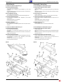
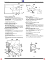
Ausbauhinweise
1. Ausbau des Gehäuses (MCD 36) Fig. 1
1a. Gehäuseoberteil abnehmen
-9 Schrauben A herausdrehen.
-4 Rastnasen 1a ausrasten und Frontblende 1 nach vorne
abziehen.
- Gehäuseoberteil an der rechten Seite ausrasten, nach links hoch-
klappen und abnehmen.
1b.Anschlußplatte ausbauen
-2 Schrauben B herausdrehen.
-Anschlußplatte C abnehmen und Steckverbindung D lösen.
1c. Gehäuseunterteil abnehmen
-4 Klebestreifen 8 abziehen und 4 Dämpfer 7 nach außen
herausziehen.
-Feder 5 und Feder 6 aushängen.
-Gehäuseunterteil abnehmen.
1d.Hebel 4 ausbauen
-2 Schrauben E herausdrehen.
- Die Hebel 4 bis zur Aussparung drehen und nach außen heraus-
nehmen.
1. Ausbau des Gehäuses (MCD 40) Fig. 1a
1a. Gehäuseoberteil abnehmen
-6 Schrauben A herausdrehen.
-Frontblende 1 ausrasten (8 Rastnasen 1a) und nach vorne
abziehen.
- Gehäuseoberteil an der rechten Seite ausrasten, nach links hoch-
klappen und abnehmen.
1b.Gehäuseunterteil abnehmen
- 2 Schrauben B herausdrehen und Anschlußplatte C abnehmen.
-4 Klebestreifen 8 abziehen und 4 Dämpfer 7 nach außen
herausziehen.
-2 Federn 5 und 2 Federn 6 aushängen.
-Gehäuseunterteil abnehmen.
Disassembly Instructions
1. Disassembling the Cabinet (MCD 36) Fig. 1
1a. Removing the Upper Part of the Cabinet
-Undo 9 screws A.
-Disengage 4 catches 1a and pull the front panel 1 towards the
front.
-Detach the top of the cabinet on the right side and raise it towards
the left to remove it.
1b.Removing the Connection PCB
-Undo 2 screws B.
-Remove the connection PCB C and unplug the connector D.
1c. Removing the Bottom Part of the Cabinet
-Remove the 4 pieces of adhesive tape 8 and pull out the 4
dampers 7.
-Unhook the spring 5 and the spring 6.
-Remove the bottom part of the cabinet.
1d.Removing the Levers 4
-Undo 2 screws E.
-Turn the levers 4 to the cutout and withdraw them.
1. Disassembling the Cabinet (MCD 40) Fig. 1a
1a. Removing the Upper Part of the Cabinet
-Undo 6 screws A.
-Disengage the front panel 1 (8 catches 1a) and pull it towards the
front.
-Detach the top of the cabinet on the right side and raise it towards
the left to remove it.
1b.Removing the Bottom Part of the Cabinet
-Undo 2 screws B and remove the connection PCB C.
-Remove the 4 pieces of adhesive tape 8 and pull out the 4
dampers 7.
-Unhook the 2 springs 5 and the 2 springs 6.
-Remove the bottom part of the cabinet.
Fig. 1
8
5
6
B
C
A
A
A
7
8
5
6
a
1
a
Fig. 1a
MCD 40MCD 36
8
8
A
A
A
B
C
D
E
7
7
6
5
4
4
a
1
a
1
E
8
7
1
1
7
1
a
1
8
7
a
1

Allgemeiner Teil / General Section MCD 36 / MCD 40
1 - 4 GRUNDIG Service
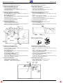
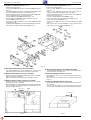
Die folgenden Ausbauhinweise beziehen sich auf das Gerät MCD 40
(für MCD 36 mit geringfügigen Abweichungen).
2. Ausbau der Hauptplatte "Main PCB"
-Gehäuseoberteil abnehmen (Pkt. 1a).
-4 Schrauben C11 herausdrehen (Fig. 2).
-Steckverbindungen D, F, G und H lösen (Fig. 2 und 4).
-Leiterplatte entnehmen.
3. Ausbau der Zahnräder C2, C3 und C4
-Hauptplatte "Main PCB" ausbauen (Pkt. 2).
-Schrauben C136 (2 Schrauben bei MCD 36, 4 Schrauben bei
MCD 40, Fig. 3) herausdrehen.
-Blende C134 abnehmen.
-4 Schrauben C10 herausdrehen und Magazinschachtoberteil C1
herausnehmen (Fig. 2).
-Kunststoffscheiben C5 und C6 (Fig. 2) abziehen.
-Zahnräder C2, C3 und C4 abziehen.
4. Ausbau des Lift-Motors C7
-Gehäuseoberteil abnehmen (Pkt. 1a).
-2 Schrauben C8 herausdrehen (Fig. 2).
-Lift-Motor C7 ablöten und herausnehmen. (Beim Einbau des
Motors auf die richtige Polung achten!)
The fellowing disassembly instructions refer to the MCD 40
(and with slight differences to MCD 36).
2. Removing the "Main PCB"
-Remove the upper part of the cabinet (para 1a).
-Undo the 4 screws C11 (Fig. 2).
-Unplug the connectors D, F, G and H (Fig. 2 and 4).
-Take out the printed circuit board.
3. Removing the Gearwheels C2, C3 and C4
-Remove the "Main PCB" (para 2).
-Undo the screws C136 (MCD 36: 2 screws, MCD 40: 4 screws,
Fig. 3).
-Remove the mechanical panel C134.
-Undo 4 screws C10 and remove the cover plate of the CD
magazine compartment C1 (Fig. 2).
-Loosen and remove the plastic washers C5 and C6 (Fig. 2).
-Pull off the gearwheels C2, C3 and C4.
4. Removing the Lift Motor C7
-Remove the upper part of the cabinet (para 1a).
-Undo 2 screws C8 (Fig. 2).
- Unsolder the lift motor C7 and take it out. (Note the correct polarity
when reassembling the motor!)
Fig. 5
I
LOADING
MOTOR
J
SLIDE LEVER
5. Ausbau des Loading-Motors C48
-Gehäuseoberteil abnehmen (Pkt. 1a).
-Schrauben C136 (2 Schrauben bei MCD 36, 4 Schrauben bei
MCD 40, Fig. 3) herausdrehen.
-Blende C134 abnehmen.
-4 Schrauben C10 herausdrehen und Magazinschachtoberteil C1
herausnehmen (Fig. 2).
-Kunststoffscheiben C53 (Fig. 5) abziehen.
-Zahnräder C51 und C50 abziehen.
-2 Schrauben C49 herausdrehen (Fig. 5).
-Loading-Motor C48 ablöten und herausnehmen. (Beim Einbau des
Motors auf die richtige Polung achten!)
6. Ausbau des Optokopplers
-Gehäuseoberteil abnehmen (Pkt. 1a).
-2 Schrauben I herausdrehen (Fig. 5).
-Optokoppler J ablöten und herausnehmen.
5. Removing the Loading Motor C48
-Remove the upper part of the cabinet (para 1a).
-Undo the screws C136 (MCD 36: 2 screws, MCD 40: 4 screws,
Fig. 3).
-Remove the mechanical panel C134.
-Undo 4 screws C10 and remove the cover plate of the CD
magazine compartment C1 (Fig. 2).
-Loosen and remove the plastic washers C53 (Fig. 5).
-Pull off the gearwheels C51 and C50.
-Undo 2 screws C49 (Fig. 5).
-Unsolder the loading motor C48 and take it out. (Note the correct
polarity when reassembling the motor!)
6. Removing the Optocoupler
-Remove the upper part of the cabinet (para 1a).
-Undo 2 screws I (Fig. 5).
-Unsolder the optocoupler J and take it out.
Fig. 2
Fig. 4
Fig. 3
1
2
Öffnen des Flexprint-Steckers
Opening the Flexprint Connector
D
F
G
H
LIFT MOTOR
FLEXPRINT

MCD 36 / MCD 40 Allgemeiner Teil / General Section
GRUNDIG Service 1 - 5
Fig. 6 Fig. 7
7. Ausbau der Leiterplatte "CD-PCB"
-Gehäuse ausbauen (Pkt. 1)
-2 Schrauben C72 und Schraube C73 herausdrehen (Fig. 6).
-
Wichtig
: Bevor die Steckverbindungen gelöst werden, müssen
die beiden Lötstellen P (Fig. 7) auf der Flexprintleitung C99
verbunden werden.
-Steckverbindungen H, K, L, M und N lösen (Fig. 4 und 6).
-Leitungen vom Disc-Motor ablöten O.
-Leiterplatte "CD-PCB" herausnehmen.
8. Ausbau der Lasereinheit C87 (Fig. 7 und 8)
-Leiterplatte "CD-PCB" ausbauen (Pkt. 7).
-4 Schrauben C93 herausdrehen (Fig. 8).
-Die Spurstangen C89 und C90 zusammen mit der Lasereinheit
C87 vorsichtig herausnehmen.
-
Wichtig
: Bevor die Steckverbindung Q der Flexprintleitung
C99 gelöst wird, müssen die beiden Lötstellen R (Fig. 7) auf
der Lasereinheit C87 verbunden werden.
9. Ausbau des Disc-Motors C76 (Fig. 2, 8 und 9)
-Lasereinheit ausbauen (Pkt. 8).
-4 Schrauben C10 herausdrehen und Magazinschachtoberteil C1
herausnehmen (Fig. 2).
-Schraube C79 herausdrehen und Schalter C78 abnehmen (Fig. 8).
-Schraube C95 herausdrehen.
-Halter C92 und Haltefeder C94 abnehmen.
-Spindel C88 herausnehmen.
-Schraube C75 herausdrehen.
-Kunststoffscheibe C86 abziehen.
-Motorhalter C74 mit Disc-Motor C76 (Fig. 9) vorsichtig herausneh-
men.
-2 Schrauben C77 (Fig. 9) herausdrehen, Motor C76 ablöten und
herausnehmen. (Beim Einbau des Motors auf die richtige Polung
achten!)
7. Removing the "CD-PCB"
-Remove the cabinet (para 1)
-Undo 2 screws C72 and the screw C73 (Fig. 6).
-
Important
: Before opening the connectors connect the two
solder tags P on the flexprint C99 as shown in Fig. 7.
-Disconnect the connectors H, K, L, M and N (Fig. 4 and 6).
-Unsolder the leads from the disc motor O .
-Take out the "CD-PCB".
8. Removing the Laser Pick-up C87 (Fig. 7 and 8)
-Take out the "CD-PCB" (para 7).
-Undo 4 screws C93 (Fig. 8).
-Take out the guides C89 and C90 together with the laser pick-up
C87 carefully.
-
Important
: Before opening the connector Q of the flexprint C99
connect the two solder tags R on the laser pick-up C87 as
shown in Fig. 7.
9. Removing the Disc Motor C76 (Fig. 2, 8 and 9)
-Remove the laser pick-up (para 8).
-Undo 4 screws C10 and remove the cover plate of the CD
magazine compartment C1 (Fig. 2).
-Undo the screw C79 and take off the switch C78 (Fig. 8).
-Undo the screw C95.
-Take out the holder C92 and supporting spring C94.
-Remove the spindle C88.
-Undo the screw C75.
-Loosen and remove the plastic washer C86.
-Remove the motor holder C74 with the disc motor C76 (Fig. 9)
carefully.
- Undo 2 screws C77 (Fig. 9), unsolder the motor C76 and take it out.
(When re-soldering the motor note the correct polarity!).
Fig. 8 Fig. 9
O
N
M
K
L
H
CD-PCB
Q
R
LASER PICK- UP
FLEXPRINT
P
DISC MOTOR
SPINDLE MOTOR

Allgemeiner Teil / General Section MCD 36 / MCD 40
1 - 6 GRUNDIG Service
10. Ausbau der Laufwerkmechanik (MCD 40)
-Gehäuse ausbauen (Pkt. 1).
-4 Schrauben C136 herausdrehen und Blende C134 abnehmen
(Fig. 10).
-4 Schrauben C10 herausdrehen und Magazinschachtoberteil C1
mit der Leiterplatte (Main PCB) herausnehmen (Fig. 2).
- Die Laufwerkmechanik durch Bewegen des Schiebers C15 "Slide
Lever" in Pfeilrichtung (Fig. 5) nach oben fahren.
-2 Federn C19 und Feder C137 aushängen (Fig. 10).
-3 Sicherungsscheiben C21 lösen und abnehmen (Fig. 10).
-3 Winkel C18 abnehmen. (Fig. 10)
-3 Schrauben C46 herausdrehen und vordere Halteplatte C41
abnehmen (Fig. 10).
-Laufwerkmechanik C47 (Fig. 10) mit den Zahnstangen herausneh-
men. Achten Sie dabei auf die 3 Hülsen C20 (Fig. 10).
10. Removing the Drive Mechanism (MCD 40)
-Remove the cabinet (para 1).
-Undo 4 screws C136 and remove the mechanical panel C134
(Fig. 10).
-Undo 4 screws C10 and remove the cover plate of the CD
magazine compartment C1 with the main PCB (Fig. 2).
- Raise the drive mechanism by moving the "Slide Lever" C15 in the
direction of the arrow (Fig. 5).
-Unhook 2 springs C19 and spring C137 (Fig. 10).
-Loosen and remove the 3 retaining washers C21 (Fig. 10).
-Remove the 3 brackets C18 (Fig. 10).
-Undo 3 screws C46 and remove the front holding plate C41
(Fig. 10).
-Take out the drive mechanism C47 (Fig. 10) and the toothed
racks. Take care of the 3 sleeves C20 (Fig. 10).
Fig. 10
11. Manuelles Ausfahren der CD aus dem Laufwerk
-Das Zahnrad C51 (Fig. 11) im Uhrzeigersinn bis zum Anschlag
drehen (der Disc-Einschub wird in das Magazin geschoben).
12. Magazin mit dem Hebel "Lock Lever" auswerfen
- Nur wenn sich alle CD´s im Magazin befinden, läßt es sich mit dem
Hebel "Lock Lever" auswerfen.
-Hebel (Geräteunterseite) in Pfeilrichtung betätigen (Fig. 12).
13. Magazin mit dem Schieber "Slide Lever" auswerfen
- Nur wenn sich alle CD´s im Magazin befinden, läßt es sich mit dem
Schieber "Slide Lever" auswerfen.
-Zahnrad C3 (Fig. 11) solange gegen den Uhrzeigersinn drehen bis
sich der Schieber am Anschlag (Pfeilrichtung) befindet und das
Magazin ausgeworfen wird.
Fig. 11 Fig. 12
C3
C51
SLIDE LEVER
11. Manual Ejection of the CD from the Drive Mechanism
-Turn the gearwheel C51 (Fig. 11) clockwise to the limit stop (disc
shelf is moved into the magazine).
12. Ejecting the Magazine with the "Lock Lever"
- Ejection with the "Lock Lever" is only possible when all CD's are in
the magazine.
-Move the "Lock Lever" (bottom side) in the direction of the arrow
(Fig. 12).
13. Ejecting the Magazine with the "Slide Lever"
- Ejection with the "Slide Lever" is only possible when all CD's are in
the magazine.
-Turn the gearwheel C3 (Fig. 11) anticlockwise until the "Slide
Lever" arrives at the limit stop (arrow) thus ejecting the magazine.
GERÄTEUNTERSEITE
BOTTOM SIDE
LOCK LEVER

MCD 36 / MCD 40 Allgemeiner Teil / General Section
GRUNDIG Service 1 - 7
MAG IN
ELV {
H
L
H
L
H
L
H
L
H
L
H
L
H
L
H
L
H
L
H
L
H
L
LOAD {
ELV |
LOAD |
LOADOUT
CLAMP
UPLIMIT
LOWLIMIT
DISC ON
DISC COUNT
MAG.SW
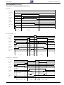
0.6sec
1.5sec
(DISC LOADING)
DISC CHANGE(DISC1 ¤2)
ELV {
H
L
H
L
H
L
H
L
H
L
H
L
H
L
H
L
H
L
H
L
H
L
LOAD {
ELV |
LOAD |
LOADOUT
CLAMP
UPLIMIT
LOWLIMIT
DISC ON
DISC COUNT
MAG.SW
1.5sec
(DISC UNLOADING)
0.2sec
(ELV DOWN)
1.5sec
(DISC LOADING)
MAG EJECT(DISC1 PLAY)
ELV {
H
L
H
L
H
L
H
L
H
L
H
L
H
L
H
L
H
L
H
L
H
L
H
L
LOAD {
ELV |
LOAD |
LOADOUT
CLAMP
UPLIMIT
LOWLIMIT
DISC ON
DISC COUNT
MAG.SW
EJECT
1.5sec
(DISC UNLOADING)
2.5sec
(ELV DOWN)
3.0sec
(ELV UP)
2sec
1101110 1
MAGAZINE IN
DISC CHANGE (DISC 1 –> 2)
Steuerungsablauf (Mechanik)
Flowchart of Control Operation (Mechanics)
MAGAZINE EJECT (DISC 1 PLAY)
ELV (LIFT) +
ELV (LIFT) –
LOAD +
LOAD –
LOAD OUT
CLAMP
UP LIMIT
LOW LIMIT
DISC ON
DISC COUNT
MAG. SW
ELV (LIFT) +
ELV (LIFT) –
LOAD +
LOAD –
LOAD OUT
CLAMP
UP LIMIT
LOW LIMIT
DISC ON
DISC COUNT
MAG. SW
ELV (LIFT) +
ELV (LIFT) –
LOAD +
LOAD –
LOAD OUT
CLAMP
UP LIMIT
LOW LIMIT
DISC ON
DISC COUNT
MAG. SW
EJECT

Abgleich / Adjustment
MCD 36 / MCD 40
2 - 2 GRUNDIG Service
2 - 1
j
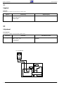
Abgleich
Meßgeräte:
Autosuper, DC-Voltmeter, Test-CD (Sach-Nr. 72008-376.00).
Tracking offset +10mV ± 3mV mit dem Regler SVR651 einstellen.DC-Voltmeter an die Meßpunkte "VR" und "TE" anschlie-
ßen (– = VR, + = TE).
Test-CD einlegen.
Funktion: PLAY
Abgleich Vorbereitung Abgleichvorgang
k
Adjustment
Test equipment:
Car Radio, DC-Voltmeter, test CD (Part No. 72008-376.00)
Adjustment Preparation Adjustment Procedure
Tracking offset Connect the DC-Voltmeter to the test points "VR" and
"TE" (– = VR, + = TE).
Load the test CD.
Function: Play
Adjust +10mV ± 3mV with the adjustment control
"SVR651".
SVR651
TE
VR
DC VOLTMETER

MCD 36 / MCD 40MCD 36 / MCD 40 Schaltpläne und Platinenabbildungen / Circuit Diagrams and Layout of PCBsSchaltpläne und Platinenabbildungen / Circuit Diagrams and Layout of PCBs
3 - 23 - 1 GRUNDIG ServiceGRUNDIG Service
Blockschaltbild / Block Diagram
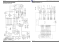
Schaltpläne und Platinenabbildungen
Circuit Diagrams and Layout of PCBs
Schaltbild / Circuit Diagram
CD-Laufwerk / CD Drive Mechanism
REGULATOR
REGULATOR
(LIFT)
CLAMP
CLAMP
SERVO
CONTROLER
FLEXPRINT
TO / FROM
3
PAGE 3 - 3 / 3 - 5
3
MAGAZIN
IC850

MCD 36 / MCD 40
3 - 4
Schaltpläne und Platinenabbildungen / Circuit Diagrams and Layout of PCBs
GRUNDIG Service
MCD 36 / MCD 40
3 - 3
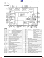
Schaltpläne und Platinenabbildungen / Circuit Diagrams and Layout of PCBs
GRUNDIG Service
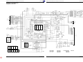
CONNECT PCB
FROM
1
PAGE 3 - 6
FROM / TO
2
PAGE 3 - 6
FROM / TO
3
PAGE 3 - 2
D910 GP1S-51V
DISC COUNT
SENSOR
(LIFT)
3
2
1
IC801
LC66358B
µ - COM
PIN
1
2
3
4
5
6
7
8
9
10
11
12
V
0
0
0
5.0
5.0
NC
5.0
5.0
5.0
5.0
5.0
4.5
PIN
13
14
15
16
17
18
19
20
21
22
23
24
V
4.0
5.0
0
0
5.0
NC
NC
5.0
5.0
0
0
5.0
PIN
25
26
27
28
29
30
31
32
33
34
35
36
V
5.0
5.0
5.0
0
0
NC
5.0
0
1.8
2.0
3.2
3.2
PIN
37
38
39
40
41
42
43
44
45
46
47
48
V
5.0
0
5.0
0
5.0
NC
NC
5.0
0
5.0
0
0
PIN
1
2
3
4
5
6
7
8
V
12
0
0
0
0
0
0
0
PIN
9
10
11
12
13
14
15
16
V
12
0
0
0
0
0
0
0
IC850
PIN
1
2
3
V
5.0
8.0
0
PIN
1
2
3
4
5
V
NC
0
0
5.0
5.0
PIN
1
2
3
4
5
V
0
4.5
0
0
5.0
PIN
1
2
3
V
8.0
0
5.0
IC501 IC551 IC802 IC803 IC804
PIN
1
2
3
V
0.5
12
5.5
B
C
E
V
0
5.0
0
B
C
E
V
4.0
0
0
B
C
E
V
11
12
12
B
C
E
V
0.5
0
0
Q550 Q801 Q802 Q803 Q804 Q805
B
C
E
V
8.6
12
8.0
B
C
E
V
4.5
1.5
5.0
BATT.
DETECT
ON
Schaltbild / Circuit Diagram (1)
Hauptplatte / Main PCB

MCD 36 / MCD 40MCD 36 / MCD 40 Schaltpläne und Platinenabbildungen / Circuit Diagrams and Layout of PCBsSchaltpläne und Platinenabbildungen / Circuit Diagrams and Layout of PCBs
3 - 63 - 5 GRUNDIG ServiceGRUNDIG Service
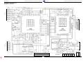
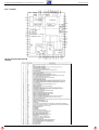
Schaltbild / Circuit Diagram (2)
Hauptplatte / Main PCB
FROM / TO
1
PAGE 3 - 4
FROM / TO
2
PAGE 3 - 4
FROM / TO
3
PAGE 3 - 2
FROM / TO
3
PAGE 3 - 2
REGULATOR
1
2
3
IC650
LA9230MS
SERVO CONTROLER
TRACKING
OFFSET
3
IC601
LC78620E
DIGITAL SIGNAL
PROCESSOR & DAC
PIN
1
2
3
4
5
6
7
8
9
10
11
12
13
14
15
16
V
2.5
2.5
2.5
2.5
2.5
2.5
2.5
2.5
2.5
2.5
2.5
2.5
2.5
2.5
2.5
2.5
PIN
17
18
19
20
21
22
23
24
25
26
27
28
29
30
31
32
V
2.5
2.5
2.5
2.5
2.5
0
2.5
2.5
2.5
2.5
2.5
2.5
2.5
2.5
2.5
0
PIN
33
34
35
36
37
38
39
40
41
42
43
44
45
46
47
48
V
0
5.0
0
5.0
0
0
0
5.0
3.0
2.5
2.5
2.5
0
NC
NC
NC
PIN
49
50
51
52
53
54
55
56
57
58
59
60
61
62
63
64
V
0
5.0
5.0
5.0
0
5.0
NC
5.0
2.5
2.5
2.5
2.5
2.0
3.8
0.2
5.0
PIN
1
2
3
4
5
6
7
8
9
10
11
12
13
14
15
16
17
18
19
20
V
0
NC
3.0
0
1.8
5.0
1.5
0
NC
5.0
2.5
NC
5.0
0
0
NC
NC
0
0
0
PIN
21
22
23
24
25
26
27
28
29
30
31
32
33
34
35
36
37
38
39
40
V
NC
NC
0
5.0
NC
NC
5.0
0
0
NC
NC
NC
NC
NC
NC
NC
NC
0
0
0
PIN
41
42
43
44
45
46
47
48
49
50
51
52
53
54
55
56
57
58
59
60
V
0
NC
NC
NC
NC
NC
5.0
5.0
5.0
0
0
5.0
5.0
5.0
NC
NC
NC
NC
NC
NC
PIN
61
62
63
64
65
66
67
68
69
70
71
72
73
74
75
76
77
78
79
80
V
0
NC
5.0
5.0
5.0
5.0
5.0
5.0
NC
NC
NC
5.0
NC
NC
0
0
0
5.0
5.0
NC
PIN 1 2 3 4 5 6 7 8 9 10 11 12 13 14
V 2.5 2.5 2.5 NC 2.5 2.5 8.0 0 8.0 0 0.5 0 0 0
PIN 15 16 17 18 19 20 21 22 23 24 25 26 27 28
V 2.0 0 0 0 0 8.0 0 0 0 NC NC 2.5 2.5 NC
IC651
PIN
1
2
3
4
5
6
7
8
V
4.0
4.0
4.0
0
3.0
3.0
4.0
8.0
PIN
1
2
3
4
5
6
7
8
V
4.0
3.0
3.0
0
4.0
4.0
4.0
8.0
IC701 IC702
B
C
E
V
8.0
12
8.0
B
C
E
V
0
0
0
B
C
E
V
0
0
0
B
C
E
V
0
2.5
2.5
Q601 Q602 Q700 Q701 Q702 Q703
B
C
E
V
3.5
2.0
4.0
B
C
E
V
0
0
0

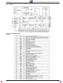
MCD 36 / MCD 40
PHOTO SENSOR
D910 (DISC COUNT)
MAGAZINE
SWITCH
UP SWITCH
LOW SWITCH
CLAMP SWITCH
SENSOR (DISC ON)
Q901
LOAD SWITCH
INSIDE SWITCH
3 - 8
Schaltpläne und Platinenabbildungen / Circuit Diagrams and Layout of PCBs
GRUNDIG Service
MCD 36 / MCD 40
3 - 7
Schaltpläne und Platinenabbildungen / Circuit Diagrams and Layout of PCBs
GRUNDIG Service
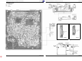
Leiterplatten / PCBs
MCD 40 MCD 36
PHOTO P.C.B.
Bestückungsseite
Component side
Lötseite
Solder side
MAIN P.C.B.
MAGAZINE SW
LOAD
MOTOR
INSIDE
1
1
1
4
3
2
1
1

MCD 36 / MCD 40 Schaltpläne und Platinenabbildungen / Circuit Diagrams and Layout of PCBs
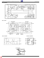
GRUNDIG Service 3 - 9
IC Blockdiagramme
IC Block Diagrams
IC601 LC78620E
CIRCUIT OPERATION DESCRIPTION
LC78620E

Schaltpläne und Platinenabbildungen / Circuit Diagrams and Layout of PCBs MCD 36 / MCD 40
3 - 10 GRUNDIG Service
IC650 LA9230MS
CIRCUIT OPERATION DESCRIPTION
LA9230MS

MCD 36 / MCD 40 Schaltpläne und Platinenabbildungen / Circuit Diagrams and Layout of PCBs
GRUNDIG Service 3 - 11
IC801 LC66358B
CIRCUIT OPERATION DESCRIPTION
LC66358B

Schaltpläne und Platinenabbildungen / Circuit Diagrams and Layout of PCBs MCD 36 / MCD 40
3 - 12 GRUNDIG Service
IC651 BA6999FB
IC803 PST9138N
IC850 LB1644
IC701/702 NJM4558M
IC802 S8054HN

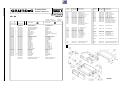
MCD 36 Explosionszeichnungen und Ersatzteilliste / Exploded Views and Spare Parts List
GRUNDIG Service 4 - 1
Ersatzteilliste
Spare Parts List
12 / 95 MCD 36
D
Btx
*
32700
#
POS. NR.
ABB.
SACHNUMMER ANZ.
POS. NO.
FIG.
PART NUMBER QUA.
BEZEICHNUNG
DESCRIPTION
D
GB
SACH-NR. / PART NO.: 9.18335-8151
BESTELL-NR. / ORDER NO.: G.HF 2800
72008-848.99 TAUSCHGERAET EXCHANGE SET
A001.000 1 75954-033.29 GEHAEUSE VORDERTEIL HOUSING
A002.000 1 75952-038.02 GEHAEUSE-OBERTEIL CABINET TOP
A003.000 1 75954-033.31 GEHAEUSE BODEN HOUSING
A004.000 1 75952-038.04 HEBEL LEVER
A005.000 1 75952-038.05 FEDER, LINKS SPRING / LEFT
A006.000 1 75952-038.06 FEDER, RECHTS SPRING / RIGHT
A007.000 1 75952-038.07 DAEMPFUNG DAMPING OR ATTENUATION
A008.000 1 75952-038.08 ABDECKUNG COVER
A009.000 1 75952-038.09 KAPPE CAP
A012.000 19772-196.00 CD-WECHSLERKABEL CD CHANGER CABLE
A015.000 75952-038.65 MAGAZIN KPL. MCD30 MAGAZINE CPL. MCD 30
C002.000 2 75952-038.16 ZAHNRAD A GEAR WHEEL A
C003.000 2 75952-038.17 ZAHNRAD B GEAR WHEEL B
C004.000 2 75952-038.18 ZAHNRAD C GEAR WHEEL C
C005.000 2 75952-038.76 SCHEIBE WASHER
C006.000 2 75952-038.77 SCHEIBE WASHER
C007.000 2 75954-033.02 MOTOR KPL. MOTOR CPL.
C031.000 2 75954-033.30 ZAHNRAD, D GEAR WHELL, D
C048.000 2 75952-038.19 MOTOR KPL. MOTOR CPL.
C050.000 2 75954-033.04 ZAHNRAD, LA GEAR WHELL, LA
C051.000 2 75954-033.05 ZAHNRAD, LB GEAR WHELL, LB
C052.000 2 75952-038.23 ZAHNRAD, G GEAR WHEEL, G
C053.000 2 75954-033.09 SPEZIAL SCHEIBE SPEZIAL WASHER
C054.000 2 75954-033.06 MOTOR KPL. MOTOR CPL.
C056.000 2 75954-033.07 ZAHNRAD, FB GEAR WHEEL, FB
C067.000 2 75953-506.06 SCHALTER SWITCH
C076.000 2 75954-033.08 MOTOR CPL. MOTOR CPL.
C078.000 2 75953-506.06 SCHALTER SWITCH
C087.000 2
S 75954-033.10 LASER EINHEIT LASER UNIT
C110.000 2 75952-038.13 ZAHNRAD, H GEAR WHEEL, H
C130.000 2 75953-506.06 SCHALTER SWITCH
72010-744.75 BEDIENUNGSANLTG.10SPR. B INSTRUCTION MANUAL B
72010-748.30 SERVICE MANUAL D/GB SERVICE MANUAL D/G
1
MCD 36
BEZEICHNUNG
DESCRIPTION
SACHNUMMER
PART NUMBER
POS. NR.
POS. NO.
BEZEICHNUNG
DESCRIPTION
SACHNUMMER
PART NUMBER
POS. NR.
POS. NO.
D 502 75952-022.06 DIODE DCC 010
D 503 75953-506.23 DIODE DCA 010
D 550 8309-701-217 Z DIODE BZX 55 B8 V2 2%
D 700 75952-041.54 Z DIODE DZD 8.2 Y
D 801 8309-720-067 Z DIODE 6,8 B 0,5W
D 802 75952-041.68 DIODE DSB 010
D 803 75952-041.68 DIODE DSB 010
D 804 75952-022.06 DIODE DCC 010
D 805 75952-041.68 DIODE DSB 010
D 806 75952-041.68 DIODE DSB 010
D 807 75952-041.68 DIODE DSB 010
D 850 75952-041.54 Z DIODE DZD 8.2 Y
D 910 75952-041.85 OPTOKOPPLER GP 1S 5V/
OPTOCOUPLER
IC 501 75952-041.45 IC S 81250 HG-RD-T2
IC 551 75952-041.50 IC L 78 M 05 T
IC 601 75954-033.17 IC LC 78620E-D
IC 650 75954-033.18 IC LA9230MS
IC 651 75954-033.19 IC BA6999FP
IC 701 75952-041.91 IC NJM 4558 M
IC 702 75952-041.91 IC NJM 4558 M
IC 801 75954-033.13 IC LC66358B-4G21
IC 802 75952-041.57 IC S 8054 HN-CB
IC 803 75954-033.15 IC PST9138N
IC 804 75952-041.79 IC TC 7 SU 04 F
IC 850 75952-041.53 IC LB 1644
Q 550 75954-033.11 TRANSISTOR 2SD2199R
Q 601 75954-033.21 TRANS. 2SA1338-5
Q 602 75952-041.74 TRANS.UN 2215
Q 700 75952-041.93 TRANS.2 SC 2812 L 6
Q 701 75952-041.42 TRANS.2 SA 1341 TA
Q 702 75952-041.74 TRANS.UN 2215
Q 703 75952-041.74 TRANS.UN 2215
Q 801 75952-041.93 TRANS.2 SC 2812 L 6
Q 802 75987-459.61 TRANS.-WIDERST.UN 2114
Q 803 75952-041.63 TRANS.DTC 124 XK
Q 804 75952-041.64 SMD-TRANS. 2SB 1202 S
Q 805 75953-501.46 SMD-TRANS. 2 SA 1179 M6
Q 901 75952-041.80 FOTO-DIODE PT 4850 F/
PHOTO DIODE PT 4850 F
RA 651 75954-033.12 RESISTOR 4X27K
SVR 651 75954-033.20 ESTR 100 KOHM
SW 1 75953-506.06 SCHALTER / SWITCH
SW 801 75952-041.59 TAKTSCHALTER /
TACT SWITCH
SW 802 75954-033.16 SCHIEBESCHALTER /
SLIDE SWITCH
SWPCB 6 75954-033.14 SCHALTER / SWITCH
TH 801 75952-041.82 NTC CS 20123 BH 102 KCTH1
X 601 75953-506.29 QUARZ 16,9344 MHZ / QUARTZ
X 801 75953-506.27 QUARZ 4,190 MHZ / QUARTZ

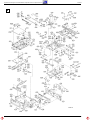
Explosionszeichnungen und Ersatzteilliste / Exploded Views and Spare Parts List
MCD 36
4 - 2 GRUNDIG Service
2
MCD 36

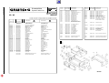
MCD 40 Explosionszeichnungen und Ersatzteilliste / Exploded Views and Spare Parts List
GRUNDIG Service 4 - 3
1
MCD 40
Ersatzteilliste
Spare Parts List
12 / 95 MCD 40
D
Btx
*
32700
#
POS. NR.
ABB.
SACHNUMMER ANZ.
POS. NO.
FIG.
PART NUMBER QUA.
BEZEICHNUNG
DESCRIPTION
D
GB
BEZEICHNUNG
DESCRIPTION
SACHNUMMER
PART NUMBER
POS. NR.
POS. NO.
BEZEICHNUNG
DESCRIPTION
SACHNUMMER
PART NUMBER
POS. NR.
POS. NO.
Q 700 75952-041.93 TRANS.2 SC 2812 L 6
Q 701 75952-041.42 TRANS.2 SA 1341 TA
Q 702 75952-041.74 TRANS.UN 2215
Q 703 75952-041.74 TRANS.UN 2215
Q 801 75952-041.93 TRANS.2 SC 2812 L 6
Q 802 75987-459.61 TRANS.-WIDERST.UN 2114
Q 803 75952-041.63 TRANS.DTC 124 XK
Q 804 75952-041.64 SMD-TRANS. 2SB 1202 S
Q 805 75953-501.46 SMD-TRANS. 2 SA 1179 M6
Q 901 75952-041.80 FOTO-DIODE PT 4850 F
PHOTO DIODE PT 4850 F
RA 651 75954-033.12 RESISTOR 4X27K
SVR 651 75954-033.20 ESTR 100 KOHM
SPCB 6 75954-033.14 SCHALTER / SWITCH
SW 801 75952-041.59 TAKTSCHALTER
TACT SWITCH
SW 802 75954-033.16 SCHIEBESCHALTER /
SLIDE SWITCH
TH 801 75952-041.82 NTC CS 20123 BH 102 KCTH1
X 601 75953-506.29 QUARZ 16,9344 MHZ / QUARTZ
X 801 75953-506.27 QUARZ 4,190 MHZ / QUARTZ
72008-849.99 TAUSCHGERAET EXCHANGE SET
A001.000 1 75954-033.22 GEHAEUSE VORDERTEIL HOUSING FRONT
A002.000 1 75954-033.23 GEHAEUSE-OBERTEIL CABINET TOP
A003.000 1 75954-033.24 GEHAEUSE BODEN HOUSING BOTTOM
A004.000 1 75954-033.25 HEBEL LEVER
A005.000 1 75954-033.26 FEDER LINKS SPRING LEFT
A006.000 1 75954-033.27 FEDER RECHTS SPRING RIGHT
A007.000 1 75952-038.07 DAEMPFUNG DAMPING OR ATTENUATION
A008.000 1 75952-038.08 ABDECKUNG COVER
A009.000 1 75954-033.28 GUMMIPUFFER CASHION RUBBER
A010.000 1 75952-038.09 KAPPE CAP
A012.000 19772-196.00 CD-WECHSLERKABEL CD CHANGER CABLE
A015.000 75954-033.01 MAGAZIN KPL. MAGAZINE CPL.
C002.000 2 75952-038.16 ZAHNRAD A GEAR WHEEL A
C003.000 2 75952-038.17 ZAHNRAD B GEAR WHEEL B
C004.000 2 75952-038.18 ZAHNRAD C GEAR WHEEL C
C005.000 2 75952-038.76 SCHEIBE WASHER
C006.000 2 75952-038.77 SCHEIBE WASHER
C007.000 2 75954-033.02 MOTOR KPL. MOTOR CPL.
C028.000 2 75954-033.03 ZAHNRAD, PLATTE GEAR WHEEL, BOARD
C039.000 2 75953-506.06 SCHALTER SWITCH
C048.000 2 75952-038.19 MOTOR KPL. MOTOR CPL.
C050.000 2 75954-033.04 ZAHNRAD, LA GEAR WHEEL, LA
C051.000 2 75954-033.05 ZAHNRAD, LB GEAR WHEEL, LB
C052.000 2 75952-038.23 ZAHNRAD, G GEAR WHEEL, G
C053.000 2 75954-033.09 SPEZIAL SCHEIBE SPECIAL WASHER
C054.000 2 75954-033.06 MOTOR KPL. MOTOR CPL.
C056.000 2 75954-033.07 ZAHNRAD, FB GEAR WHEEL, FB
C067.000 2 75953-506.06 SCHALTER SWITCH
C076.000 2 75954-033.08 MOTOR CPL. MOTOR CPL.
C078.000 2 75953-506.06 SCHALTER SWITCH
C087.000 2 S
75954-033.10 LASER EINHEIT LASER UNIT
C110.000 2 75952-038.13 ZAHNRAD H GEAR WHEEL, H
C130.000 2 75953-506.06 SCHALTER SWITCH
72010-744.80 BEDIENUNGSANLTG.10-SPR. B INSTRUCTION MANUAL B
72010-748.30 SERVICE MANUAL D/GB SERVICE MANUAL D/GB
D 502 75952-022.06 DIODE DCC 010
D 503 75953-506.23 DIODE DCA 010
D 550 8309-701-217 Z DIODE BZX 55 B8 V2 2%
D 700 75952-041.54 Z DIODE DZD 8.2 Y
D 801 8309-720-067 Z DIODE 6,8 B 0,5W
D 802 75952-041.68 DIODE DSB 010
D 803 75952-041.68 DIODE DSB 010
D 804 75952-022.06 DIODE DCC 010
D 805 75952-041.68 DIODE DSB 010
D 806 75952-041.68 DIODE DSB 010
D 807 75952-041.68 DIODE DSB 010
D 850 75952-041.54 Z DIODE DZD 8.2 Y
D 910 75952-041.85 OPTOKOPPLER GP 1S 5V/
OPTOCOUPLER GP 1S 5V
IC 501 75952-041.45 IC S 81250 HG-RD-T2
IC 551 75952-041.50 IC L 78 M 05 T
IC 601 75954-033.17 IC LC 78620E-D
IC 650 75954-033.18 IC LA9230MS
IC 651 75954-033.19 IC BA6999FP
IC 701 75952-041.91 IC NJM 4558 M
IC 702 75952-041.91 IC NJM 4558 M
IC 801 75954-033.13 IC LC66358B-4G21
IC 802 75952-041.57 IC S 8054 HN-CB
IC 803 75954-033.15 IC PST9138N
IC 804 75952-041.79 IC TC 7 SU 04 F
IC 850 75952-041.53 IC LB 1644
Q 550 75954-033.11 TRANSISTOR 2SD2199R
Q 601 75954-033.21 TRANS. 2SA1338-5
SACH-NR. / PART NO.: 9.18337-8151, BESTELL-NR. / ORDER NO.: G.HF 0400
SACH-NR. / PART NO.: 75.1118-1051, BESTELL-NR. / ORDER NO.: G.HF 2900

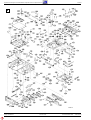
Explosionszeichnungen und Ersatzteilliste / Exploded Views and Spare Parts List
MCD 40
2
MCD 40
Änderungen vorbehalten Printed in Germany Service Manual Sach-Nr.
Subject to alteration VK 231 0396 Service Manual Part No. 72010-748.30
-
 1
1
-
 2
2
-
 3
3
-
 4
4
-
 5
5
-
 6
6
-
 7
7
-
 8
8
-
 9
9
-
 10
10
-
 11
11
-
 12
12
-
 13
13
-
 14
14
-
 15
15
-
 16
16
-
 17
17
-
 18
18
-
 19
19
-
 20
20


