
Bedienungsanleitung/
Instruction manual
eFuse 2 100-10

eFuse 2-100-10
manual efuse2-100-10_neu.docx rev03 2 Ausgabe 20.01.2017
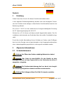
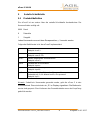
Inhaltsverzeichnis / Index
1 Einleitung ................................................................................................... 3
2 Allgemeine Informationen ........................................................................... 3
2.1 Sicherheitshinweise ............................................................................. 3
2.2 Lieferumfang ........................................................................................ 4
3 Inbetriebnahme .......................................................................................... 4
4 Bedienung .................................................................................................. 5
5 Serielle Schnittstelle ................................................................................... 6
5.1 Protokolldefinition ................................................................................ 6
6 Technische Daten ....................................................................................... 7
7 Anhang ..................................................................................................... 10
7.1 CE Konformitätserklärung .................................................................. 10
1. Introduction .............................................................................................. 12
2. General information .................................................................................. 12
2.1. Safety instructions ............................................................................. 12
2.2. Whats Included .................................................................................. 13
3. Start Up Procedure ................................................................................... 13
4. Operation ................................................................................................. 13
5. Serial interface ......................................................................................... 14
5.1. Protocol definition .............................................................................. 14
6. Technical data .......................................................................................... 16
7. Appendix .................................................................................................. 18
7.1. Declaration of conformity ................................................................... 18

eFuse 2-100-10
manual efuse2-100-10_neu.docx rev03 3 Ausgabe 20.01.2017
Deutsch
1 Einleitung
Vielen Dank, dass Sie sich für dieses Produkt entschieden haben.
In der folgenden Bedienungsanleitung werden Ihnen die wichtigsten Funktio-
nen des Gerätes sowie etwaige zu beachtende Vorsichtsmaßnahmen bei der
Bedienung erläutert.
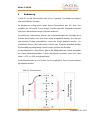
Die eFuse 2 100-10 ist eine elektronische Hochgeschwindigkeits-Sicherung
für DC Spannungseingänge bis 100 VDC.
Ströme bis zu 10 A können mit dieser schnell abgeschaltet werden. Der Ab-
schaltstrom wird entweder am Gerät oder über die serielle Schnittstelle einge-
stellt.
Durch die schnelle Abschaltung können Schäden an Probes sowie Prüflingen
durch zu hohe Energie, wie sie typischerweise in den Ausgangskondensatoren
eines Labornetzgerätes gespeichert ist, wirkungsvoll vermieden werden.
2 Allgemeine Informationen
2.1 Sicherheitshinweise
Achtung: Vor Öffnen des Gerätes unbedingt Netzstecker ziehen!
Achtung: Das Gerät ist ausschließlich für den Betrieb an einer
Netzspannung wie auf dem Typenschild an der Rückseite der eFuse 2
angegeben, ausgelegt.
Achtung: Die Geräteschutzsicherung darf nur durch eine bauglei-
che Sicherung mit gleichen elektrischen Daten ersetzt werden.
Achtung: Die Lüftungsschlitze (5 in Bild 6-1) niemals verstellen.

eFuse 2-100-10
manual efuse2-100-10_neu.docx rev03 4 Ausgabe 20.01.2017
Achtung: Die Ausgangsbuchsen nur mit Sicherheitssteckverbin-
dern anschließen. An ihnen kann lebensgefährliche Spannung anliegen.
Achtung: Gerät nur durch geschultes Personal bedienen.
Achtung: Betreiben Sie das Gerät niemals in einer explosiven Um-
gebung.
2.2 Lieferumfang
• eFuse 2 100-10
• Netzanschlusskabel
• Bedienungsanleitung eFuse 2 100-10
3 Inbetriebnahme
Der Anschluss erfolgt über das zum Lieferumfang gehörende Netzanschluss-
kabel am rückseitigen Netzeingang (7 in Bild 6-1).
Achtung: Das Gerät darf ausschließlich mit der auf dem Ty-
penschild angekreuzten Netzspannung betrieben werden!
Nach Anschluss an das Versorgungsspannungsnetz ist das Gerät sofort be-
triebsbereit.
Die Grüne LED „ON“ (2 in Bild 6-1) sollte leuchten. Es wird damit signalisiert,
dass die eFuse sich im leitenden Zustand befindet.
Die Eingangsspannung wird in diesem Zustand direkt zu den Ausgangsbuch-
sen „OUT“ (4 in Bild 6-1) und „-OUT“ (4 in Abbildung 6-1) durchgeschleift (Bild
6.1).

eFuse 2-100-10
manual efuse2-100-10_neu.docx rev03 5 Ausgabe 20.01.2017
4 Bedienung
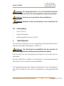
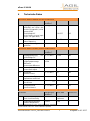
In Bild 4.1 ist die Menüstruktur der eFuse 2 gezeigt. Die Bedienung folgt ei-
nem einheitlichen Konzept.
Im Hauptmenü erfolgt durch einen kurzen Tastendruck das Ein- bzw. Aus-
schalten der Sicherung. Durch langes Drücken wird das Untermenü betreten
und durch wiederholtes langes Drücken verlassen.
Innerhalb des Untermenüs können die aufeinanderfolgenden Einträge durch
Drehen des Knopfes nach links oder rechts ausgewählt werden. Um den ent-
sprechenden Eintrag auszuwählen, muss der Knopf gedrückt werden.. An-
schließend können die Daten durch Drehen des Knopfes verändert werden.
Die Bestätigung erfolgt immer durch kurzes Drücken des Knopfes.
In dem Menüpunkt „Start Strom“ gibt es die Möglichkeit den zuletzt eingestell-
ten Strom wiederherzustellen. Dieser Menüpunkt erscheint, wenn der Start-
strom < 0.01 A > 9.99 A eingestellt wird.
Die Kalibrierfunktion ist nur für den Service zugänglich. Ihre eFuse ist werksei-
tig kalibriert worden.
Bild 4.1: Menüstruktur

eFuse 2-100-10
manual efuse2-100-10_neu.docx rev03 6 Ausgabe 20.01.2017
5 Serielle Schnittstelle
5.1 Protokolldefinition
Die eFuse2 ist von extern über die serielle-Schnittstelle fernbedienbar. Die
Kommunikation erfolgt mit:
9600 Baud
8 Datenbits
1 Stoppbit.
Jedes Kommando muss mit dem Escapezeichen „\n“ beendet werden.
Folgender Befehlssatz ist in der eFuse2 implementiert:
icurr?
Aktuell fließender Strom.
Beispiel: icurr?\n
curr
Setzt den zulässigen Maximalstrom.
Beispiel: curr\n9.12\n
scurr?
Aktuell eingestellter Maximalstrom.
Beispiel: scurr?\n
inpon
Schaltet die eFuse leitend.
Beispiel: inpon\n
inpoff
Schaltet die eFuse sperrend.
Beispiel: inpoff\n
inp?
Gibt den aktuellen Status der eFuse zurück.
Antwortet mit 1\n für leitend und 0\n für sperrend.
Beispiel: inp?\n
Hinweis: Sobald ein Kommando gesendet wurde, geht die eFuse 2 in den
Remotebetrieb. Dies wird durch ein „R“ im Display signalisiert. Die Bedienele-
mente sind gesperrt. Zum Verlassen des Remotebetriebs muss der Knopf lang
gedrückt werden.

eFuse 2-100-10
manual efuse2-100-10_neu.docx rev03 7 Ausgabe 20.01.2017
6 Technische Daten
Technische Daten Eingang/ Technical Data Input
Parameter
Bedingungen/
conditions
Wert/ data
Einheit/ unit
V
i
Eingangsspannung AC/
werkseitig auf einen der
Bereiche eingestellt.( siehe
Typenschild)I
Input Voltage AC
Set by factory to one input
range ( see type label)
0°C<T
a
<40°C
207-253
98-127
VAC
VAC
f
Netzfrequenz/
mains frequency
47...63
Hz
F
in
Eingangssicherung/
Input fuse
100
mA/T
Technische Daten Schalter/ Technical Data Switch
Parameter
Bedingungen/
conditions
Wert/ data
Einheit/ unit
V
i
Eingangsspannung DC
Input Voltage DC
0°C<T
a
<40°C
0-100
VDC
ΔV
i
Eingangs-
Ausgangsspannungs-
differerenz
Input-output difference
0°C<T
a
<40°C
I
a
=10A
500
mVDC
I
limit
Grenzstromeinstellung
Current limit adjust
0°C<T
a
<40°C
0-10
ADC
I
nom
Nennstrom
nominal current
0°C<T
a
<40°C
10
ADC
T
k
Temperaturkoeffizient/
temperature coefficient
0.03
%/K
t
sw
Abschaltzeit
turn-off-time
90%- 10% I
nom
<300
ns
R
i
Innenwiderstand
Inner Resistance
0°C<T
a
<40°C
50
mΩ
Technische Daten Allgemein/ Technical Data Switch
Parameter
Bedingungen/
conditions
Wert/ data
Einheit/ unit
Kurzschlussfestigkeit
Short circuit Immunity
0°C<T
a
<40°C
dauernd
continous
VDC
Umgebungstemperatur
Ambient temperature
I
load
=I
nom
0-40
°C
Technische Daten bei Ta = 25°C wenn nicht anders angegeben
Technical Data at Ta= 25°C unless otherwise specified

eFuse 2-100-10
manual efuse2-100-10_neu.docx rev03 8 Ausgabe 20.01.2017

eFuse 2-100-10
manual efuse2-100-10_neu.docx rev03 9 Ausgabe 20.01.2017
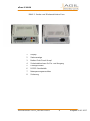
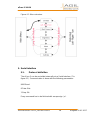
Bild 6.1: Vorder- und Rückansicht der eFuse
1
Display
2
Statusanzeige
3
Bedien-Dreh-Druck-Knopf
4
Sicherheitsbuchsen für Ein- und Ausgang
5
Lüftungsschlitze
6
RS232-Schnittstelle
7
Netzspannungsanschluss
8
Sicherung

eFuse 2-100-10
manual efuse2-100-10_neu.docx rev03 10 Ausgabe 20.01.2017
7 Anhang
7.1 CE Konformitätserklärung
CE Konformitätserklärung
Der Hersteller
AGIL-Elektronik GmbH
Wittestr. 49
D-13509 Berlin
erklärt hiermit dass das nachstehende Gerät
eFuse2-100-10
Übereinstimmt mit den nachfolgenden Richtlinien
Niederspannungsrichtlinie 2014/35/EU
EMV Richtlinie 2014/30/EU
Angewandte technische Normen
EN61010-1 2011-07
EN 61326-1 :2013
Berlin 20.04.2016
-------------------------------------
Ort Datum
Dipl. Ing. A. v. Müller Geschäftsführer AGIL-Elektronik GmbH
------------------------------------------------------------------------------------
Name Position
-------------------------------------------------
Unterschrift

eFuse 2-100-10
manual efuse2-100-10_neu.docx rev03 11 Ausgabe 20.01.2017

eFuse 2-100-10
manual efuse2-100-10_neu.docx rev03 12 Ausgabe 20.01.2017
English
1. Introduction
Firstly, we would to thank you for choosing our product.
Included in the following instruction manual are the key features of the product
as well as the safety precautions that should be considered when the unit is in
use.
The eFuse 2 100-10 is an electronic high-speed-fuse for DC voltage input up
to 100VDC.
Currents up to 10 Amps can be switched off by this device. The maximum
current before switch off can be adjusted either with the device directly or by
adjustment with a serial interface.
The quick cut-off feature of this product prevents damages on Probes as well
as devices under test by high energies, typically stored in the output
capacitors of laboratory DC- supplies.
2. General information
2.1. Safety instructions
Attention: Before opening the unit always unplug from the mains
power supply.
Attention: The unit is only designed for mains voltage as
indicated on the label to rear of the eFuse 2 unit.
Attention: The mains fuse (8) in figure 6-1 has to be replaced
with a fuse of same kind and same electrical properties.
Attention: Never cover the ventilation slots in the housing case
of eFuse 2.
Attention: Always connect the In and Output jacks with correctly
manufactured plugs that meet safety standards. There could be life
threatening voltages at the In- and Output jacks!
Attention: The use of the unit shall only be done by trained
personnel.

eFuse 2-100-10
manual efuse2-100-10_neu.docx rev03 13 Ausgabe 20.01.2017
Attention: Do not use the unit in an explosive environment!
2.2. Whats Included
efuse 2 100-10
Mains plug connector
Instruction manual for eFuse 2 100-10
3. Start Up Procedure
Connect the mains supply cable with the mains Input connector ( 7 in figure
6.1) at rear of eFuse 2.
Attention: The device should only be operated with Mains
Voltage as indicated on the label!
After connecting the mains supply to eFuse 2 the unit is ready for use.
The green LED “On” should be lit. This shows that eFuse 2 is in a
conducting state.
The input voltage is looped directly through to the Output jacks “OUT” and
“-OUT” (4 in figure 6.1).
4. Operation
The menu structure of eFuse 2 is shown in figure 4.1. The operating of
eFuse is realized with a unit concept.
In the main menu the on- off switching of eFuse 2 takes place by a short
push of the multi-function knob (3 in figure 6.1). By holding the button for
longer the second level of menu will be displayed and after holding the
button for longer again the second level of the menu will be left.
Within the second level of the menu the different sections of the menu can
be chosen by turning the knob one position left or right. To enter the
chosen menu hold the knob for a short while. Then data can be changed
by turning the knob. The confirmation of the changed data is done by
pushing the knob.
At the menu entry “ Start Strom” there is the option to save a value for the
programmed ‘Switch Off Current’ the eFuse 2 will remember when started
again after being disconnected from the mains supply e.g. the eFuse was
switched off.
The calibration menu is only available for service. Calibration is factory set.

eFuse 2-100-10
manual efuse2-100-10_neu.docx rev03 14 Ausgabe 20.01.2017
Figure 4-1: Menu structure
5. Serial interface
5.1. Protocol definition
The eFuse 2 can be controlled externally via a Serial Interface (7 in
figure 6.1). Communication is done with the following parameters:
9600 Baud
8 Data- Bits
1 Stop- Bit
Every command has to be finished with escape sign „\n“.

eFuse 2-100-10
manual efuse2-100-10_neu.docx rev03 15 Ausgabe 20.01.2017
The following instructions are implemented in eFuse 2:
icurr?
Gives back actual flowing current.
Example: icurr?\n
curr
Sets the possible maximum current.
Example: curr\n9.12\n
scurr?
Gives back actual set maximum current
Example: scurr? \n
inpon
Switches the eFuse 2 on.
Example: inpon\n
inpoff
Switches the eFuse 2 off.
Example: inpoff\n
inp?
Gives back the actual state of eFuse.
Answers with 1\n for on state and 0\n for off state
Example: inp? \n
Hint: As soon as a command is sent, the eFuse 2 switches to remote
operation. This is announced by an „R“ in the display. The operating
switches on front of the eFuse 2 unit are locked but to leave the remote
mode please hold the multifunction knob for a while.

eFuse 2-100-10
manual efuse2-100-10_neu.docx rev03 16 Ausgabe 20.01.2017
6. Technical data
Technische Daten Eingang/ Technical Data Input
Parameter
Bedingungen/
conditions
Wert/ data
Einheit/ unit
V
i
Eingangsspannung AC/
werkseitig auf einen der
Bereiche eingestellt.( siehe
Typenschild)
Input Voltage AC
Set by factory to one input
range ( see type label)
0°C<T
a
<40°C
207-253
98-127
VAC
VAC
f
Netzfrequenz/ mains
frequency
47...63
Hz
F
in
Eingangssicherung/
Input fuse
100
mA/T
Technische Daten Schalter/ Technical Data Switch
Parameter
Bedingungen/
conditions
Wert/ data
Einheit/ unit
V
i
Eingangsspannung DC
Input Voltage DC
0°C<T
a
<40°C
0-100
VDC
ΔV
i
Eingangs-
Ausgangsspannungs-
differerenz
Input-output difference
0°C<T
a
<40°C
I
a
=10A
500
mVDC
I
limit
Grenzstromeinstellung
Current limit adjust
0°C<T
a
<40°C
0-10
ADC
I
nom
Nennstrom
nominal current
0°C<T
a
<40°C
10
ADC
T
k
Temperaturkoeffizient/
temperature coefficient
0.03
%/K
t
sw
Abschaltzeit
turn-off-time
90%- 10% I
nom
<300
ns
R
i
Innenwiderstand
Inner Resistance
0°C<T
a
<40°C
50
mΩ
Technische Daten Allgemein/ Technical Data common
Parameter
Bedingungen/
conditions
Wert/ data
Einheit/ unit
Kurzschlussfestigkeit
Short circuit Immunity
0°C<T
a
<40°C
dauernd
continous
VDC
Umgebungstemperatur
Ambient temperature
I
load
=I
nom
0-40
°C
Technische Daten bei Ta = 25°C wenn nicht anders angegeben
Technical Data at Ta= 25°C unless otherwise specified

eFuse 2-100-10
manual efuse2-100-10_neu.docx rev03 17 Ausgabe 20.01.2017
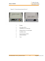
Figure 6-1: Front and rear view of eFuse 2
1
Display
2
Unit status LEDs
3
Operating Turn-Push knob
4
Safety jacks for In- and Output
5
Ventilation slots
6
Serial interface RS232
7
Mains connector
8
Fuse

eFuse 2-100-10
manual efuse2-100-10_neu.docx rev03 18 Ausgabe 20.01.2017
7. Appendix
7.1. Declaration of conformity
CE – Declaration of conformity
The manufacturer
AGIL-Elektronik GmbH
Wittestr. 49
D-13509 Berlin
hereby declares the following device
eFuse2-100-10
conforms with the following directives
Low- voltage directive 2014/35/EU
EMV directive 2014/30/EU
Applied technical standards
EN61010-1 2011-07
EN 61326-1 :2013
Berlin 20.04.2016
-------------------------------------
Place Date
Dipl. Ing. A. v. Müller Managing Director AGIL-Elektronik GmbH
------------------------------------------------------------------------------------
Name Position
-------------------------------------------------
Signature

eFuse 2-100-10
manual efuse2-100-10_neu.docx rev03 19 Ausgabe 20.01.2017

eFuse 2-100-10
manual efuse2-100-10_neu.docx rev03 20 Ausgabe 20.01.2017
AGIL-Elektronik GmbH
Wittestr. 49
13509 Berlin
www.agil-elektronik.de
-
 1
1
-
 2
2
-
 3
3
-
 4
4
-
 5
5
-
 6
6
-
 7
7
-
 8
8
-
 9
9
-
 10
10
-
 11
11
-
 12
12
-
 13
13
-
 14
14
-
 15
15
-
 16
16
-
 17
17
-
 18
18
-
 19
19
-
 20
20


Agil Elektronik eFuse 2 100-10 Benutzerhandbuch
- Typ
- Benutzerhandbuch
- Dieses Handbuch eignet sich auch für
in anderen Sprachen
Andere Dokumente
-
Trebs 99387 Benutzerhandbuch
-
HP t240 Thin Client Benutzerhandbuch
-
STIEBEL ELTRON SHU 10 SLI COMFORT Bedienungsanleitung
-
Yamaha QY22 Benutzerhandbuch
-
Hama 1T014160 Operating Instructions Manual
-
LG 24MB65PY-I Datenblatt
-
EINHELL GC-BC 30 AS Product Sheet
-
Parkside PDWS 125 A1 Translation Of The Original Instructions
-
EINHELL TE-RS 18 Li-Solo Product Sheet