Konigshutte Virgo 28/865 Benutzerhandbuch
- Kategorie
- Öfen
- Typ
- Benutzerhandbuch

GB
D
F
NL
E
Anleitung Seite 2 - 9
Instruction Page 10 - 17
Instructions Page 18 - 25
Aanwijzing Pagina 26 - 33
Manual de instrucciones Página 34 - 41
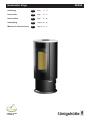
Kaminofen Virgo 28/865
- DIN EN 13240
- 15a BV-G

2
Vorwort
Dieser Kaminofen ist ein Spitzenprodukt moderner
Heiztechnik.
Großer Bedienungskomfort und hohe Brenn stoff-
aus nutzung gestatten den Einsatz als hochwertige
Raumheizung, ohne auf die angenehme Atmosphäre
eines Kaminfeuers verzichten zu müssen.
Ordnungsgemäße Aufstellung sowie richtige Hand-
habung und Pege sind für einen störungsfreien
Betrieb und lange Lebensdauer unerlässlich. Beachten
Sie deshalb alle Hinweise in dieser Anleitung. Wir sind
überzeugt, dass Ihnen dieser Kaminofen dann viel
Freude bereiten wird. Bewahren Sie diese Anleitung
gut auf, damit Sie sich bei Beginn der Heizperiode im-
mer wieder über die richtige Bedienung informieren
können.
Transportschäden sind umgehend (innerhalb von 2 Ta-
gen) an Ihren Lieferanten zu melden.
Inhaltsübersicht
Vorwort ...................................................................... 2
Technische Daten ..................................................... 3
Zu beachtende Vorschriften .................................... 3
Schornsteinbemessung ........................................... 3
Verbrennungsluftversorgung .................................. 3
Externer Verbrennungsluftanschluss .......................... 3
Aufstellen des Kaminofens ..................................... 4
Kaminofen drehbar ..................................................... 4
Mindestabstand
zu brennbaren oder tragenden Wänden..................... 4
Montagefolge ............................................................. 5
Bedienung ................................................................. 6
Zulässige Brennstoffe ................................................. 6
Beachten Sie vor dem ersten Heizen ......................... 6
Anzünden ................................................................... 6
Luftsteller .................................................................... 7
Einstellen der Verbrennungsluft.................................. 7
Heizen ........................................................................ 8
Heizen während der Übergangszeit ........................... 8
Verkleidung ............................................................... 8
Besondere Hinweise ................................................ 8
Reinigung .................................................................. 8
Ersatzteile.................................................................. 9
Was ist, wenn …? ..................................................... 9
Sachmängelhaftung ................................................. 9

3
Technische Daten
● Nennwärmeleistung ....................................... 5,5 kW
● Höhe bis Mitte Anschlussstutzen
bei Anschluss hinten 1) ................................ 933 mm
● Höhe bis Oberkante Anschlussstutzen
bei Anschluss oben ....................................1128 mm
● Anschlussstutzen Ofenrohr ..................... Ø 150 mm
● max. Gewicht (Natursteinverkleidung) .......... 155 kg
● max. Gewicht (Keramikverkleidung) .............. 140 kg
● max. Gewicht (Stahlverkleidung) ................... 140 kg
● Höhe bis Mitte Verbrennungsluftstutzen ...... 180 mm
● Anschlussstutzen Verbrennungsluft ........ Ø 125 mm
● Betriebsart ................................................. Zeitbrand
1)
Bei Anschluss hinten ist das Gerät nicht mehr drehbar.
Zu beachtende Vorschriften
● Örtliche und baurechtliche Vorschriften
● Der Kaminofen ist von einem Fachmann aufzu-
stellen und an den Schornstein anzuschließen.
Die länderspezischen Vorschriften sind zur siche-
ren Installation des Verbindungsstückes zu beach-
ten. Das verwendete Verbindungsstück muss eine
Reinigungsöffnung besitzen.
● Eine regelmäßige Überprüfung des Kaminofens ist
von einem Fachmann durchzuführen.
Der Kaminofen besitzt eine Feuerraumtür die selbsttä-
tig schließt, somit ist er zugelassen für den An schluss
an mehrfach belegte Schornsteine.
Schornsteinbemessung
Die Schornsteinbemessung erfolgt nach
DIN EN 13384 - 2 bzw. nach den länderspezischen
Vorschriften. Der Schornstein muss der Temperatur-
klasse T400 entsprechen.
Erforderliche Daten
Geschlossener Betrieb:
● Nennwärmeleistung ....................................... 5,5 kW
● Abgasmassenstrom ....................................... 5,3 g/s
● Abgastemperatur ........................................... 277 °C
● Mindestförderdruck bei Nennwärmeleistung ...12 Pa
Verbrennungsluftversorgung
Es ist sicherzustellen, dass dem Kaminofen ausrei-
chend Verbrennungsluft zur Verfügung steht. Für eine
einwandfreie Funktion des Kaminofens ist ein notwen-
diger Verbrennungsluftvolumenstrom von 15,6 m³/h zu
berücksichtigen.
Externer Verbrennungsluftanschluss
Die Verbrennungsluft kann bei externer Be triebsweise
von außen über eine dichte Leitung oder über ein LAS-
System zugeführt werden. Sprechen Sie deshalb mit
Ihrem Bezirksschornsteinfegermeister.
Aus Energiespargründen (EnEV) sollte bei Nichtbetrieb
des Kaminofens die Verbrennungsluftzuhr absperrbar
sein. Dies kann durch eine Absperrklappe in der Ver-
bren nungsluftleitung oder durch die Luftschieber
am Kaminofen geschehen. Bei Einsatz einer
Absperrklappe, muss diese mit AUF/ZU eindeutig ge-
kennzeichnet sein.
Durch die Absperrung wird verhindert, dass durch
dauernde Zirkulation kalter Verbrennungsluft, dem
Aufstellraum Wärme entzogen wird und es an kal-
ten Verbrennungsluftleitungen zu einer erhöhten
Kondenswasserbildung kommt.
Achtung:
Die Verbrennungsluftleitung darf im Betrieb nicht
verschlossen werden!
Um die Verbrennungsluft dem Gerät nicht aus dem
Aufstellraum, sondern über eine Leitung zuzufüh-
ren, ist am Gerät hinten eine Verbrennungsluftleitung
Ø 125 mm anzubringen. Wird die Verbrennungsluftlei-
tung länger als 3 m ausgeführt, so muss der rechneri-
sche Nachweis für die Verbrennungsluftversorgung er-
bracht werden. Bei sehr niedrigen Außentemperaturen
kann es zu Kondensation an der Verbrennungsluftleitung
kommen. Aus diesem Grunde ist sie mit geeignetem
Dämmstoff zu isolieren. Beachten Sie die Fachregeln
des Ofen- und Luftheizungsbauhandwerks.
Wir empfehlen Ihnen aus dem Olsberg-Sortiment die
Verbrennungsluftrohre mit Dichtlippe.
Achtung:
Geräte mit externem Verbrennungsluftanschluss
sind ohne zusätzliche Sicherheitseinrichtung
nicht ge eig net zum gleichzei tigen Betrieb mit
Lüf tungs anlagen.

4
Aufstellen des Kaminofens
Der Aufstellboden muss eben und waagerecht sein.
Der Kaminofen darf nur auf ausreichend tragfähige
Böden aufgestellt werden. Zum Schutz des Fußbodens
kann der Kaminofen auf ein Bodenblech oder eine
Glasplatte gestellt werden.
Bei brennbaren Fuß- oder Teppichböden ist eine stabi-
le und wärmefeste Funkenschutzplatte zu verwenden.
Diese muss die Feuerraumöffnung des Kaminofens
nach vorne um 50 cm und seitlich um 30 cm überragen.
Unter dem Kaminofen ist keine Funkenschutzplatte
erforderlich.
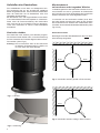
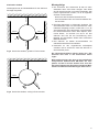
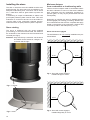
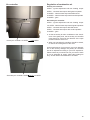
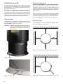
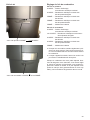
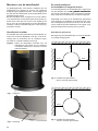
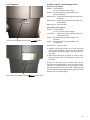
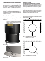
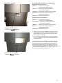
Kaminofen drehbar
Der Kaminofen wird arretiert (nicht drehbar) angelie-
fert. Soll das Gerät drehbar sein, muss die Arretierung
auf der Unterseite der Fußraste abgeschraubt und ent-
fernt werden (siehe Fig.2).
Achtung: Nur bei Anschluss oben ist der Kaminofen
mit Hilfe der Fußraste jeweils in 5 Stufen um
45° nach links und rechts drehbar.
Fig.1 Fußraste
Fig.2 Arretierung
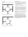
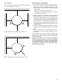
Mindestabstand
zu brennbaren oder tragenden Wänden
Im Strahlungsbereich des Kaminofens dürfen bis zu ei-
nem Abstand von 100 cm, gemessen ab Sichtscheibe
der Feuerraumtür, keine Gegenstände aus brennbaren
Stoffen vorhanden sein oder abgestellt werden.
Je nachdem ob der Kaminofen arretiert (nicht dreh-
bar) oder drehbar montiert wird, gelten je nach Position
der Feuerraumtür zur Aufstell- bzw. Seitenwand unter-
schiedlich einzuhaltende Mindestwandabstände (siehe
Fig.3 bis 6).
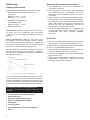
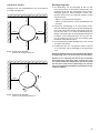
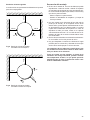
Kaminofen arretiert
Nachfolgend sind die Wandabstände für die nicht dreh-
bare Montage dargestellt.
25 cm
40 cm
40 cm
100 cm
Fig.3 Kaminofen arretiert, gerade in Ecke montiert
25 cm
25 cm
100 cm
Fig.4 Kaminofen arretiert, schräg in Ecke montiert

5
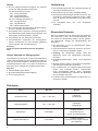
Kaminofen drehbar
Nachfolgend sind die Wandabstände für die drehbare
Montage dargestellt.
25 cm
100 cm
100 cm
100 cm
45°45°
Fig.5 Kaminofen drehbar, gerade in Ecke montiert
40 cm
40 cm
100 cm
45°
45°
Fig.6 Kaminofen drehbar, schräg in Ecke montiert
Montagefolge
● Der Anschluss des Ofenrohres Ø 150 mm kann
wahlweise oben oder hinten erfolgen. Das Gerät
wird für Anschluss oben vormontiert angeliefert. Soll
hinten angeschlossen werden, so ist in folgenden
Schritten umzumontieren:
- Deckel aus der Rückwand herausbrechen.
- Anschlussstutzen oben und Verschlussdeckel hin-
ten tauschen.
● Rohrfutter (bauseitig) in Schornstein einbauen. Die
Anschlusshöhe kann bei Ofenrohranschluss oben
individuell festgelegt werden, sollte aber 1,5 m ab
Anschlussstutzen nicht übersteigen. Anschlusshöhe
bei Ofenrohranschluss hinten siehe Kapitel „Tech-
nische Daten“. Im Umkreis von 20 cm um das
Ofenrohr darf sich bei der Durchführung durch
Bauteile aus brennbaren Stoffen kein brennbares
Material benden.
● Das Ofenrohr an beiden Anschlussstellen mit
Ofenkitt dauerhaft dicht anschließen.
● Kaminofen an den vorgesehenen Aufstellplatz
schieben und so ausrichten, dass das Ofenrohr in
das Rohrfutter passt.
Die Ofenrohranschlüsse müssen dicht sein. Das
Ofenrohr darf nicht in den Schornstein hinein
ragen.
Bitte berücksichtigen Sie, dass an den Stellwänden
entsprechend Prüfvorschrift EN 13240 die Tem-
peratur von 85°C erreicht werden kann und dies
bei hellen Tapeten oder ähnlichen brennbaren Bau-
stoffen zu farblichen Veränderungen führen kann.

6
Bedienung
Zulässige Brennstoffe
Nachfolgend aufgeführte Brennstoffe sind zulässig:
● Naturbelassenes stückiges Holz in Form von
Scheitholz
Maximale Länge: ....33 cm
Umfang: ........... ca. 30 cm
● Holzbrikett nach DIN 51731
Größenklasse HP 2
Maximale Länge: ....20 cm
● Braunkohlenbrikett
Scheitholz erreicht nach Lagerung von 2 bis 3 Jahren
im Freien (nur oben abgedeckt) eine Feuchtigkeit
von 10 bis 15 % und ist dann am Besten zum Heizen
geeignet.
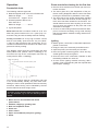
Frisch geschlagenes Holz hat eine sehr hohe
Feuchtigkeit und brennt deshalb schlecht. Neben
dem sehr geringen Heizwert belastet es zusätzlich die
Umwelt. Die erhöhte Kondensat- und Teerbildung kann
zur Kamin- und Schornsteinversottung führen.
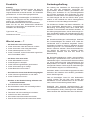
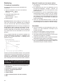
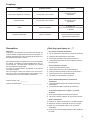
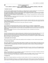
Aus dem Diagramm geht hervor, dass der Verbrauch
bei frisch geschlagenem Holz (Heizwert 2,3 kWh/kg)
im Vergleich zu trockenem Holz (Heizwert 4,3 kWh/kg)
fast doppelt so hoch ist.
Feuchtigkeit [%]
min. 2 Jahre trocken gelagertes Holz
Heizwert [kWh/kg]
frisch geschlagenes Holz
Nur mit trockenen Brennstoffen erreichen Sie eine opti-
male Verbrennung und heizen umweltschonend. Durch
die Brennstoffaufgabe in Teilmengen wird eine unnötige
Emission vermieden. Einen sauberen Abbrand erken-
nen Sie daran, dass sich die Schamotte hell verfärbt.
Laut Bundes-Immissions-Schutzgesetz ist es
verboten, z.B. folgende Brennstoffe in Kaminöfen zu
verfeuern:
● Feuchtes bzw. mit Holzschutzmitteln
behandeltes Holz
● Sägemehl, Späne, Schleifstaub
● Rinden- und Spanplattenabfälle
● Kohlengrus
● sonstige Abfälle
● Papier und Pappe (außer zum Anzünden)
● Stroh
Beachten Sie vor dem ersten Heizen
● Alle Zubehörteile aus dem Aschekasten und
Feuerraum entnehmen.
● Der auftretende Geruch durch das Verdampfen
der Schutzlackierung verschwindet, wenn der
Kaminofen mehrere Stunden gebrannt hat (Raum
gut Lüften).
● Der Kaminofen ist mit einem hochwertigen tempera-
turbeständigen Lack beschichtet, der seine endgülti-
ge Festigkeit erst nach dem ersten Aufheizen erreicht.
Stellen Sie deshalb nichts auf den Kaminofen und
berühren Sie nicht die Oberächen, da sonst die
Lackierung beschädigt werden könnte.
● Bei der Erstinbetriebnahme min. 2 Abbrände mit
ca. 3 kg Brennstoff auegen, damit der tempera-
turbeständige Lack seine endgültige Festigkeit
be kommt.
Anzünden
● Vor dem Anzünden prüfen, dass keine brennbaren
Gegenstände auf dem Kaminofen abgelegt sind.
● Aschekasten ggf. entleeren und wieder einschieben.
● Primär- und Sekundärluftsteller öffnen.
● Anzündmaterial (Anzündwürfel und trockenes, klei-
neres Anzündholz) auegen und anzünden.
● Feuerraumtür schließen, damit das Anzündmaterial
gut anbrennen kann.
● Sobald das Anzündmaterial angebrannt ist, dem
Wärmebedarf entsprechende Menge Brennstoff
nach le gen (siehe Kapitel „Heizen“).

7
Luftsteller
Primärluftsteller: ZU AUF
Sekundärluftsteller: AUF ZU
Einstellen der Verbrennungsluft
Primärluftsteller
AUF ....Anzündstellung und max. Heizleistung
AUF ....Nennheizleistung mit Braunkohlenbrikett
ZU ....... Nennheizleistung mit Scheitholz
ZU ....... Nennheizleistung mit Holzbrikett
ZU ....... Gluthalten
Sekundärluftsteller
AUF ....Anzündstellung und max. Heizleistung
1/5 AUF....Nennheizleistung mit Braunkohlenbrikett
AUF ....Nennheizleistung mit Scheitholz
AUF ....Nennheizleistung mit Holzbrikett
ZU ....... Gluthalten
● Da die Sekundärluft auch maßgeblich zur Schei-
bensauberkeit beiträgt, ist der Sekundärluftsteller
beim Abbrand immer in Richtung auf zu stellen.
● Bei Nichtbetrieb alle Schieber schließen, um ein
Auskühlen des Aufstellraumes zu verhindern.
Da die Leistung Ihres Kaminofens stark vom Schorn-
steinzug abhängt, muss der Primärluftsteller Ihren ei-
genen Erfahrungen entsprechend verstellt werden.
Achten Sie darauf, dass Sie Ihren Kaminofen nicht mit
Luftmangel (Schieberstellung zu klein) betreiben, da so
die Emmisionen ansteigen.

8
Heizen
● Nur die Menge Brennstoff auegen, die entspre-
chend dem Wärmebedarf benötigt wird.
Für Nennheizleistung 5,5 kW:
- max. 1,5 kg Holzscheite
- max. 1,3 kg Holzbrikett
- max. 3 Braunkohlenbrikett
Für max. zulässige Heizleistung:
- max. 3 kg Holzscheite
- max. 3 kg Holzbrikett
- max. 6 Braunkohlenbrikett
● Die Feuerraumtür beim Nachlegen langsam öffnen,
da sonst Heizgase austreten können.
● Aschekasten oder Feuerraum rechtzeitig entleeren.
Sonst Behinderung der Verbrennungsluftzufuhr oder
Schädigung der Rosteinrichtung möglich.
● Aschekasten nur zum Entleeren entnehmen.
● Aschekastenfach regelmäßig bei herausgenom-
menem Aschekasten von evtl. daneben gefallener
Asche reinigen (z.B. mit Staubsauger).
Achtung:
Gerät und Ascherückstände müssen abgekühlt
sein.
Heizen während der Übergangszeit
Voraussetzung für eine gute Funktion des Kaminofens
ist der richtige Förderdruck (Schornsteinzug). Dieser ist
sehr von der Außentemperatur abhängig. Bei höheren
Außentemperaturen (über 16°C) kann es deshalb zu
Störungen durch mangelnden Förderdruck kommen.
Was tun?
● Primärluftsteller ganz öffnen.
● Nur kleine Menge Brennstoff auegen.
● Asche häug schüren.
Verkleidung
● Die Verkleidungen dürfen nicht überheizt werden, da
sonst Risse auftreten können.
● Mit maximal 3 kg Holz oder Holzbrikett heizen.
● Die Natursteinverkleidungen werden aus einem „ge-
wachsenem“ Steinblock hergestellt werden, daher
kann die Struktur und Farbgebung sehr unterschied-
lich sein.
● Die Oberäche kann sich unter Temperatur
ver ändern.
Besondere Hinweise
Bei einer wesentlichen oder dauernden Überbelastung
das Kaminofens über die Nennwärmeleistung hin-
aus sowie bei Verwendung anderer als der genann-
ten Brennstoffe, entfällt die Gewährleistung des
Herstellers.
● Der Kaminofen ist nur mit geschlossener Feuer-
raumtür zu betreiben.
● Keine heiße Asche entnehmen. Asche nur in feuersi-
cheren, unbrennbaren Behältern lagern.
● Achtung: Die Oberächen werden heiß! Zur
Bedienung immer den beiliegenden Handschuh
benutzen.
● Konvektionsluftöffnungen dürfen nicht abgedeckt
werden.
● Niemals Spiritus, Benzin oder andere feuergefährli-
che Stoffe zum Anzünden verwenden.
● Die Vorkehrungen zur Verbrennungsluftversorgung
dürfen nicht verändert werden. Insbesondere
muss sichergestellt bleiben, dass notwendige
Verbrennungsluftleitungen während des Betriebes
der Feuerstätte offen sind.
● Es dürfen keine Veränderungen am Kaminofen vor-
genommen werden.
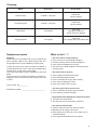
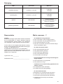
Reinigung
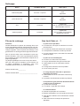
Was? Wie oft? Womit?
Kaminofen innen min. 1 x pro Jahr
Handfeger,
Staubsauger
Verbindungsstück min. 1 x pro Jahr
Handfeger,
Staubsauger
Glasscheibe nach Bedarf
in kaltem Zustand
mit Glasreiniger für
Kamin- und Ofenscheiben
lackierte Oberächen nach Bedarf
in kaltem Zustand
mit einem leicht angefeuchteten
Micro faser tuch

9
Ersatzteile
Achtung:
Eventuell benötigte Ersatzteile fordern Sie bitte bei
Ihrem Fachhändler an. Es dürfen ausschließlich
Original-Ersatzteile verwendet werden. Für Ersatzteile
garantieren wir 10 Jahre Ver sor gungs sicherheit.
Um Ihren Auftrag schnellstmöglich zu bearbeiten, be-
nötigen wir unbedingt die auf dem Geräteschild ange-
gebene Typ- und Fabrikationsnummer.
Das Geräteschild bendet sich auf der Rückwand.
Damit Sie die auf dem Geräteschild bendlichen
Nummern zur Hand haben, wird empfohlen, sie vor der
Installation hier einzutragen:
Typnummer: 28/__________
Fabrikationsnummer: _________________________
Was ist, wenn …?
... der Kaminofen nicht richtig zieht?
● Ist der Schornstein oder das Ofenrohr undicht?
● Ist der Schornstein nicht richtig bemessen?
● Ist die Außentemperatur zu hoch?
● Ist die Tür anderer, an den Schornstein angeschlos-
sener Feuerstätten offen?
... der Raum nicht warm wird?
● Ist der Wärmebedarf zu hoch?
● Ist das Abgasrohr verstopft?
● Ist die Verbrennungsluftzufuhr geschlossen?
● Ist der Schornsteinzug zu niedrig?
● Ist das Brennholz nicht trocken?
... der Kaminofen eine zu hohe Heizleistung abgibt?
● Ist die Verbrennungsluftzufuhr zu weit offen?
● Ist der Förderdruck zu hoch?
... Schäden an der Rosteinrichtung auftreten oder
sich Schlacke bildet?
● Der Kaminofen wurde überlastet.
● Der Aschekasten wurde nicht rechtzeitig entleert.
… der Schornstein brennt?
● Feuerwehr und Schornsteinfeger informieren.
● Luftzufuhr am Ofen minimieren.
● Schornstein kontrolliert ausbrennen lassen.
● Ursache durch Fachpersonal untersuchen lassen.
Sachmängelhaftung
Die Haftung des Verkäufers für Sachmängel rich-
tet sich nach den gesetzlichen Vorschriften der
§§ 437 ff BGB. Danach besteht grundsätzlich eine
Haftung des Verkäufers für die Sachmängelfreiheit
des Produkts gegenüber dem Endkunden für einen
Zeitraum von zwei Jahren. Im Falle des Vorliegens ei-
nes Sachmangels hat sich der Käufer daher grund-
sätzlich an den Verkäufer als seinen Vertragspartner
zu wenden und dort den Mangel anzumelden.
Für Schäden an Geräten oder deren Anbauteilen, die
durch übermäßige Beanspruchung, unsachgemäße
Behandlung und Wartung sowie durch Fehler beim
Aufstellen und Anschließen des Gerätes auftreten, ist
die Haftung ausgeschlossen, da kein Sachmangel vor-
liegt. Unerlaubte Eingriffe und Veränderungen an dem
Gerät können zum Erlöschen der Sachmängelhaftung
führen.
Bei Keramikverkleidungen beeinträchtigen Haarrisse
die Funktionsfähigkeit der Keramik nicht. Jedes Ke-
ramikbauteil wird in Handarbeit hergestellt. Farbun-
terschiede bei Glasuren sowohl in Helligkeit als auch
Farbtönung können von Keramikbrand zu Keramik-
brand in Nuancen auftreten. Diese Unterschiede kön-
nen deutlich bei Lieferung von einzelnen Ersatz-
teilkeramiken auftreten und sind kein Grund zur
Beanstandung.
Bei Natursteinverkleidungen stellen unterschiedliche
Maserungen, quarzähnliche Linien, Farbnuancen und
Farbabweichungen, unterschiedliche Steineinschlüsse
o.ä. keinen Sachmangel dar. Steinverkleidungen sind
Naturprodukte, bei welchen derartige Abweichungen
naturgemäß auftreten. Gleiches gilt für Veränderungen
der Oberäche aufgrund von Hitzeeinwirkung.
Außerdem stellen auch Ausdehnungsgeräusche beim
Aufheizen oder Abkühlen des Gerätes grundsätzlich
keinen Sachmangel dar.
Falls ein berechtigter Grund für eine Reklamation
vorliegt, wenden Sie sich bitte unter Angabe des
Kaufdatums und der Gerätenummer an den Fachbe-
trieb, bei dem Sie das Gerät gekauft haben.
Ersatzteile oder eventuell auszutauschende Ver-
schleißteile wie feuerberührte Teile (Vermiculiteplatten,
Schamotteplatten, Roste), Dichtungen oder Glas ke ra-
miken be ziehen Sie ebenfalls über Ihren Fachbetrieb.

10
Foreword
This stove is a top quality modern heating technology
product.
A large degree of user comfort and high fuel utilisa-
tion enable it to be used as high quality space heat-
ing, without having to do without the cosy atmosphere
of an open re.
Proper installation and correct handling and care are
indispensable for problem-free operation and a long
service life. Please therefore observe all the informa-
tion given in these instructions. We are convinced that
you will then derive a great deal of pleasure from this
stove. Please keep these instructions in a safe place
so that you can read through them at the start of each
heating period.
Should you nd any transport damage, please report it
to your supplier immediately as otherwise it will not be
possible to correct the damage free of charge.
Stove Virgo 28/865
Table of Contents
Foreword ................................................................. 10
Technical Data ........................................................ 11
Regulations to be observed .................................. 11
Chimney design ...................................................... 11
Combustion air supply ........................................... 11
External combustion air connection...........................11
Installing the stove ................................................. 12
Stove rotating ........................................................... 12
Minimum distance
from combustible or load-bearing walls .................... 12
Assembly sequence ................................................. 13
Operation ................................................................. 14
Permissible fuels ...................................................... 14
Please note before heating for the rst time ............. 14
Igniting ...................................................................... 14
Air controller ............................................................. 15
Regulation of combustion air .................................... 15
Heating ..................................................................... 16
Heating during the transition period.......................... 16
Cladding .................................................................. 16
Special information ................................................ 16
Cleaning .................................................................. 17
Replacement parts ................................................. 17
What to do if ...? ...................................................... 17

11
Technical Data
● Nominal thermal output ................................. 5,5 kW
● Height to middle of the connector pipe
with the connection at the back 1) ............... 933 mm
● Height to the top edge of connector pipe
with the connection at the top .....................1128 mm
● Connection pipe ...................................... Ø 150 mm
● max. Weight................................................... 155 kg
● Height to middle
of combustion air connection ....................... 180 mm
● Connection combustion air ...................... Ø 125 mm
● Operating mode ........................ Intermitting burning
1)
If the rear connection is used, the appliance can no
longer rotate.
Regulations to be observed
● Local and building law regulations
● The stove must be installed by a professional and
connected to the chimney. The specic national reg-
ulations for safe installation of the connector must be
complied with. The connecting piece used must pos-
sess an opening for cleaning.
● The stove must be regularly checked by a
professional.
The heating stove’s re door is self-closing; it is there-
fore approved for connection to chimneys with multiple
connections.
Chimney design
The chimney design is according to DIN EN 13384 - 2
or to the specic national regulations. The chimney
must comply with the temperature class T400.
Necessary data
Closed operation:
● Nominal thermal output ................................. 5,5 kW
● Waste air mass ow rate ............................... 5,3 g/s
● Waste air temperature ................................... 277 °C
● Minimum delivery pressure at
nominal thermal output .................................... 12 Pa
Combustion air supply
It must be guaranteed that there is enough combustion
air available for the stove. For the proper function of the
stove, a necessary combustion air volume current of
15,6 m³/h must be considered.
External combustion air connection
By an external operating mode, the combustion air
can be added from outside through a leak-proof line or
through a supply duct in the chimney. Thus, speak with
your district chimney sweep master.
Due to energy saving reasons, the combustion air in-
let should be able to be blocked if the stove is not being
operated. This can occur through a shut-off valve in the
combustion air line or through the air slide valves on
the stove. If a shut-off valve is used, this must be clear-
ly identied with CLOSED/OPEN.
Through the shutoff, it is avoided that heat is removed
from the set-up room through the constant circulation
of cold combustion air and cold combustion air lines
may lead to an increased formation of condensation.
Attention:
The combustion air line may not be closed during
operation!
In order to feed the combustion air to the stove exter-
nally via a pipe instead of from the room in which it is
installed, it is possible to screw a Ø 125 mm combus-
tion air pipe to the back of the stove. If the combus-
tion air pipe installed is longer than 3 m, calculations
will have to be carried out to verify an adequate sup-
ply of combustion air. At extremely low outdoor temper-
atures, condensation can occur on the combustion air
duct. For this reason it must be insulated with a suitable
insulating material. Observe the rules of the oven and
air heating construction craft.
Use the Olsberg combustion air pipes with sealing lip.
Attention:
Appliances with external combustion air connec-
tion are not suitable for concurrent operation with
ventilation systems, without a supplemental safe-
ty system.

12
Installing the stove
The oor on which the stove is installed must be even
and horizontal. The stove may only be installed on an
adequate load-bearing oor. The stove can be stood
on a metal oor sheet or glass sheet to protect the
ooring.
If the ooring or carpet is inammable, a stable, heat
proof spark protection plate must be used. This must
extend 50 cm to the front and 30 cm to each side be-
yond the edge of the combustion chamber opening.
Under the stove no spark protection plate is required.
Stove rotating
The stove is delivered with the arrest engaged
(non-rotating). If the stove should rotate, the arrest on
the underside of the footrest must be unscrewed and
removed (see Fig.2).
Attention: Only with the top connection can the stove
be rotated via the footrest in 5 stages, 45°
to the left and the right.
Fig.1 Footrest
Fig.2 Arrest
Minimum distance
from combustible or load-bearing walls
There must be no objects made of combustible materi-
als within a distance of 100 cm of the stove’s radiation
area, measured from the combustion chamber’s in-
spection glass, nor may any be placed within this area
subsequently.
Depending on whether the stove is installed with the
arrest engaged (non-rotating) or rotating, different min-
imum wall distances that must be complied with apply,
based on the position of the combustion chamber door
to the set-up wall or side wall (see Fig. 3 to 6).
Stove with arrest engaged
The wall distances for non-rotating installation are pre-
sented below.
25 cm
40 cm
40 cm
100 cm
Fig.3 Stove with arrest engaged,
installed straight in corner
25 cm
25 cm
100 cm
Fig.4 Stove with arrest engaged,
installed diagonally in corner

13
Stove rotating
The wall distances for rotating installation are present-
ed below.
25 cm
100 cm
100 cm
100 cm
45°45°
Fig.5 Stove rotating, installed straight in corner
40 cm
40 cm
100 cm
45°
45°
Fig.6 Stove rotating, installed diagonally in corner
Assembly sequence
● The Ø 150 stovepipe connection can be installed at
the top or rear. The stove is supplied ready for con-
nection from above. If you wish to connect it at the
rear, the following steps must be carried out to make
the necessary modications:
- Break out the cover in the back panel.
- Replace the connector sleeve and the sealing
cover.
● Install the pipe lining (provided on site) in the chim-
ney. The connection height can be individually spec-
ied for a top stovepipe connection, however should
not exceed 1.5 m from the connector sleeve. For the
rear stovepipe connection heights please refer the
“Technical Data“ chapter. No combustible material is
permitted within a radius of 20 cm around the stove
pipe.
● Connect the stovepipe at both connection points
with stove putty so that the stove pipe is permanent-
ly sealed.
● Push the stove onto its planned position and orient it
so that the stovepipe ts into the pipe lining.
The stovepipe connections must be tight. The
stovepipe must not protrude into the chimney.
Bear in mind that on partition walls in accordance
with test specication EN 13240 the temperature
of 85°C can be reached, and with light wallpaper
or similar combustible construction materials this
can result in colour changes.

14
Operation
Permissible fuels
The following fuels are approved:
● Natural shopped wood in the form of billet wood
Maximum length: ..............33 cm
Circumference: ....approx. 30 cm
● Wood briquettes to DIN 51731
Size class HP 2
Maximum length: ..............20 cm
● Lignite briquettes
Billet wood reaches a moisture content of 10 to 15%
after being stored outdoors for 2 to 3 years (only cov-
ered at the top) and is then ideally suited for heating.
Freshly cut wood has a very high moisture content
and so burns badly. Apart from the very low calorif-
ic value it is also harmful for the environment. The in-
creased condensate and tar formation can lead to re-
place and chimney sooting.
This diagram shows that the consumption rate with
freshly-felled wood (caloric value 2.3 kWh/kg) is al-
most twice as high as the consumption rate with dry
wood (caloric value 4.3 kWh/kg).
Moisture [%]
dry wood that has been stored for at least 2 years
Caloric value [kWh/kg]
freshly-felled wood
You will only achieve optimum combustion and heat
in an environmentally friendly way with these fuels.
Adding the fuel in small quantities avoids unnecessary
emissions. Clean burning can be identied by the fact
that the rebrick becomes a light colour.
According to the German Federal Immission Control
Act, it is forbidden e.g. to burn the following fuels in
stoves:
● Moist wood or wood treated with wood
preservatives
● Sawdust, chippings, grinding dust
● Bark and chipboard waste
● Slack coal
● Other wastes
● Paper and cardboard (except for igniting)
● Straw
Please note before heating for the rst time
● Remove all accessories from the ash pan and com-
bustion chamber.
● The odour given off by the evaporation of the pro-
tective coating disappears after the stove has been
burning for several hours (ventilate the room well).
● The stove has a high quality temperature resistant
coat, which does not achieve its nal strength un-
til the stove has been heated for the rst time. You
should therefore never leave anything on the stove
and not touch the surfaces as the paint coat could
otherwise be damaged.
● As soon as the kindling material has burned down,
put on 2 burnouts consisting of 3 kg wood ensuring
that the temperature resistant coating reaches its -
nal rmness.
Igniting
● Before ignition, check that no ammable objects are
placed on the stove.
● Empty the ash pan if necessary and slide back in.
● Open the primary and secondary air controller.
● Place the ignition material (ignition cubes and dry,
smaller ignition wood) and ignite it.
● Close the door to the combustion chamber so that
the kindling material can catch re.
● As soon as the igniting material is burning, add a
quantity of fuel corresponding with the required heat
(see chapter “heating”).

15
Air controller
Primary air controller: CLOSED OPEN
Secondary air controller: OPEN CLOSED
Regulation of combustion air
Primary air controller
OPEN ....Ignition adjustment and max. heating output
OPEN ....Nominal heat output with lignite briquettes
CLOSED ....Nominal heat output with billet wood
CLOSED ....Nominal heat output with wood briquettes
CLOSED ....glow
Secondary air controller
OPEN ....Ignition adjustment and max. heating output
1/5 OPEN ..Nominal heat output with lignite briquettes
OPEN ....Nominal heat output with billet wood
OPEN ....Nominal heat output with wood briquettes
CLOSED ....glow
● As the secondary air also contributes to the cleanli-
ness of the glass pane, the secondary air controller
must always be moved in the direction of the open
position while the stove is lit.
● When not operating all controllers should be closed,
to reduce the cooling down of the room.
As the performance of your stove is very much depend-
ent on the chimney draught, the primary air controller
has to be adjusted according to your own experience.
Please note that you should not use your stove if there
is not an adequate air supply (slide valve setting too
low), as this causes the emissions to increase.

16
Heating
● Only place the quantity of fuel required to achieve
the heating requirement.
For a nominal heating output 5,5 kW:
- max. 1,5 kg billet wood
- max. 1,3 kg wood briquettes
- max. 3 lignite briquettes
For max. heat output allowed:
- max. 3 kg billet wood
- max. 3 kg wood briquettes
- max. 6 lignite briquettes
● Open the combustion chamber door slowly for add-
ing new fuel, as otherwise the combustion gases can
escape.
● Empty the ash pan or combustion chamber in good
time. Otherwise it is possible for the combustion air
intake to be blocked or for the grate to be damaged.
● Only remove the ash pan to empty it.
● Clean the ash pan compartment regularly after re-
moving the ash pan to remove any ash that may
have been spilled (e.g. use a vacuum cleaner).
Attention:
Any stove and ash residues must have been left to
cool before being removed.
Heating during the transition period
Prerequisite for the stove to function well is the correct
delivery pressure (chimney draught). This very much
depends on the external temperature. Therefore, if the
external temperatures are high (above 16°C) the deliv-
ery pressure can be disrupted.
What to do?
● Open the primary air controller complete.
● Only put on a small quantity of fuel.
● Frequently stoke the ash.
Cladding
● The cladding may not be overheated, as cracks
could appear.
● Use a maximum of 3 kg wood or briquette for heating.
● As the natural cladding comes from a „grown“ boul-
der, structure and colour scheme may be very
different.
● The surface may be altered under temperature
inuence.
Special information
The manufacturer’s guarantee expires if the stove is
signicantly or permanently overloaded above the
nominal heating output, or if fuels other than those list-
ed are used.
● The stove must only be used with the combustion
chamber door shut.
● Never remove hot ashes. Only store ashes in a re-
proof, non-combustible container.
● Attention: The surfaces get hot! Always use the en-
closed glove when operating the stove.
● Convection air openings may not be covered.
● Never use white spirit, benzene or other inamma-
ble, hazardous materials to ignite the re.
● The combustion air supply ttings must never be al-
tered. In particular, it must be ensured that any nec-
essary combustion air pies are open while the re-
place is being used.
● Do not make any changes or modications to the
stove.

17
Cleaning
What? How often? Using what?
inside of stove at least 1 x per year
hand brush,
vacuum cleaner
connection piece at least 1 x per year
hand brush,
vacuum cleaner
glass panel as required
when cold
using glass cleaner for
stoves- and oven glasses
painted surfaces as required
when cold
with a slightly damp microbre cloth
Replacement parts
Attention:
Please ask your specialist trader for any replacement
parts required. Always use original spare parts only.
We guarantee a ten-year availability of spare parts.
In order to process your order as quickly as possible, it
is imperative that you send us the type and fabrication
number given on the stove’s rating plate.
The stove identication plate is situated on the back
panel.
We recommend the relevant numbers here before in-
stalling the stove to ensure that you always have them
to hand:
Type number: 28/__________
Fabrication number: __________________________
What to do if ...?
... the stove doesn’t draw properly?
● Is the chimney or the stovepipe not tight?
● Has the chimney been incorrectly designed?
● Is the external temperature too high?
● Are the doors of other replaces connected to the
chimney open?
... the room doesn’t get hot?
● Is the heating requirement too high?
● Is the waste gas pipe blocked?
● Is the combustion air supply been closed?
● Is the chimney draught too low?
● Is the wood used as fuel not dry?
... the stove gives off too much heat?
● Is the combustion air supply open too wide?
● Is the delivery pressure too high?
... the grate becomes damaged or slags are formed?
● The stove was overloaded.
● The ash pan was not emptied in good time.
... the chimney catches re?
● Inform the re services and chimney sweep.
● Minimize the air supply to the stove.
● Allow the re in the chimney to burn itself out in a
controlled fashion.
● Have a professional determine the cause?

18
Préface
Ce poêle est un produit de pointe de la technique de
chauffage moderne.
Un grand confort de manipulation et une mise à prot
élevée du combustible permettent d’employer ce four
comme chauffage intérieur de qualité sans devoir re-
noncer à l’atmosphère douillet d’un feu de cheminée.
L’installation en bonne et due forme ainsi que le ma-
niement et l’entretien correct du poêle sont indispen-
sables pour assurer le parfait fonctionnement et une
longue durée de vie. C’est pourquoi il convient de res-
pecter toutes les indications de ce mode d’emploi.
Nous sommes convaincus que vous aurez beaucoup
de plaisir à l’emploi de ce poêle. Conservez bien ce
mode d’emploi an de trouver les informations néces-
saires sur la manipulation correcte à chaque début de
période de chauffage.
Si vous constatez une détérioration due au transport,
veuillez en informer immédiatement votre fournisseur,
car sinon vous ne pourrez pas jouir du règlement gra-
tuit du dommage.
Poêle Virgo 28/865
Table des matières
Préface..................................................................... 18
Caractéristiques technique ................................... 19
Directives à respecter ............................................ 19
Dimensions de la cheminée .................................. 19
Alimentation en air de combustion ....................... 19
Raccord d’air de combustion externe ....................... 19
Installation du poêle ............................................... 20
Poêle pivotant ........................................................... 20
Distance minimum de
parois inammables ou de murs porteurs ................ 20
Déroulement du montage ......................................... 21
Manipulation ........................................................... 22
Combustibles autorisés ............................................ 22
À respecter avant la première mise en service
chauffer ..................................................................... 22
Allumage................................................................... 22
Vérin à air ................................................................. 23
Réglage de l‘air de combustion ................................ 23
Chauffer .................................................................... 24
Chauffer durant la période de transition ................... 24
Habillage.................................................................. 24
Indications spéciales ............................................. 24
Nettoyage ................................................................ 25
Pièces de rechange ................................................ 25
Que faut-il faire si …? ............................................ 25

19
Caractéristiques technique
● Rendement thermique nominal ..................... 5,5 kW
● Hauteur jusqu’au milieu
du manchon de raccord
pour raccord arrière 1) ................................. 933 mm
● Hauteur jusqu’au bord supérieur
du manchon de raccord
pour raccord en haut ..................................1128 mm
● Manchon de raccord ................................ Ø 150 mm
● max. Poids ..................................................... 155 kg
● Hauteur jusqu’au milieu
du manchon de raccord air de combustion
... 180 mm
● Manchon de raccord air de combustion
.... Ø 125 mm
● Type de service .................. Combustion temporisée
1)
En cas de raccordement par l‘arrière, il ne sera plus
possible de tourner le poêle.
Directives à respecter
● Prescriptions locales et relatives à la législation sur
les constructions
● Un spécialiste devra installer la poêle et raccorder
à la cheminée. Les prescriptions nationales doivent
être respectées pour garantir une installation sûre
de la pièce de raccordement. Le raccord utilisé doit
est muni d‘une ouverture de nettoyage.
● Un contrôle régulier du poêle doit être exécuté par
un spécialiste.
Le poêle est muni d’une porte de foyer à fermeture au-
tomatique. Son raccord sur des cheminées à occupa-
tion multiple est donc autorisé.
Dimensions de la cheminée
Les dimensions de la cheminée répondent à la norme
EN 13384 - 2 selon les prescriptions nationales. La
cheminée doit se conformer à la classe de tempéra-
ture T400.
Données nécessaires
Exploitation fermée:
● Rendement thermique nominal ..................... 5,5 kW
● Débit massique de gaz d’évacuation ............. 5,3 g/s
● Température de gaz d’évacuation ................. 277 °C
● Pression de refoulement minimale pour
un rendement thermique nominal ....................12 Pa
Alimentation en air de combustion
Il faut veiller à ce que le poêle dispose de sufsamment
d’air de combustion. Pour un fonctionnement impec-
cable du poêle, un débit volumique d’air de combustion
de 15,6 m³/h doit être pris en compte.
Raccord d’air de combustion externe
Pour un fonctionnement externe, l’air de combustion
peut être apporté depuis l’extérieur par une conduite
étanche ou par une buse dans la cheminée. Vous de-
vez donc en parler avec votre spécialiste en chemi-
nées et ramonage.
Pour des raisons d’économies d’énergie, lorsque le
poêle n’est pas utilisé, l’arrivée d’air de combustion de-
vra être fermée. Ceci peut être réalisé avec un clapet
de fermeture dans la conduite d’air de combustion ou
avec du levier de commande pour l’alimentation en air
de combustion. En cas d’utilisation d’un clapet de fer-
meture, celui-ci doit présenter les marques OUVERT/
FERME de manière bien visible.
En fermant l’arrivée d’air, on empêchera une déperdi-
tion de chaleur dans la pièce en raison de la circula-
tion continue d’air froid de combustion et une forma-
tion de condensation accrue sur les conduites froides
de combustion.
Attention:
La conduite d’air de combustion ne peut pas être
obstruée pendant le fonctionnement!
An de pouvoir amener l‘air de combustion à l‘appareil
non de la pièce où il se trouve mais de l‘extérieur par
l‘intermédiaire d‘un conduit, il est possible de visser sur
la partie arrière de l‘appareil un raccord à air de com-
bustion de Ø 125 mm. Si le conduit d‘air à combustion
est plus long que 3 m, il faut fournir le calcul justicatif
pour l‘alimentation en air de combustion. Dans le cas
de très basses températures extérieures, de la conden-
sation peut se former sur le conduit d‘air de combus-
tion. Il convient donc de l‘isoler avec un matériau iso-
lant approprié. Veuillez respecter les règles du fabri-
cant de système de chauffage à air pulsé et de poêles.
Utilisez les tubes d’air de combustion Olsberg avec
lèvre d’étanchéité.
Attention:
Les poêles dotés d‘un raccordement à l‘air de
combustion extérieur ne conviennent pas pour
être utilisés en même temps avec des installa-
tions de ventilation sans équipement de sécurité
supplémentaire.

20
Installation du poêle
Le sol doit être plan et horizontal. Le poêle ne peut être
posé que sur un sol sufsamment robuste. Pour proté-
ger le plancher, on pourra placer le poêle sur une tôle
ou une plaque de verre.
En présence de moquettes ou de tapis combustibles, il
faut utiliser une spark plaque de protection robuste et
résistante à la chaleur. Ce support de protection doit
dépasser de 50 cm vers l‘avant et de 30 cm sur les cô-
tés à partir de l‘ouverture du foyer du poêle. Sous le
poêle sans spark plaque de protection est requis.
Poêle pivotant
Le poêle est fourni bloqué, c‘est-à dire non pivotant. Si
le poêle doit pouvoir pivoter, il faut dévisser le blocage
sous la pédale et l‘enlever (voir Fig.2).
Attention: À l‘aide de la pédale, le poêle peut être tour-
né de 45° vers la gauche ou vers la droite
en 5 étapes, mais seulement s‘il est raccor-
dé par le haut.
Fig.1 Pédale
Fig.2 Blocage
Distance minimum de
parois inammables ou de murs porteurs
Aucun objet confectionné à partir de matériaux com-
bustibles ne doit se trouver ou être installé dans la
zone de rayonnement du poêle, donc à une distance
inférieure à 100 cm, mesurée à partir de la vitre de la
porte du foyer.
Suivant que le poêle est installé de manière station-
naire ou pivotante, il convient de respecter différents
écartements minimum au mur entre la porte du foyer et
le mur d’installation ou le mur de côté (voir Fig.3 à 6).
Poêle stationnaire
Les écartements au mur représentés ci-après valent
pour une installation stationnaire.
25 cm
40 cm
40 cm
100 cm
Fig.3 Poêle stationnaire, installé droit dans le coin
25 cm
25 cm
100 cm
Fig.4 Poêle stationnaire, installé en biais dans le coin
Seite wird geladen ...
Seite wird geladen ...
Seite wird geladen ...
Seite wird geladen ...
Seite wird geladen ...
Seite wird geladen ...
Seite wird geladen ...
Seite wird geladen ...
Seite wird geladen ...
Seite wird geladen ...
Seite wird geladen ...
Seite wird geladen ...
Seite wird geladen ...
Seite wird geladen ...
Seite wird geladen ...
Seite wird geladen ...
Seite wird geladen ...
Seite wird geladen ...
Seite wird geladen ...
Seite wird geladen ...
Seite wird geladen ...
Seite wird geladen ...
Seite wird geladen ...
Seite wird geladen ...
-
 1
1
-
 2
2
-
 3
3
-
 4
4
-
 5
5
-
 6
6
-
 7
7
-
 8
8
-
 9
9
-
 10
10
-
 11
11
-
 12
12
-
 13
13
-
 14
14
-
 15
15
-
 16
16
-
 17
17
-
 18
18
-
 19
19
-
 20
20
-
 21
21
-
 22
22
-
 23
23
-
 24
24
-
 25
25
-
 26
26
-
 27
27
-
 28
28
-
 29
29
-
 30
30
-
 31
31
-
 32
32
-
 33
33
-
 34
34
-
 35
35
-
 36
36
-
 37
37
-
 38
38
-
 39
39
-
 40
40
-
 41
41
-
 42
42
-
 43
43
-
 44
44


Konigshutte Virgo 28/865 Benutzerhandbuch
- Kategorie
- Öfen
- Typ
- Benutzerhandbuch
in anderen Sprachen
- English: Konigshutte Virgo 28/865 User manual
- français: Konigshutte Virgo 28/865 Manuel utilisateur
- español: Konigshutte Virgo 28/865 Manual de usuario
- Nederlands: Konigshutte Virgo 28/865 Handleiding
Andere Dokumente
-
Olsberg Minerva plus Bedienungsanleitung
-
HASE OTTAWA Bedienungsanleitung
-
-
-
-
-
-
-
Austro Flamm PallaS Bedienungsanleitung
-
 THORMA FALUN Bedienungsanleitung
